Week 14
Interface and Application Programming
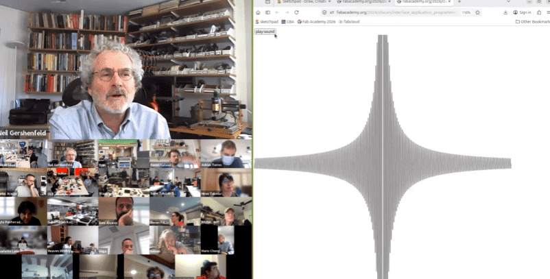
Class with Neil
During this week’s class, Neil introduced the fundamentals of Interface and Application Programming, focusing on how software applications can communicate with embedded systems in real time. The session explored different programming tools, development environments, and communication methods used to create interfaces between users and electronic devices. We also learned how applications can process input and output data from sensors, displays, buttons, and other peripherals connected to microcontroller boards.
Another important topic discussed during the class was the comparison between multiple interface development tools and programming approaches, analyzing their advantages depending on the project requirements. The class emphasized the importance of serial communication, graphical user interfaces, and real-time interaction between hardware and software. These concepts helped me better understand how to create applications capable of controlling and monitoring embedded systems efficiently.
Have you answered these questions?
- I. Linked to the group assignment page. ✅
- II.Documented your project and what you have learned from implementing networking and/or communication protocols. ✅
- III.Explained the programming process(es) you used.. ✅
- IV. Ensured and documented that your addressing for boards works✅
- V. Outlined problems and how you fixed them. ✅
- VI.Included design files (or linked to where they are located if you are using a board you have designed and fabricated earlier) and original source code.✅
- VII.Included a ‘hero shot’ of your network and/or communications setup✅
Hero Shot
For this section, I created a visual composition using a photograph taken at the Faculty of Architecture of the National University of Engineering. In the image, I appear interacting with a scaled version of the Lanzón Monolith, which helps to give a better sense of proportion and presence of the piece in a real environment. This approach allowed me to connect my digital fabrication work with a physical and contextual setting.
To enhance the visual impact, I edited the image in Photoshop, integrating the 3D model into the scene in a realistic way. I adjusted lighting, perspective, and shadows so that the piece blends naturally with the environment. This final composition not only presents the project in a more engaging way but also reinforces the concept and cultural inspiration behind the design.
Group Assignment:
°Compare as many tool options as possible.
° Document your work on the group work page and reflect on your individual page what you learned.
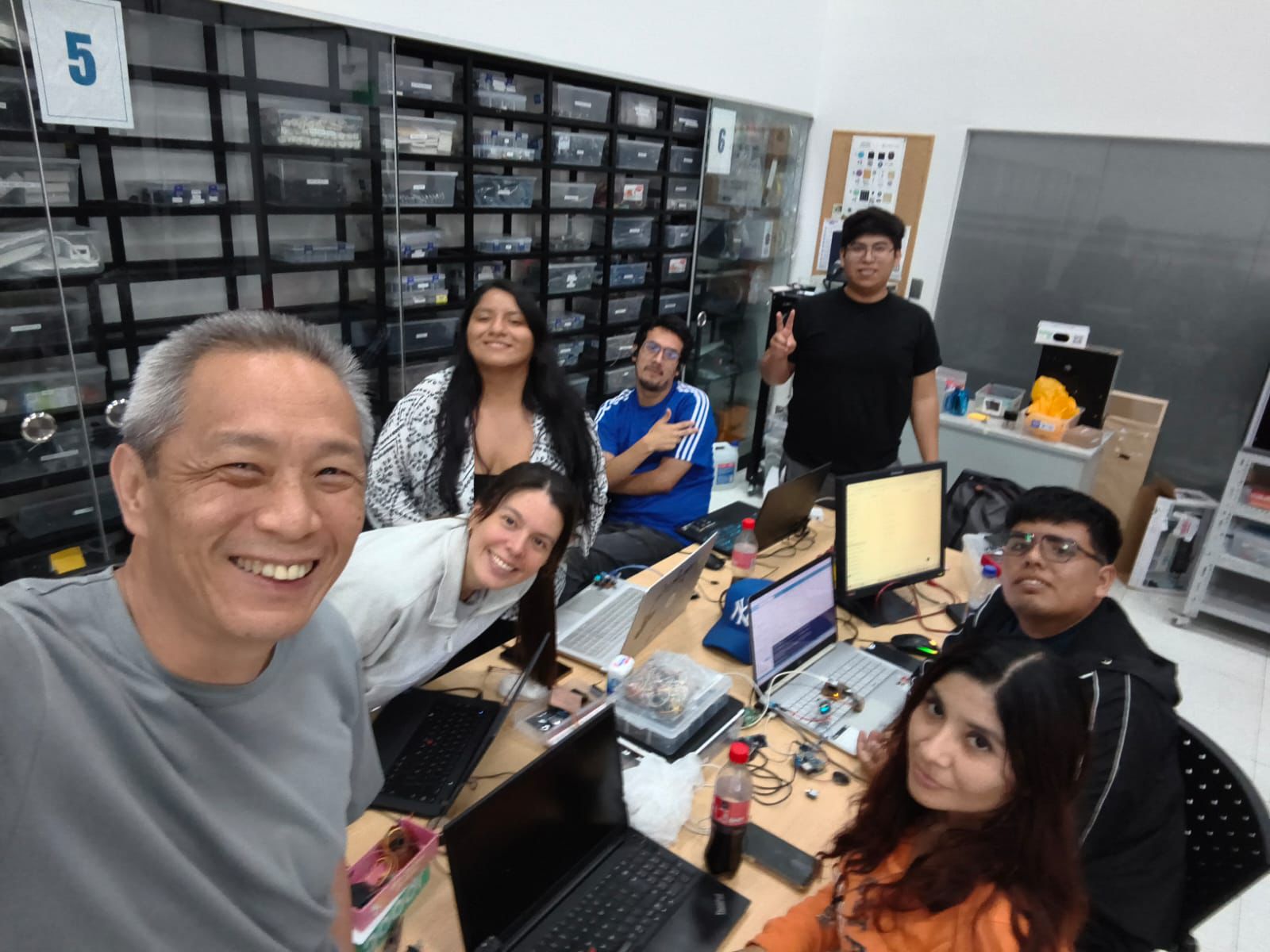
Group Assignment Sumary
During the group assignment, our team explored different software tools for interface and application programming used in embedded systems. We divided the work into subgroups to compare multiple platforms such as AppInventor, Processing, and RemoteXY. Each subgroup tested the capabilities, communication methods, and ease of use of their assigned software while working with different microcontroller boards. This activity allowed us to understand the advantages and limitations of each platform when developing interfaces for digital fabrication projects.
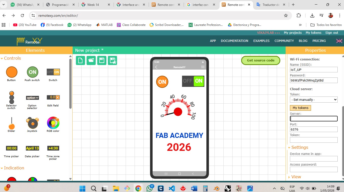
In my subgroup, we worked with RemoteXY to create a simple mobile interface capable of communicating with an embedded board. We tested the connection between the application and the microcontroller using wireless communication and verified that the interface could send and receive data successfully. Through this process, we learned how interface applications can simplify user interaction with electronic systems and how rapid prototyping tools like RemoteXY can accelerate the development of functional embedded applications..
Here is the link to learn more about the group project.
Group Reflection
Through this group assignment, I learned that there are many different tools available for interface and application programming, and each one offers unique advantages depending on the project requirements. Comparing platforms such as AppInventor, Processing, and RemoteXY helped me better understand how interfaces can communicate with embedded systems using different methods such as WiFi, Bluetooth, or serial communication. I also learned the importance of selecting the right tool based on the complexity, flexibility, and development speed needed for a project.
Working with RemoteXY allowed me to gain practical experience in creating a simple and functional user interface for an embedded board. I learned how to establish communication between a mobile application and a microcontroller , as well as how to control outputs and monitor system behavior in real time. This assignment improved my understanding of interface programming and showed me how software and hardware can work together to create interactive digital fabrication projects.
Individual Reflection (Group Work)🧠
During the group work, I contributed by participating in the testing and development of a simple interface using RemoteXY. I collaborated with my subgroup to explore how the platform communicates with embedded boards and how user controls can interact with electronic devices in real time. This experience helped me better understand the workflow involved in interface design, communication setup, and application testing for embedded systems.
From this activity, I learned that interface programming is an important part of creating interactive digital fabrication projects. I also understood that different software tools provide different levels of flexibility and complexity depending on the application. Working with RemoteXY showed me how quickly a functional interface can be developed, while also helping me improve my problem-solving skills during the communication and testing process.
Individual Assignment:
° From this activity, I learned that interface programming is an important part of creating interactive digital fabrication projects. I also understood that different software tools provide different levels of flexibility and complexity depending on the application. Working with RemoteXY showed me how quickly a functional interface can be developed, while also helping me improve my problem-solving skills during the communication and testing process.
1. Introduction
This assignment focuses on interface and application programming for embedded systems. The main objective was to explore different software tools capable of creating communication between users and electronic devices. Through both group and individual activities, we tested multiple interface development platforms and analyzed how they can be used to control and monitor embedded boards in real time.
For the individual assignment, I developed a simple application interface connected to an embedded board using RemoteXY. The project involved establishing communication between the microcontroller and a mobile interface, allowing user interaction with input and output devices. This assignment helped me understand the integration of software and hardware while improving my skills in embedded programming and interface development for digital fabrication projects.
PCB Components List
For this assignment, I used the SEEED STUDIO XIAO ESP32-S3 as the main controller, taking advantage of its built-in WiFi capabilities to enable communication through RemoteXY. I integrated an OLED display to visualize information in real time and an Ultrasonic Sensor to generate visual outputs with different colors. Additionally, the system was connected to the laboratory WiFi network, allowing remote control and interaction from a mobile device using the RemoteXY platform. This setup helped me understand how to combine wireless communication with visual output devices in an embedded system. ⚙️📡
| Item | Component | Amount |
|---|---|---|
| 1 | SEEED STUDIO XIAO ESP32-S3 | 1 |
| 2 | OLED DISPLAY (I2C) | 1 |
| 3 | Ultrasonic Sensor | 1 |
| 4 | Temperature Sensor DHT11 | 3 |
| 5 | Header Pins / Connectors | 3 |
| 6 | WiFi Network (Laboratory) | 1 |
| 7 | RemoteXY Platform | 1 |
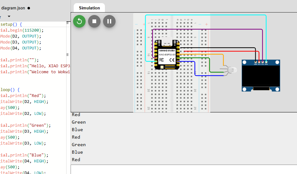
📈2. Simulation of the circuit:
In this stage, I analyzed the program used to control the OLED display and the RGB LED module with the XIAO ESP32-S3. By reviewing the code, I was able to understand how the display is initialized and updated, as well as how the RGB LED receives signals to generate different colors.
The structure of the code allowed me to clearly identify how both output devices are managed at the same time, including the functions used to display information
⚙️3. Code visualization
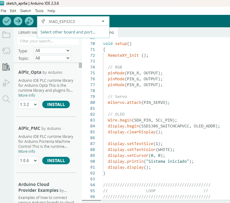
The code visualization for this project was focused on integrating multiple input and output devices with the XIAO ESP32-S3 embedded board. The program was developed in Arduino IDE and organized to manage the ultrasonic sensor, DHT11 temperature sensor, and OLED display simultaneously. The code continuously collected data from the sensors, processed the readings, and displayed the information on the OLED screen in real time. This implementation demonstrated how the embedded system could interact with both sensors and output devices to create a functional and user-friendly interface application.
⚙️4. Programming Process-Smart Output System with OLED Display and sensors
Programming Process: Potentiometer Reading with Arduinio IDE
The programming process for the Smart Output System was developed using the XIAO ESP32-S3 microcontroller in Arduino IDE. The system integrated multiple components including an OLED display, ultrasonic sensor, DHT11 temperature sensor, The code was structured to continuously read sensor data, process the information, and control the outputs according to the programmed conditions. Libraries for the OLED display, DHT11 sensor, and servo motor were included to simplify communication and device management.
Code Writing in Arduino IDE
/*
   ===================================================
   XIAO ESP32-C3 + DHT11 + OLED + RemoteXY
   ===================================================

   SWITCH ON:
   - Muestra temperatura en OLED
   - Mueve el tacómetro de RemoteXY

   SWITCH OFF:
   - OLED muestra solamente OFF
*/

//////////////////////////////////////////////
//              REMOTEXY                   //
//////////////////////////////////////////////

#define REMOTEXY_MODE__WIFI_CLOUD

#include

#define REMOTEXY_WIFI_SSID "Hjian"
#define REMOTEXY_WIFI_PASSWORD "3dvikajy"
#define REMOTEXY_CLOUD_SERVER "cloud.remotexy.com"
#define REMOTEXY_CLOUD_PORT 6376
#define REMOTEXY_CLOUD_TOKEN "bf70709092852953fd4170ba1e0c6b53"
#define REMOTEXY_ACCESS_PASSWORD "1234"

#include

//////////////////////////////////////////////
//              LIBRERIAS                  //
//////////////////////////////////////////////

#include
#include

#include
#include

//////////////////////////////////////////////
//              OLED CONFIG                //
//////////////////////////////////////////////

#define SCREEN_WIDTH 128
#define SCREEN_HEIGHT 64

Adafruit_SSD1306 display(SCREEN_WIDTH, SCREEN_HEIGHT, &Wire, -1);

//////////////////////////////////////////////
//               DHT11                     //
//////////////////////////////////////////////

#define DHTPIN 2
#define DHTTYPE DHT11

DHT dht(DHTPIN, DHTTYPE);

//////////////////////////////////////////////
//               I2C                       //
//////////////////////////////////////////////

#define SDA_PIN 6
#define SCL_PIN 7

//////////////////////////////////////////////
//           REMOTEXY GUI                  //
//////////////////////////////////////////////

#pragma pack(push, 1)
uint8_t const PROGMEM RemoteXY_CONF_PROGMEM[] =
{
  255,1,0,4,0,100,0,19,0,0,0,70,65,66,80,69,82,85,0,31,
  1,106,200,1,1,4,0,2,28,12,44,22,0,121,26,31,31,79,78,0,
  79,70,70,0,71,14,47,72,72,56,0,36,24,104,0,0,0,0,0,0,
  200,66,0,0,160,65,0,0,32,65,0,0,0,64,24,0,129,6,124,93,
  14,64,189,70,65,66,32,65,67,65,68,69,77,89,0,129,28,144,48,21,
  64,1,50,48,50,54,0
};

struct {

  uint8_t switch_01;

  float instrument_01;

  uint8_t connect_flag;

} RemoteXY;

#pragma pack(pop)

//////////////////////////////////////////////
//                 SETUP                   //
//////////////////////////////////////////////

void setup()
{
  Serial.begin(115200);

  // RemoteXY
  RemoteXY_Init();

  // DHT11
  dht.begin();

  // I2C
  Wire.begin(SDA_PIN, SCL_PIN);

  // OLED
  if(!display.begin(SSD1306_SWITCHCAPVCC, 0x3C))
  {
    Serial.println("OLED no encontrada");
    while(1);
  }

  display.clearDisplay();
  display.display();

  Serial.println("Sistema iniciado");
}

//////////////////////////////////////////////
//                  LOOP                   //
//////////////////////////////////////////////

void loop()
{
  // RemoteXY
  RemoteXY_Handler();

  //////////////////////////////////////////
  // SWITCH ON
  //////////////////////////////////////////

  if(RemoteXY.switch_01 == 1)
  {
    // Leer temperatura
    float temperatura = dht.readTemperature();

    // Verificar lectura
    if(!isnan(temperatura))
    {
      //////////////////////////////////////
      // TACOMETRO REMOTEXY
      //////////////////////////////////////

      RemoteXY.instrument_01 = temperatura;

      //////////////////////////////////////
      // SERIAL
      //////////////////////////////////////

      Serial.print("Temperatura: ");
      Serial.print(temperatura);
      Serial.println(" C");

      //////////////////////////////////////
      // OLED
      //////////////////////////////////////

      display.clearDisplay();

      display.setTextColor(SSD1306_WHITE);

      // TITULO
      display.setTextSize(1);

      display.setCursor(10, 5);
      display.println("FAB ACADEMY 2026");

      display.drawLine(0, 18, 128, 18, SSD1306_WHITE);

      // TEMPERATURA
      display.setTextSize(2);

      display.setCursor(10, 30);
      display.println("TEMP:");

      display.setCursor(20, 50);
      display.print(temperatura);
      display.print(" C");

      display.display();
    }
  }

  //////////////////////////////////////////
  // SWITCH OFF
  //////////////////////////////////////////

  else
  {
    // Reinicia tacómetro
    RemoteXY.instrument_01 = 0;

    // OLED OFF
    display.clearDisplay();

    display.setTextColor(SSD1306_WHITE);
    display.setTextSize(4);

    display.setCursor(15, 20);
    display.println("OFF");

    display.display();

    Serial.println("OFF");
  }

  delay(1000);
}
```
Programming Process: RemoteXY + OLED + RGB + Servo (ESP32-S3)
4.1. Libraries and Configuration
#include <WiFi.h>
#include <RemoteXY.h>
#include <Wire.h>
#include <DHT.h>
#include <Adafruit_GFX.h>
#include <Adafruit_SSD1306.h>

#define REMOTEXY_WIFI_SSID "Hjian"
#define REMOTEXY_WIFI_PASSWORD "3dvikajy"

#define SCREEN_WIDTH 128
#define SCREEN_HEIGHT 64

#define DHTPIN 2
#define DHTTYPE DHT11

#define SDA_PIN 6
#define SCL_PIN 7

Adafruit_SSD1306 display(SCREEN_WIDTH, SCREEN_HEIGHT, &Wire, -1);

DHT dht(DHTPIN, DHTTYPE);
- WiFi & RemoteXY: Enable wireless communication between the mobile application and the XIAO ESP32-C3 board. 🌐
- Wire: Handles I2C communication for the OLED display.
- DHT Library: Reads temperature data from the DHT11 sensor.
- Adafruit_GFX & Adafruit_SSD1306: Control graphics and text visualization on the OLED screen.
- OLED Configuration: Defines a 128x64 pixel display resolution.
- DHT11 Configuration: Assigns the sensor to pin 2 for temperature measurements.
- I2C Pins: Custom SDA and SCL pins were configured for the XIAO ESP32-C3 board.
4.2. Setup Configuration
void setup()
{
  Serial.begin(115200);

  // RemoteXY initialization
  RemoteXY_Init();

  // Initialize DHT11 sensor
  dht.begin();

  // Initialize I2C communication
  Wire.begin(SDA_PIN, SCL_PIN);

  // Initialize OLED display
  if(!display.begin(SSD1306_SWITCHCAPVCC, 0x3C))
  {
    Serial.println("OLED not found");
    while(1);
  }

  display.clearDisplay();
  display.display();

  Serial.println("System initialized");
}
- Serial Communication: Starts serial monitoring at 115200 baud rate for debugging and data visualization.
- RemoteXY Initialization: Establishes communication between the mobile application and the embedded board. 📲
- DHT11 Initialization: Activates the temperature sensor for environmental data acquisition.
- I2C Communication: Configures the SDA and SCL pins used by the OLED display.
- OLED Initialization: Verifies if the OLED display is correctly connected and ready to operate.
- Display Cleaning: Clears previous graphics and prepares the OLED for real-time information display.
4.3. Remote Control Logic
void loop()
{
  // Handle RemoteXY communication
  RemoteXY_Handler();

  // SWITCH ON
  if(RemoteXY.switch_01 == 1)
  {
    float temperatura = dht.readTemperature();

    if(!isnan(temperatura))
    {
      // Update RemoteXY instrument
      RemoteXY.instrument_01 = temperatura;

      Serial.print("Temperatura: ");
      Serial.println(temperatura);
    }
  }

  // SWITCH OFF
  else
  {
    // Reset RemoteXY instrument
    RemoteXY.instrument_01 = 0;

    Serial.println("OFF");
  }

  delay(1000);
}
- RemoteXY_Handler(): Continuously updates communication between the mobile interface and the XIAO ESP32-C3 board. 📡
- ON/OFF Switch: Allows the user to remotely enable or disable the system from the RemoteXY application.
- Temperature Reading: When the switch is ON, the DHT11 sensor measures the ambient temperature.
- Remote Instrument: The temperature value is sent to the tachometer widget in the RemoteXY interface for real-time monitoring.
- Serial Monitoring: Displays temperature values and system status for debugging purposes.
- OFF State: Resets the tachometer value and disables data visualization when the switch is turned OFF.
4.4. OLED Display Update
// OLED DISPLAY UPDATE

display.clearDisplay();

display.setTextColor(SSD1306_WHITE);

// Title
display.setTextSize(1);

display.setCursor(10, 5);
display.println("FAB ACADEMY 2026");

display.drawLine(0, 18, 128, 18, SSD1306_WHITE);

// Temperature
display.setTextSize(2);

display.setCursor(10, 30);
display.println("TEMP:");

display.setCursor(20, 50);
display.print(temperatura);
display.print(" C");

display.display();
- clearDisplay(): Clears previous information from the OLED screen before updating new data.
- Text Configuration: Defines text color and size for better visualization on the display.
- Custom Title: Displays the “FAB ACADEMY 2026” title as part of the interface design. 🖥️
- Graphic Elements: A horizontal line is drawn to visually separate the title from the sensor information.
- Temperature Visualization: The OLED screen shows real-time temperature values obtained from the DHT11 sensor.
- display.display(): Sends all graphics and text data to the OLED screen for visualization.
4.5. Sensor Integration – Ultrasonic Sensor and DHT11
// DHT11 CONFIGURATION

#define DHTPIN 2
#define DHTTYPE DHT11

DHT dht(DHTPIN, DHTTYPE);

// TEMPERATURE READING

float temperatura = dht.readTemperature();

// VALIDATION

if(!isnan(temperatura))
{
  Serial.print("Temperatura: ");
  Serial.print(temperatura);
  Serial.println(" C");
}
- DHT11 Sensor: Used to measure ambient temperature in real time. 🌡️
- DHT Library: Simplifies communication between the XIAO ESP32-C3 and the temperature sensor.
- Temperature Reading: The system continuously acquires temperature values from the DHT11 sensor.
- Data Validation: The isnan() function verifies that the sensor reading is valid before displaying the information.
- Serial Monitoring: Temperature data is sent to the serial monitor for debugging and visualization purposes.
- Ultrasonic Sensor: The ultrasonic sensor was integrated as an input device to detect distance and object presence within the embedded system.
4.6. Loop Execution
void loop()
{
  // Update RemoteXY communication
  RemoteXY_Handler();

  // Verify switch state
  if(RemoteXY.switch_01 == 1)
  {
    float temperatura = dht.readTemperature();

    if(!isnan(temperatura))
    {
      RemoteXY.instrument_01 = temperatura;

      // OLED update
      display.clearDisplay();
      display.display();
    }
  }
  else
  {
    // OFF mode
    RemoteXY.instrument_01 = 0;

    display.clearDisplay();

    display.setTextSize(4);
    display.setCursor(15, 20);
    display.println("OFF");

    display.display();
  }

  delay(1000);
}
- Main Loop: Continuously executes the program instructions while the embedded system is powered on. 🔄
- RemoteXY Communication: Updates the connection between the mobile interface and the XIAO ESP32-C3 board in real time.
- Switch Verification: Checks whether the RemoteXY switch is in ON or OFF mode.
- Sensor Reading: Reads temperature data from the DHT11 sensor when the system is active.
- OLED Update: Refreshes the OLED display with temperature information or OFF status depending on the switch state.
- Delay Function: A one-second delay stabilizes sensor readings and display updates.
✅4.7 Program Objective
The main objective of this program was to develop an interactive embedded application using the XIAO ESP32-C3 microcontroller capable of interfacing with both input and output devices. The system was designed to acquire environmental data from sensors, process the information in real time, and display the results through a user-friendly interface. Additionally, the project aimed to establish wireless communication between the embedded board and a mobile application using RemoteXY, allowing remote monitoring and control of the system.
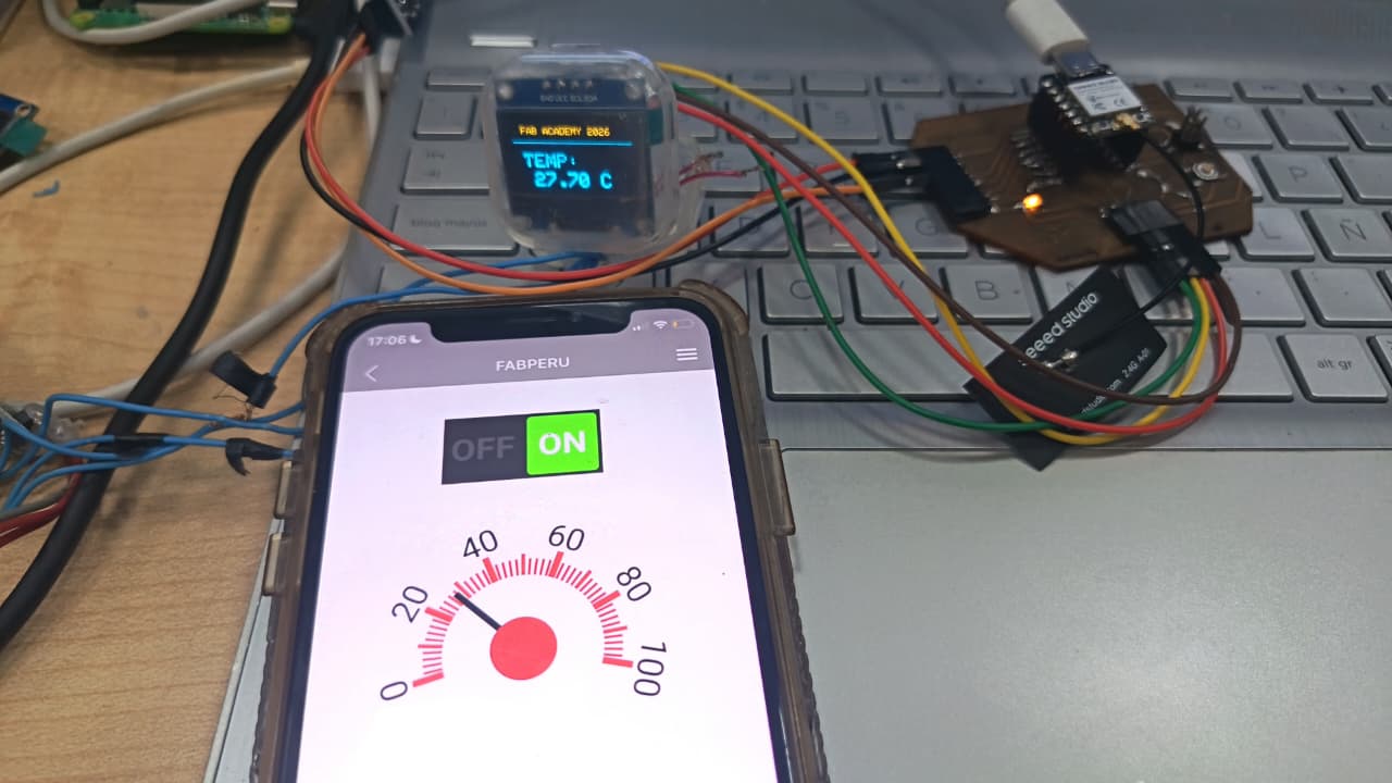
⚙️4.8. OLED display,SENSOR DHT11, ULTRASONIC SENSOR (SSD1306)
The OLED display (SSD1306) was used as the main output device of the system, allowing real-time visualization of information generated by the embedded board. The display showed temperature readings obtained from the DHT11 sensor and provided a clear interface for monitoring the system status. When the RemoteXY switch was activated, the OLED displayed the measured temperature together with a custom title, while in OFF mode the display only showed the word “OFF”. The SSD1306 display communicated with the XIAO ESP32-C3 using the I2C protocol, making the connection simple and efficient.
The DHT11 sensor was integrated as the main environmental input device for temperature monitoring. The sensor continuously measured ambient temperature values, which were processed by the microcontroller and visualized on both the OLED display and the RemoteXY mobile interface. The program also verified that the sensor readings were valid before updating the outputs, improving the reliability of the system. This sensor allowed the project to demonstrate real-time data acquisition and monitoring within an embedded application.
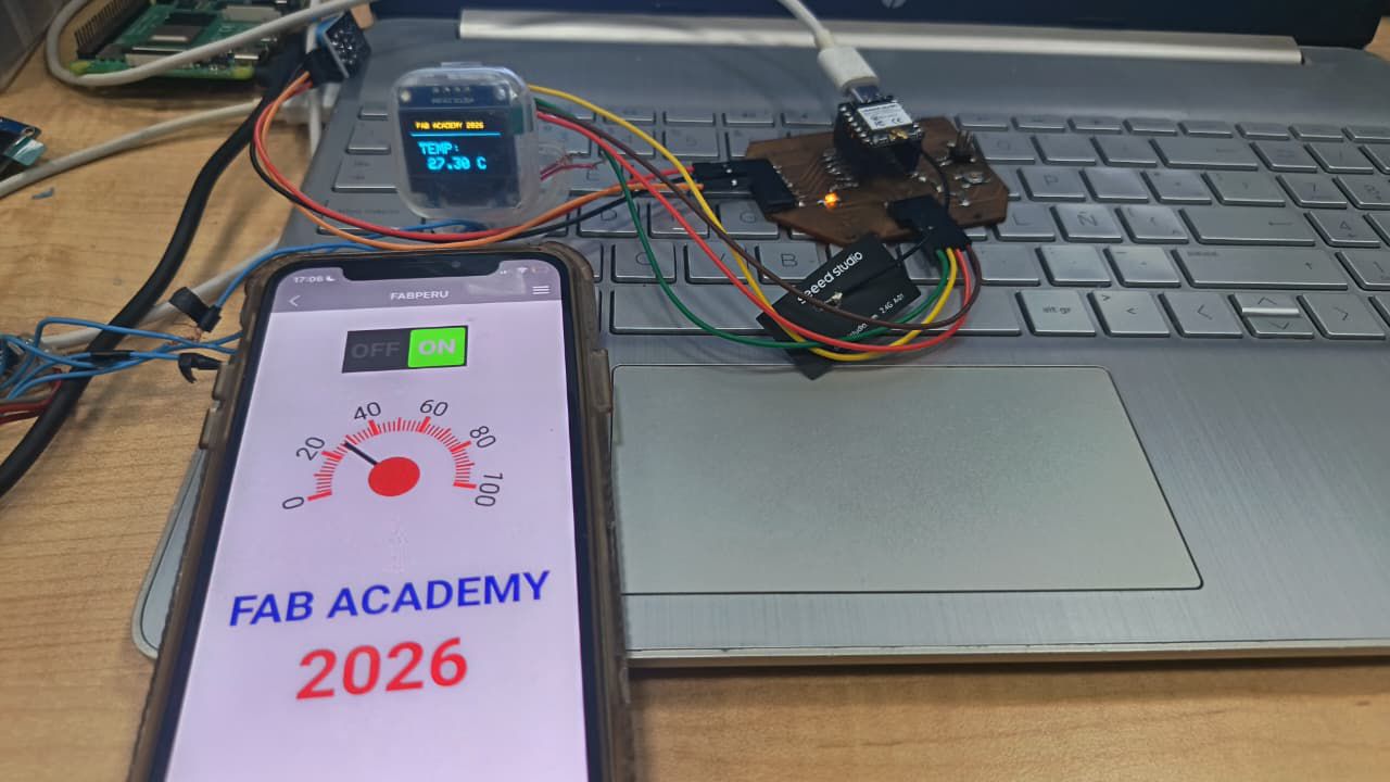
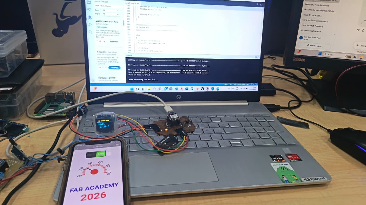
⚙️ I tested in PCB
In this stage, I tested the circuit directly on the fabricated PCB using the XIAO ESP32 S3 as the main microcontroller. After assembling the components, including the OLED display and the SG90 servo motor, I powered the board and uploaded the program.
I verified the correct operation of the output devices by observing the information displayed on the OLED and the movement of the servo motor. This allowed me to confirm that the connections, control signals, and overall system performance were working properly, ensuring proper synchronization between visual and mechanical outputs. ⚙️📟
📟Individual Reflections
Through this individual assignment, I learned how to develop an interactive embedded application capable of connecting sensors, displays, and wireless communication into a single functional system. Working with the XIAO ESP32-C3 allowed me to improve my understanding of embedded programming, sensor integration, and real-time data visualization. I also gained experience using RemoteXY to create a mobile interface that could remotely control and monitor the system through WiFi communication.
One of the most important lessons from this assignment was understanding how software and hardware interact together to create smart systems. Integrating the DHT11 sensor, ultrasonic sensor, and OLED display required careful configuration of libraries, communication protocols, and program logic. Additionally, debugging the system and ensuring stable communication between the devices helped me improve my problem-solving skills and confidence in developing embedded applications for digital fabrication projects.
Files
Here are the project files available for download:
- ARDUINO IDE CODE + REMOTE XY: Download .ino