Week 09
Input Devices
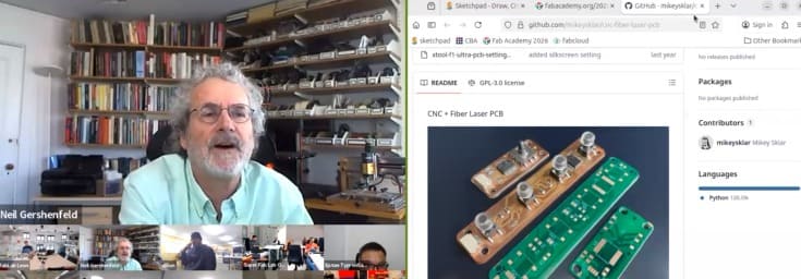
Class with Neil
During Week 09 – Input Devices, the main objective was to design and integrate input systems that allow the electronic board to receive data from the external environment. This process focused on incorporating sensors and components capable of detecting physical changes such as light, motion, or touch, and converting them into readable electronic signals.
The workflow included key stages such as sensor selection, circuit design, PCB integration, programming, and signal testing. Through this process, I learned how to properly interface input devices with a microcontroller, considering aspects such as signal conditioning, voltage levels, and data acquisition.
This assignment allowed me to better understand how electronic systems interact with real-world inputs, strengthening my skills in sensor integration, programming, and embedded system design.
Have you answered these questions?
- I. Linked to the group assignment page. ✅
- II.Documented what you learned from interfacing an input device(s) to your microcontroller and optionally, how the physical property relates to the measured results. ✅
- III.Documented your design and fabrication process or linked to the board you made in a previous assignment. ✅
- IV. Explaind how your code works.✅
- V. Explained any problems and how you fixed them ✅
- VI.Included original design files and source code.✅
- VII.Included a ‘hero shot’ of your board.✅
Hero Shot
For this section, I created a visual composition using a photograph taken at the Faculty of Architecture of the National University of Engineering. In the image, I appear interacting with a scaled version of the Lanzón Monolith, which helps to give a better sense of proportion and presence of the piece in a real environment. This approach allowed me to connect my digital fabrication work with a physical and contextual setting.
To enhance the visual impact, I edited the image in Photoshop, integrating the 3D model into the scene in a realistic way. I adjusted lighting, perspective, and shadows so that the piece blends naturally with the environment. This final composition not only presents the project in a more engaging way but also reinforces the concept and cultural inspiration behind the design.

Group Assignment:
°Probe an input device(s)'s analog levels and digital signals (As a minimum, you should demonstrate the use of a multimeter and an oscilloscope.)
° Document your work on the group work page and reflect on your individual page what you learned
Group Assignment Sumary
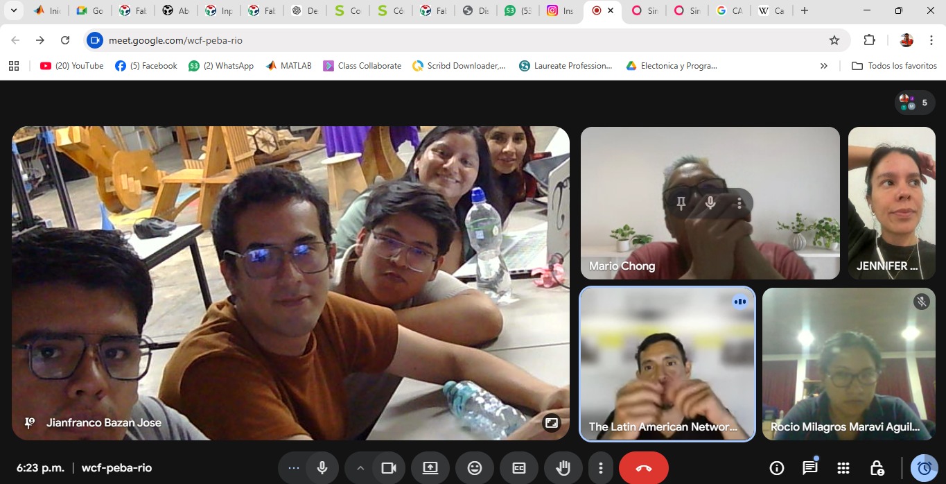
For the group assignment, we met at the FABLAB UNI, where we had the opportunity to test and validate input devices using a PCB designed by Adrian Torres This board allowed us to experiment with different sensors, specifically an ultrasonic sensor and an LDR sensor, enabling us to analyze how input signals are captured and processed.
As a team, we focused on understanding how these sensors interact with the microcontroller, exploring their behavior and response under different conditions. We tested how the ultrasonic sensor measures distance and how the LDR detects variations in light intensity, observing the changes in output signals.
Through this collaborative experience, we gained a better understanding of how input devices work in real applications, as well as how to properly integrate and test them within an electronic system. This was key to strengthening our knowledge for developing our individual projects involving sensor-based inputs. ⚙️💡
Here is the link to learn more about the group project.
🔍 LDR Sensor Module - 4 pin
During this assignment, I gained practical experience working with input devices, specifically the ultrasonic sensor and the LDR sensor. We started by programming the ultrasonic sensor and used the Serial Monitor in the Arduino IDE to observe the distance data in real time. This allowed me to clearly understand how the sensor captures and transmits information.
Additionally, we used the Serial Plotter, which provided a graphical representation of the data. This visualization made it easier to analyze how the values changed over time and helped me better interpret the sensor behavior.
Overall, this experience helped me understand how to read, analyze, and visualize input data from sensors, reinforcing my knowledge in embedded programming and real-world interaction with electronic systems. ⚙️📊
Individual Group Assignment Reflection
During the group assignment for the Input Devices week, we worked with an instructor-provided microcontroller board FAB XIAO developed by Adrian Torres to better understand how input devices communicate with embedded systems. In this activity, we tested a temperature sensor connected to the board and used Arduino IDE to upload the program and monitor the sensor data through the Serial Monitor in real time. This experience helped me understand how a microcontroller reads sensor information, processes the signals, and converts them into readable digital data for user monitoring and analysis. Additionally, the assignment reinforced my understanding of sensor integration, serial communication, debugging, and the importance of combining both hardware and software tools to validate the operation of embedded electronic systems.
Individual Assignment
° Measure something: add a sensor to a microcontroller board that you have designed and read it.
Introduction
In this individual assignment, I focused on working with different input devices to understand how electronic systems can interact with the real world. For this purpose, I used two sensors: the HC-SR04 Ultrasonic Sensor,DHT11 Temperature Sensor,.
Each of these sensors allowed me to explore different types of input signals. The ultrasonic sensor was used to measure distance, the TCRT5000 helped detect proximity or line tracking based on infrared reflection, and the touch sensor enabled interaction through physical contact. Notably, the Ultrasonic will be especially important for my final project, as it will be used as part of the detection system.
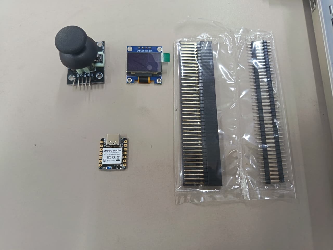
PCB Components List
For this assignment, I used the SEEED STUDIO XIAO RP2040 as the main controller,a Header 01x05 for connections. I also integrated three sensors: the TTP223 touch sensor, the HC-SR04 ultrasonic sensor, and the Ultrasonic Senor HC-SR04 , allowing me to capture and process different types of input signals. ⚙️📡
| Item | Component | Amount |
|---|---|---|
| 1 | SEEED STUDIO XIAO RP2040 | 1 |
| 2 | Header 01x05 P2.54 mm Horizontal SMD | 4 |
| 4 | HC-SR04 Ultrasonic Senor | 1 |
| 5 | DHT11 Temperature Sensor | 1 |
📟PCB Components
The PCB integrates the SEEED STUDIO XIAO RP2040 as the main microcontroller, connected to supporting components and external interfaces for sensor integration. In this project, I incorporated an HC-SR04 ultrasonic sensor for distance measurement and a humidity and temperature sensor to collect environmental data in real time. These input devices allow the microcontroller to read and process different types of sensor information, transforming physical measurements into digital data that can later be monitored, analyzed, or used for interactive embedded system applications. Together, the PCB and sensors create a functional electronic system focused on environmental sensing and distance detection. ⚙️📡⚙️📡
⚙️1. Programming Process: Ultrasonic sensor(Arduino IDE)
Programming Process: Potentiometer Reading with Arduinio IDE
⚙️1.1 I made a Simple Scetch
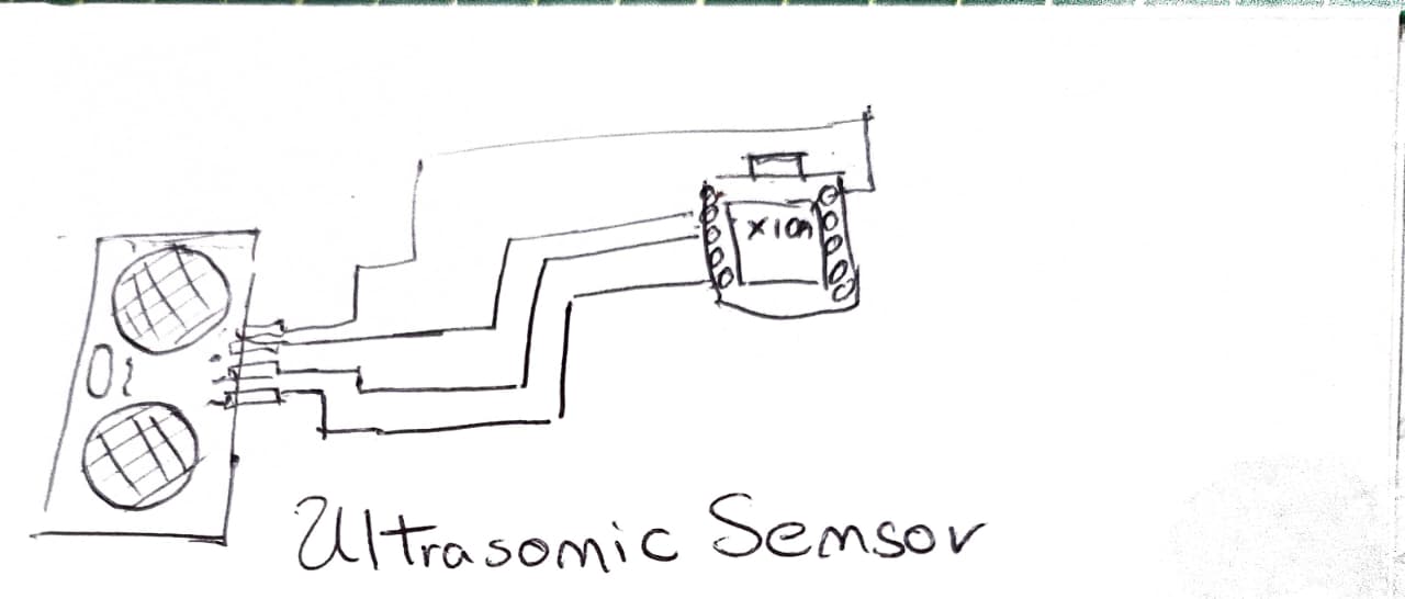
In this step, I created a simple sketch to represent the connection between the XIAO ESP32 S3 and the DHT11 temperature and humidity sensor. The diagram defines the basic wiring, connecting VCC to 3.3V, GND to GND, and the DATA pin to a digital GPIO of the microcontroller.
This sketch helped me clearly understand how the sensor communicates with the ESP32 S3 using a single data line, where both temperature and humidity values are transmitted. It also allowed me to verify the correct pin configuration before implementing the physical circuit.🌡️💧⚙️
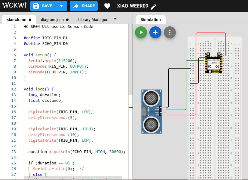
📈1.2 Simulation of the circuit:
Before testing the physical hardware, I simulated the electronic circuit using the Wokwi platform to verify the behavior of the SEEED STUDIO XIAO RP2040 together with the HC-SR04 ultrasonic sensor. In the simulation, the ultrasonic sensor was connected to the microcontroller using the TRIG and ECHO pins to measure distance values. The Arduino code generated the trigger pulse, received the echo response, and calculated the detected distance based on the travel time of the ultrasonic signal. Through the Serial Monitor, the measured values could be visualized in real time, allowing me to confirm that the sensor communication and signal processing were functioning correctly before implementing the circuit on the real PCB. This simulation stage helped me validate the wiring connections, debug the code logic, and better understand how the ultrasonic sensor interacts with the microcontroller in an embedded input device system.
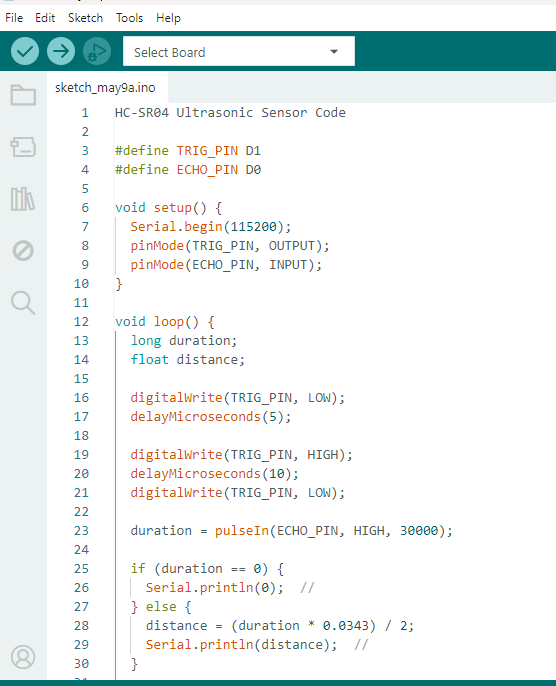
⚙️1.3 Code visualization
The program for the HC-SR04 ultrasonic sensor was developed and visualized in the Arduino IDE environment using the SEEED STUDIO XIAO RP2040 microcontroller. The code defines the TRIG and ECHO pins, initializes serial communication, and continuously measures the distance detected by the ultrasonic sensor. During execution, the microcontroller sends a short trigger pulse to the sensor, receives the echo signal, and calculates the distance based on the ultrasonic wave travel time. The measured values are then displayed in the Serial Monitor, allowing real-time visualization of the sensor data. This programming process helped me understand how input devices communicate with microcontrollers through digital signals and how sensor data can be processed and monitored using embedded programming tools.
1.4 Code Writing in Arduino IDE
HC-SR04 Ultrasonic Sensor Code

#define TRIG_PIN D1
#define ECHO_PIN D0

void setup() {
  Serial.begin(115200);
  pinMode(TRIG_PIN, OUTPUT);
  pinMode(ECHO_PIN, INPUT);
}

void loop() {
  long duration;
  float distance;

  digitalWrite(TRIG_PIN, LOW);
  delayMicroseconds(5);

  digitalWrite(TRIG_PIN, HIGH);
  delayMicroseconds(10);
  digitalWrite(TRIG_PIN, LOW);

  duration = pulseIn(ECHO_PIN, HIGH, 30000);

  if (duration == 0) {
    Serial.println(0);  //
  } else {
    distance = (duration * 0.0343) / 2;
    Serial.println(distance);  //
  }

  delay(100);
}
Programming Process: HC-SR04 Ultrasonic Sensor (Arduino IDE)
1.4.1 Define Pins
#define TRIG_PIN D1
#define ECHO_PIN D0
- TRIG_PIN: Used to send the ultrasonic pulse signal.
- ECHO_PIN: Used to receive the reflected signal from the object.
1.4.2 Setup Configuration
void setup() {
  Serial.begin(115200);
  pinMode(TRIG_PIN, OUTPUT);
  pinMode(ECHO_PIN, INPUT);
}
- Serial.begin(115200): Initializes serial communication.
- pinMode: Configures TRIG as output and ECHO as input.
1.4.3 Generate Ultrasonic Pulse
digitalWrite(TRIG_PIN, LOW);
delayMicroseconds(5);

digitalWrite(TRIG_PIN, HIGH);
delayMicroseconds(10);
digitalWrite(TRIG_PIN, LOW);
- Sends a short pulse (10 microseconds) to trigger the ultrasonic sensor.
1.4.4 Read Echo Signal
duration = pulseIn(ECHO_PIN, HIGH, 30000);
- pulseIn(): Measures the time the signal stays HIGH.
- Timeout is set to avoid blocking if no signal is received.
1.4.5 Calculate Distance
if (duration == 0) {
  Serial.println(0);
} else {
  distance = (duration * 0.0343) / 2;
  Serial.println(distance);
}
- Converts time into distance using the speed of sound.
- Divided by 2 because the signal travels to the object and back.
1.4.6 Loop Execution
delay(100);
- Adds a small delay between measurements for stability.
✅1.4.7 Program Objective
Measure the distance between the sensor and an object using ultrasonic waves, and display the result in real time through the Serial Monitor.
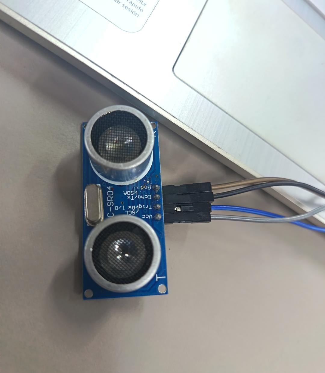
⚙️1.5 HC-SR04 Ultrasonic Sensor
The HC-SR04 Ultrasonic Sensor is a sensor used to measure distance without contact using ultrasonic waves. It sends a sound wave and calculates the distance based on the time it takes to bounce back from an object. Key specifications: operates at 5V, measures from 2 cm to 4 m, has an accuracy of ±3 mm, and uses a 40 kHz frequency. It has 4 pins: VCC, GND, TRIG (signal output), and ECHO (signal input).
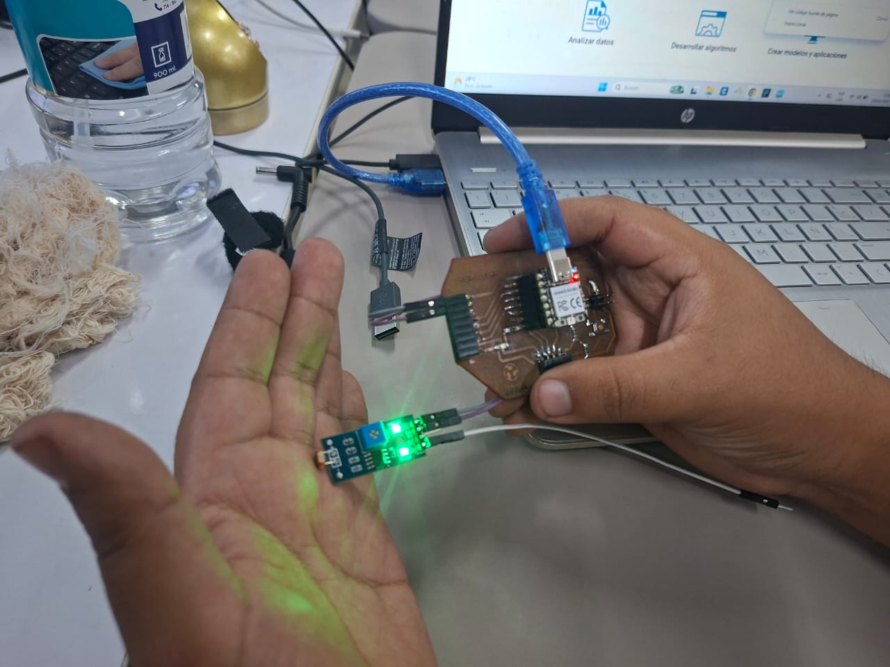
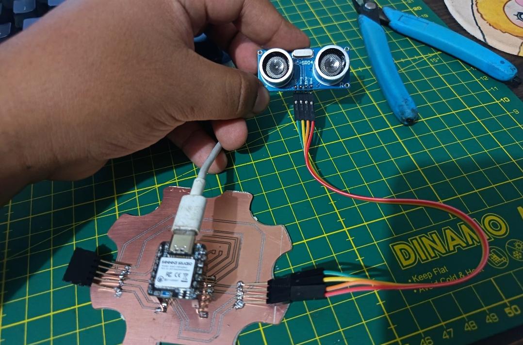
⚙️1.6 I tasted in PCB
After validating the circuit through simulation, I proceeded to test the system using my custom PCB based on the SEEED STUDIO XIAO RP2040. The HC-SR04 ultrasonic sensor and the humidity and temperature sensor were connected directly to the board to verify real hardware communication and sensor functionality. Using the Arduino IDE and Serial Monitor, I was able to observe the sensor readings in real time, confirming that the PCB connections, power distribution, and signal communication were working correctly. This stage allowed me to validate the transition from simulation to physical implementation while also testing the reliability of the PCB design and the interaction between the microcontroller and the input devices.
⚙️2. Programming Process: DHT11 temperature and humidity sensor(Arduino IDE)
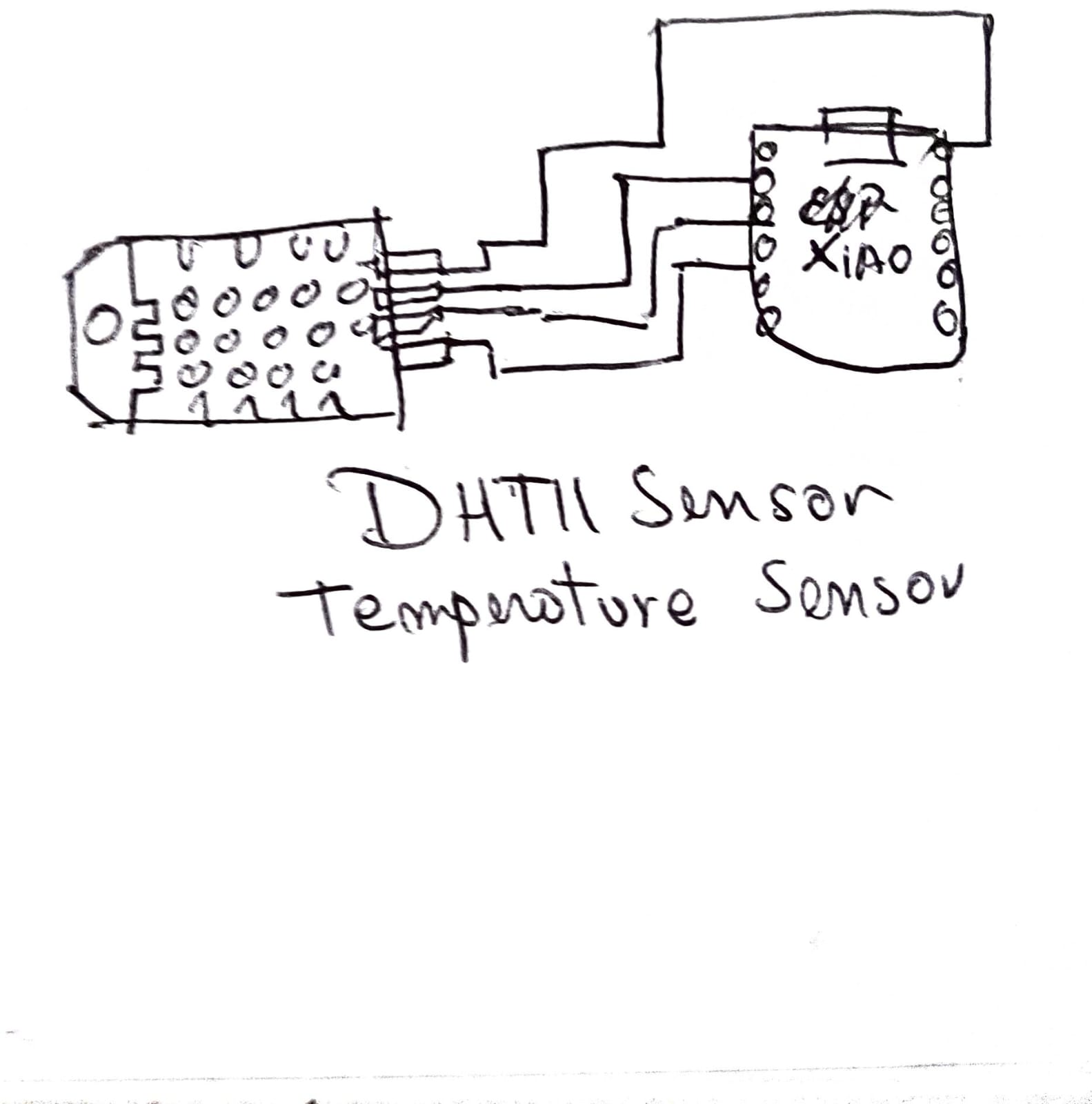
⚙️2.1 I made a Simple Scetch
Before designing the final electronic connections, I created a simple sketch to organize the general structure of the system and visualize how the components would interact with each other. In this sketch, I identified the SEEED STUDIO XIAO RP2040 as the central microcontroller and mapped the connections for the DHT11 temperature and humidity sensor. This preliminary drawing helped me understand the required input pins, power connections, and signal flow between the sensor and the PCB. Additionally, the sketch served as an initial planning step before moving to the simulation and programming stages, making the development process more organized and easier to understand.
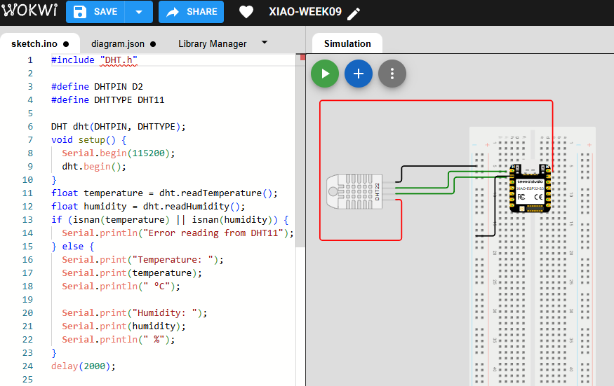
📈2.2 Simulation of the circuit:
Before implementing the physical hardware, I simulated the circuit in the Wokwi platform using the DHT11 temperature and humidity sensor connected to the SEEED STUDIO XIAO RP2040 microcontroller. This simulation allowed me to verify the communication between the sensor and the microcontroller while testing the Arduino code in a virtual environment. Through the Serial Monitor available in Wokwi, I was able to visualize the temperature and humidity readings in real time, confirming that the sensor data was being processed correctly. This stage helped me validate the wiring connections, the sensor library configuration, and the logic of the embedded program before testing the circuit on the physical PCB. Additionally, the simulation improved my understanding of how digital environmental sensors communicate with microcontrollers and transmit data for monitoring and analysis applications.
⚙️2.3 Code visualization
The program for the DHT11 temperature and humidity sensor was developed and visualized in the Arduino IDE using the SEEED STUDIO XIAO RP2040 microcontroller. The code initializes the DHT11 sensor library, configures the communication pin, and continuously reads the environmental data generated by the sensor. During execution, the microcontroller processes both the temperature and humidity values and sends the information to the Serial Monitor for real-time visualization. This programming stage helped me understand how digital sensors communicate with embedded systems and how environmental data can be acquired, processed, and monitored through Arduino-based programming.
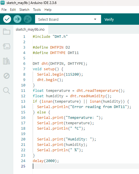
2.4Code Writing in Arduino IDE - DHT11 temperature and humidity sensor Code
#include "DHT.h"

#define DHTPIN D2
#define DHTTYPE DHT11

DHT dht(DHTPIN, DHTTYPE);
void setup() {
  Serial.begin(115200);
  dht.begin();
}
float temperature = dht.readTemperature();
float humidity = dht.readHumidity();
if (isnan(temperature) || isnan(humidity)) {
  Serial.println("Error reading from DHT11");
} else {
  Serial.print("Temperature: ");
  Serial.print(temperature);
  Serial.println(" °C");

  Serial.print("Humidity: ");
  Serial.print(humidity);
  Serial.println(" %");
}
delay(2000);
Programming Process: DHT11 Temperature & Humidity Sensor (Arduino IDE)
2.4.1 Import Required Library
#include "DHT.h"
- DHT library: Used to interface with the DHT11 sensor and read temperature and humidity values.
2.4.2 Define Sensor Type and Pin
#define DHTPIN D2
#define DHTTYPE DHT11

DHT dht(DHTPIN, DHTTYPE);
- DHTPIN: Digital pin where the sensor is connected.
- DHTTYPE: Specifies the sensor model (DHT11).
- DHT object: Initializes the sensor.
2.4.3 Setup Configuration
void setup() {
  Serial.begin(115200);
  dht.begin();
}
- Serial.begin(115200): Starts serial communication.
- dht.begin(): Initializes the sensor.
2.4.4 Read Sensor Data
float temperature = dht.readTemperature();
float humidity = dht.readHumidity();
- Reads temperature in Celsius and humidity percentage from the sensor.
2.4.5 Validate and Display Data
if (isnan(temperature) || isnan(humidity)) {
  Serial.println("Error reading from DHT11");
} else {
  Serial.print("Temperature: ");
  Serial.print(temperature);
  Serial.println(" °C");

  Serial.print("Humidity: ");
  Serial.print(humidity);
  Serial.println(" %");
}
- isnan(): Checks if the reading failed.
- If valid, the data is printed to the Serial Monitor.
2.4.6 Loop Delay
delay(2000);
- The DHT11 sensor requires a delay between readings (minimum 1–2 seconds).
✅ 2.4.7 Program Objective
Measure environmental temperature and humidity using the DHT11 sensor and display the values in real time through the Serial Monitor. This allows monitoring environmental conditions for further analysis.
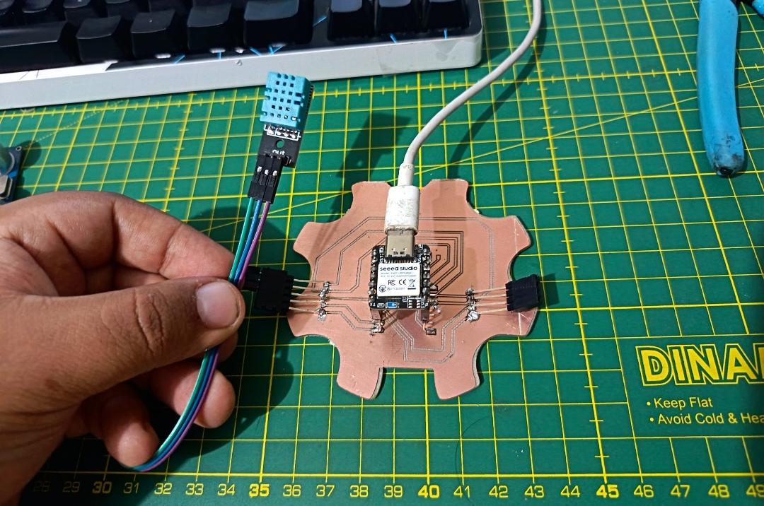
3. I tasted in PCB
In this stage, I tested the DHT11 temperature and humidity sensor directly on the fabricated PCB using the XIAO ESP32 S3 as the main microcontroller. After connecting the sensor to the corresponding power, ground, and data pin, I uploaded the program to read temperature and humidity values.
I monitored the output through the Serial Monitor, where I was able to observe real-time environmental data. This allowed me to verify that the sensor was correctly connected and communicating properly with the microcontroller.
4. Individual Assignment Reflection
This assignment helped me better understand how input devices interact with embedded systems through sensors and microcontrollers. By working with the SEEED STUDIO XIAO RP2040 together with the HC-SR04 ultrasonic sensor and the DHT11 temperature and humidity sensor, I learned how to acquire real-world data, process sensor signals, and visualize information using the Arduino IDE Serial Monitor. Throughout the process, I explored circuit simulation in Wokwi, sensor integration on a custom PCB, and embedded programming for reading both digital and distance-based inputs. Additionally, this assignment improved my understanding of how environmental and proximity sensors communicate with microcontrollers and how these technologies can be applied in interactive and intelligent electronic systems.
Files
Here are the project files available for download:
- Arduino IDE Ultrasonic Sensor: Download .ino
- Arduino IDE DHT11 Temperature Sensor: Download .ino