Week 10
Output Devices
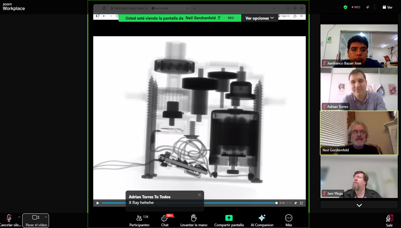
Class with Neil
During Week 10 – Output Devices, the main objective was to design and integrate systems that allow the electronic board to interact with the external environment by generating outputs. This process focused on using components such as actuators, displays, and indicators that can respond to signals from the microcontroller.
The workflow included key stages such as output device selection, circuit design, PCB integration, programming, and functional testing. Through this process, I learned how to properly control output devices from a microcontroller, considering aspects such as voltage requirements, current consumption, and signal control.
This assignment allowed me to better understand how electronic systems can produce visible or physical responses, strengthening my skills in actuator control, programming, and embedded system design. ⚙️💡
Have you answered these questions?
- I. Linked to the group assignment page. ✅
- II.Documented how you determined power consumption of an output device with your group. ✅
- III.Documented what you learned from interfacing output device(s) to microcontroller and controlling the device(s). ✅
- IV. Linked to the board you made in a previous assignment or documented your design and fabrication process if you made a new board.✅
- V. Explained how your code works. ✅
- VI.Explained any problems you encountered and how you fixed them.✅
- VII.Included original source code and any new design files.✅
- VII.Included a ‘hero shot’ of your board.✅
Hero Shot
This hero shot captures the final stage of the assignment development, showing the practical implementation of the Seeed Studio XIAO ESP32-S3 together with different output devices, including the OLED display and the SG90 micro servo motor. The image represents the complete workflow of the project, from circuit assembly and wiring connections to programming, testing, and real-time debugging using Arduino IDE.
During this assignment, I learned how to integrate output devices with the ESP32-S3 microcontroller using I2C communication and PWM signal generation. I gained experience working with electronic connections, OLED display visualization, servo motor position control, and embedded systems programming. Additionally, I improved my understanding of simulations, PCB testing, circuit planning, and hardware troubleshooting. This assignment strengthened my practical skills in digital fabrication, electronics, and mechatronics while helping me better understand how software and hardware interact in real-world applications.
Group Assignment:
°Measure the power consumption of an output device.
° Document your work on the group work page and reflect on your individual page what you learned.
Group Assignment Sumary
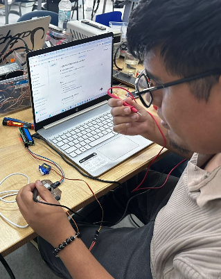
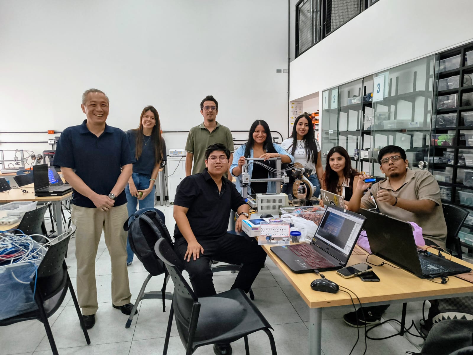
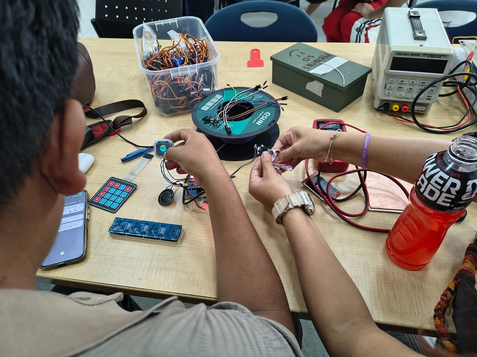
For the group assignment, we worked at the Universidad del Pacífico in Lima, where we tested and validated output devices using a PCB designed by Adrian Torres. In this case, we focused on programming and integrating a LCD I2C display and an SG90 servo motor, controlled by a XIAO RP2040.
As a team, we developed code to display information on the LCD while simultaneously controlling the servo motor’s movement. This allowed us to observe how the microcontroller sends output signals actuators and displays. ⚙️📟 to both visual and mechanical components, analyzing their behavior and response.
Through this collaborative experience, we gained a better understanding of how output devices operate in real applications, as well as how to properly control and synchronize multiple outputs within an embedded system. This was essential for strengthening our knowledge for our individual projects involving
Here is the link to learn more about the group project.
🔍 Individual Group Assignment Reflection
During the group assignment for the Output Devices week, we worked collaboratively at the Universidad del Pacífico in Lima using a PCB designed by Adrian Torres to explore how microcontrollers interact with output components. In this activity, we programmed a XIAO RP2040 to control both an LCD I2C display and an SG90 servo motor simultaneously, allowing us to observe how digital output signals are transmitted from the microcontroller to visual and mechanical devices. Through the Arduino programming process, we learned how to synchronize multiple outputs, display real-time information on the LCD screen, and generate controlled movement using the servo motor. Additionally, this experience helped me better understand power consumption behavior, signal control, and the importance of proper hardware integration when working with embedded systems that combine different types of output devices.
individual Assignment:
° Add an output device to a microcontroller board you've designed and program it to do something.
1. Introduction
In this individual assignment, I focused on working with output devices by developing a system that integrates a servo motor and an OLED display using the XIAO ESP32 S3. The objective was to understand how a microcontroller can generate both visual and mechanical outputs in response to programmed instructions.
Through this process, I programmed the OLED display to show information while simultaneously controlling the movement of the servo motor. This allowed me to explore how different output devices can be synchronized and managed within the same system.
This assignment helped me strengthen my skills in embedded programming and output control, bringing me closer to developing interactive and functional systems for my final project. ⚙️📟
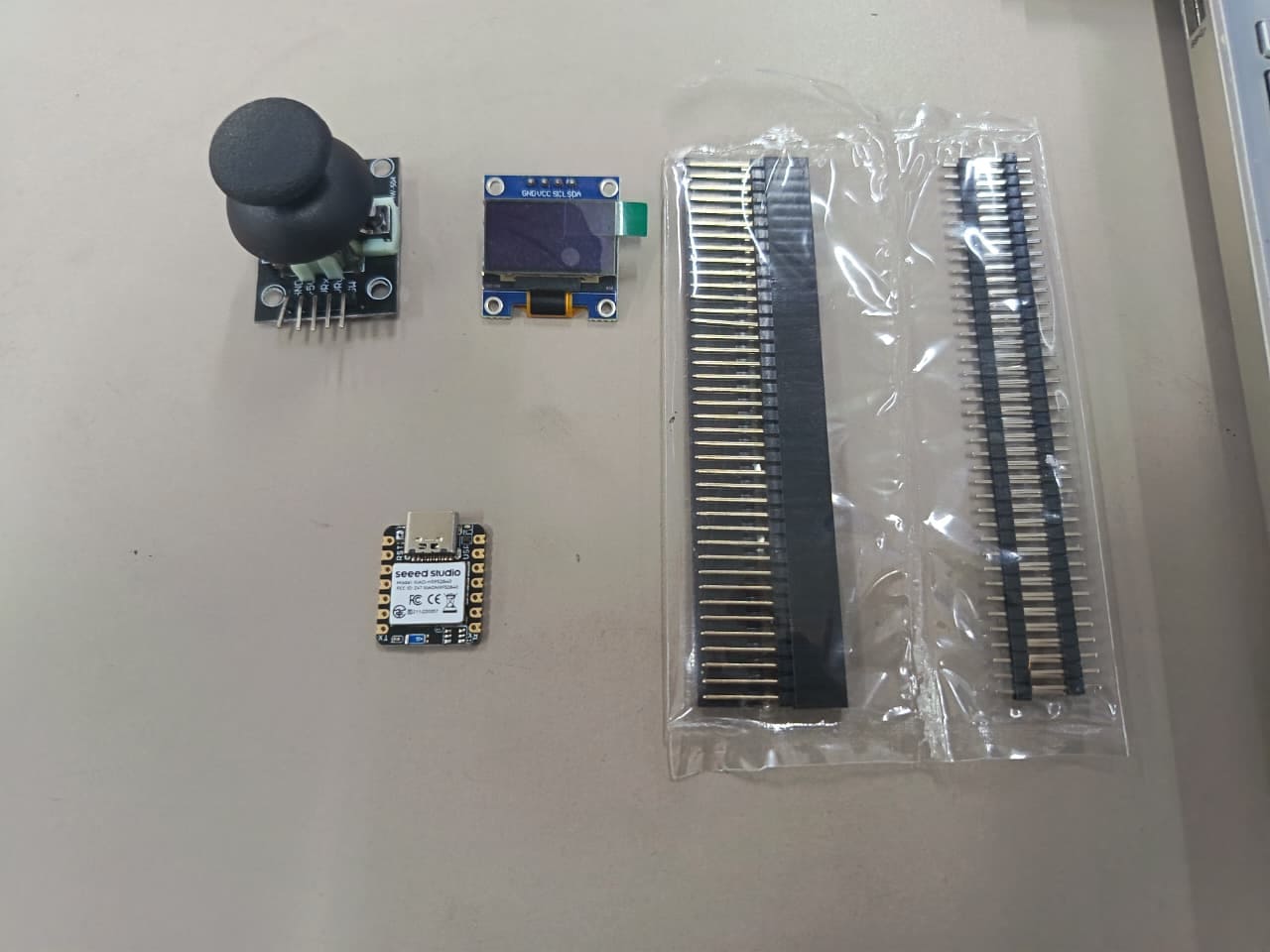
PCB Components List
The PCB was designed around the SEEED STUDIO XIAO ESP32-S3 microcontroller and includes the necessary electronic components to support output device integration. The system incorporates an OLED display for visual output and an SG90 servo motor for mechanical movement, together with connectors, power lines, and signal routing components required for communication and control. These components work together to create a functional embedded system capable of generating both graphical information and controlled motion within an embedded electronics project. ⚙️📟
| Item | Component | Amount |
|---|---|---|
| 1 | SEEED STUDIO XIAO ESP32-S3 | 1 |
| 2 | Header 01x05 P2.54 mm Horizontal SMD | 4 |
| 4 | OLED DISPLAY | 1 |
| 5 | SERVOMOTOR | 1 |
📟PCB Components
For this Output Devices assignment, I used several electronic components to build and test the functionality of my embedded system. The main controller of the project is the SEEED STUDIO XIAO ESP32-S3, which is responsible for processing the program and controlling the connected output devices. As visual output, I used a 0.96” OLED display (SSD1306) to show information and interface elements in real time. For mechanical output, I integrated an SG90 micro servo motor, allowing the system to generate controlled rotational movement through PWM signals sent by the microcontroller.⚙️📟
⚙️1. Programming Process: OLED DISPLAY
Programming Process: OLED Interface with Arduinio IDE
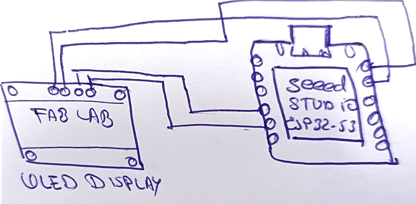
⚙️1.1 I made a Simple Sketch
I Made a Simple Sketch
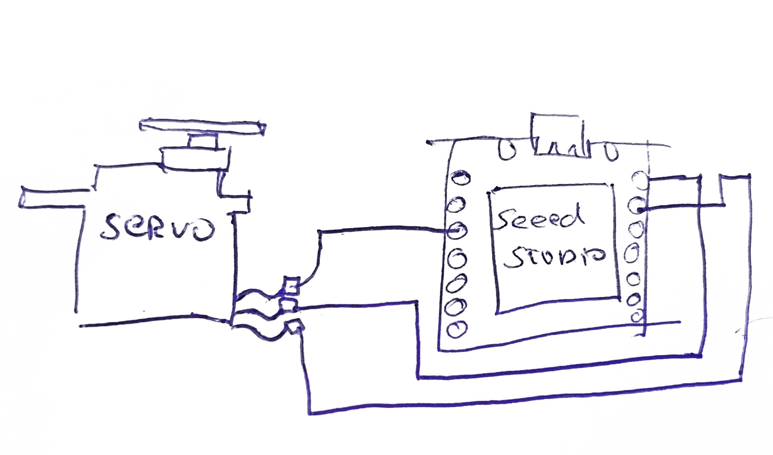
For this assignment, I created a simple hand-drawn sketch to understand the wiring connections between the Seeed Studio XIAO ESP32-S3 and the OLED display module. The sketch helped me visualize the electronic connections before assembling the real circuit and programming the board.
The drawing shows the basic I2C communication wiring required for the OLED display. Four main connections were used between the OLED display and the XIAO ESP32-S3:
- VCC: Connected to the 3.3V power pin of the XIAO ESP32-S3.
- GND: Connected to the ground pin.
- SDA: Connected to the SDA communication pin for data transfer.
- SCL: Connected to the SCL communication pin for clock synchronization.
The sketch also represents the physical arrangement of both devices and the cable routing between the OLED display and the microcontroller. This preliminary drawing made the circuit assembly process easier and reduced connection mistakes during implementation.
After completing the sketch, I programmed the ESP32-S3 using Arduino IDE and tested the OLED display by showing custom text messages on the screen. This activity helped me better understand I2C communication, circuit planning, and embedded system integration.
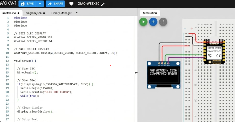
📈3. Simulation of the circuit:
The circuit simulation was developed in Wokwi to test the communication between the Seeed Studio XIAO ESP32-S3 and the OLED display before building the physical prototype. The simulation allowed verification of the wiring connections, I2C communication, and OLED functionality in a virtual environment.
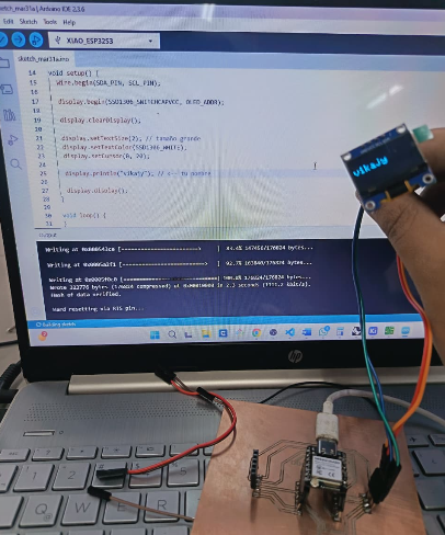
During the simulation process, the OLED display successfully showed the custom text “FAB ACADEMY 2026” and “JIANFRANCO BAZAN”. This helped confirm that the program, pin configuration, and display initialization were working correctly, reducing possible hardware connection errors during the real implementation.
⚙️4. Code visualization
The code visualization section shows the structure and organization of the Arduino program used to control the OLED display with the Seeed Studio XIAO ESP32-S3. The program includes the necessary libraries for I2C communication and OLED graphics control, as well as the configuration parameters for the display resolution and initialization.
The code also demonstrates how text messages are positioned and displayed on the OLED screen using functions such as setCursor(), println(), and display.display(). This visualization helps understand the programming flow, display initialization process, and how the ESP32-S3 communicates with the OLED module to present graphical information.
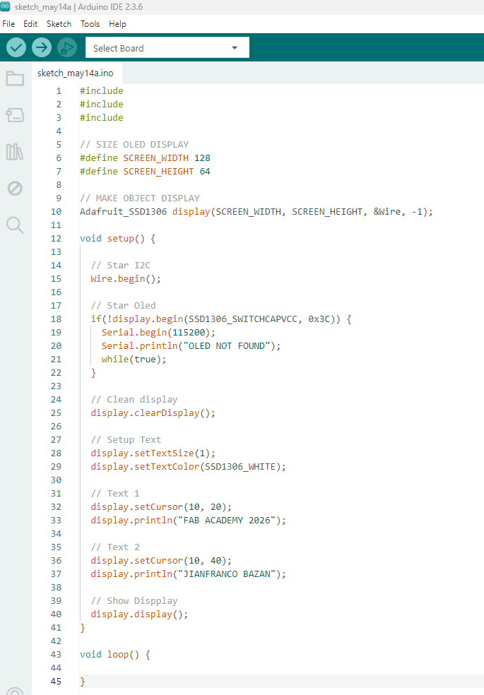
Code Writing in Arduino IDE
#include
#include
#include

// Tamaño de la pantalla OLED
#define SCREEN_WIDTH 128
#define SCREEN_HEIGHT 64

// Crear objeto display
Adafruit_SSD1306 display(SCREEN_WIDTH, SCREEN_HEIGHT, &Wire, -1);

void setup() {

  // Iniciar comunicación I2C
  Wire.begin();

  // Iniciar pantalla OLED
  if(!display.begin(SSD1306_SWITCHCAPVCC, 0x3C)) {
    Serial.begin(115200);
    Serial.println("No se encontró la pantalla OLED");
    while(true);
  }

  // Limpiar pantalla
  display.clearDisplay();

  // Configuración del texto
  display.setTextSize(1);
  display.setTextColor(SSD1306_WHITE);

  // Texto 1
  display.setCursor(10, 20);
  display.println("FAB ACADEMY 2026");

  // Texto 2
  display.setCursor(10, 40);
  display.println("JIANFRANCO BAZAN");

  // Mostrar en pantalla
  display.display();
}

void loop() {

}
Programming Process: OLED Display Text (ESP32 S3)
1.1. Libraries and Display Object
#include <Wire.h>
#include <Adafruit_GFX.h>
#include <Adafruit_SSD1306.h>

#define SCREEN_WIDTH 128
#define SCREEN_HEIGHT 64

Adafruit_SSD1306 display(SCREEN_WIDTH, SCREEN_HEIGHT, &Wire, -1);
- Wire: Enables I2C communication between the ESP32 S3 and the OLED display.
- Adafruit_GFX: Provides graphic functions for drawing text and shapes.
- Adafruit_SSD1306: Controls the OLED display module.
- SCREEN_WIDTH and SCREEN_HEIGHT: Define the OLED display resolution.
- display object: Creates the OLED display instance used in the program.
1.2. OLED Display Initialization
void setup() {

  Wire.begin();

  if(!display.begin(SSD1306_SWITCHCAPVCC, 0x3C)) {
    Serial.begin(115200);
    Serial.println("OLED not detected");
    while(true);
  }

  display.clearDisplay();
}
- Wire.begin(): Starts I2C communication.
- display.begin(): Initializes the OLED display using address 0x3C.
- display.clearDisplay(): Clears the OLED screen before showing new content.
1.3. Displaying Text on the OLED
display.setTextSize(1);
display.setTextColor(SSD1306_WHITE);

display.setCursor(10, 20);
display.println("FAB ACADEMY 2026");

display.setCursor(10, 40);
display.println("JIANFRANCO BAZAN");

display.display();
- setTextSize(1): Sets the text size displayed on the OLED.
- setTextColor(SSD1306_WHITE): Displays the text in white color.
- setCursor(x,y): Defines the text position on the screen.
- println(): Prints the message on the OLED display.
- display.display(): Updates the OLED screen with the new text.
✅Program Objective
The objective of this program is to establish communication between the ESP32 S3 and an OLED display using the I2C protocol, allowing text information to be shown on the screen. The program initializes the OLED display and presents the messages “FAB ACADEMY 2026” and “JIANFRANCO BAZAN” as a simple demonstration of text visualization using the Adafruit SSD1306 library.
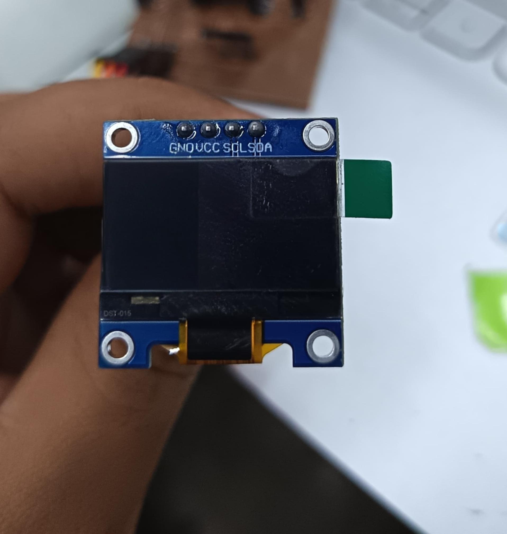
⚙️1.8. OLED display (SSD1306)
The OLED display (SSD1306) is a compact output device that uses I2C communication (SDA and SCL), making it easy to integrate with the XIAO ESP32 S3. It offers low power consumption and high contrast since each pixel emits its own light. In my project, it serves as a user interface to display real-time information such as system status, servo position, or messages like “Ready” or “Dispensing,” improving interaction and making the system more intuitive and functional. 📟⚙️
⚙️1.6 I tasted in PCB
After completing the simulation, I tested the circuit using the real PCB setup with the Seeed Studio XIAO ESP32-S3 and the OLED display module. The components were connected through the I2C communication pins, allowing the microcontroller to send data and control the display correctly.
During the PCB testing process, the OLED display successfully showed the programmed text messages, confirming that the wiring connections, power supply, and Arduino code were functioning properly. This practical test helped validate the circuit design and ensured stable communication between the ESP32-S3 and the OLED display.
⚙️2. Programming Process:Servo Motor SG90
⚙️1.1 I made a Simple Scetch
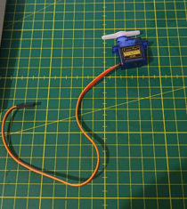
For this activity, I created a simple hand-drawn sketch to understand the wiring connections between the SG90 micro servo motor and the Seeed Studio XIAO ESP32-S3. The sketch helped me visualize the electronic setup before assembling the real circuit and programming the microcontroller.
The drawing shows the three main servo connections: VCC, GND, and Signal. The power and ground wires were connected to the corresponding power pins of the XIAO ESP32-S3, while the signal wire was connected to a GPIO pin used for PWM control. This simple sketch allowed me to better understand servo motor integration, wiring organization, and how the ESP32-S3 generates control signals to rotate the servo at different angular positions.
📈3. Simulation of the circuit:
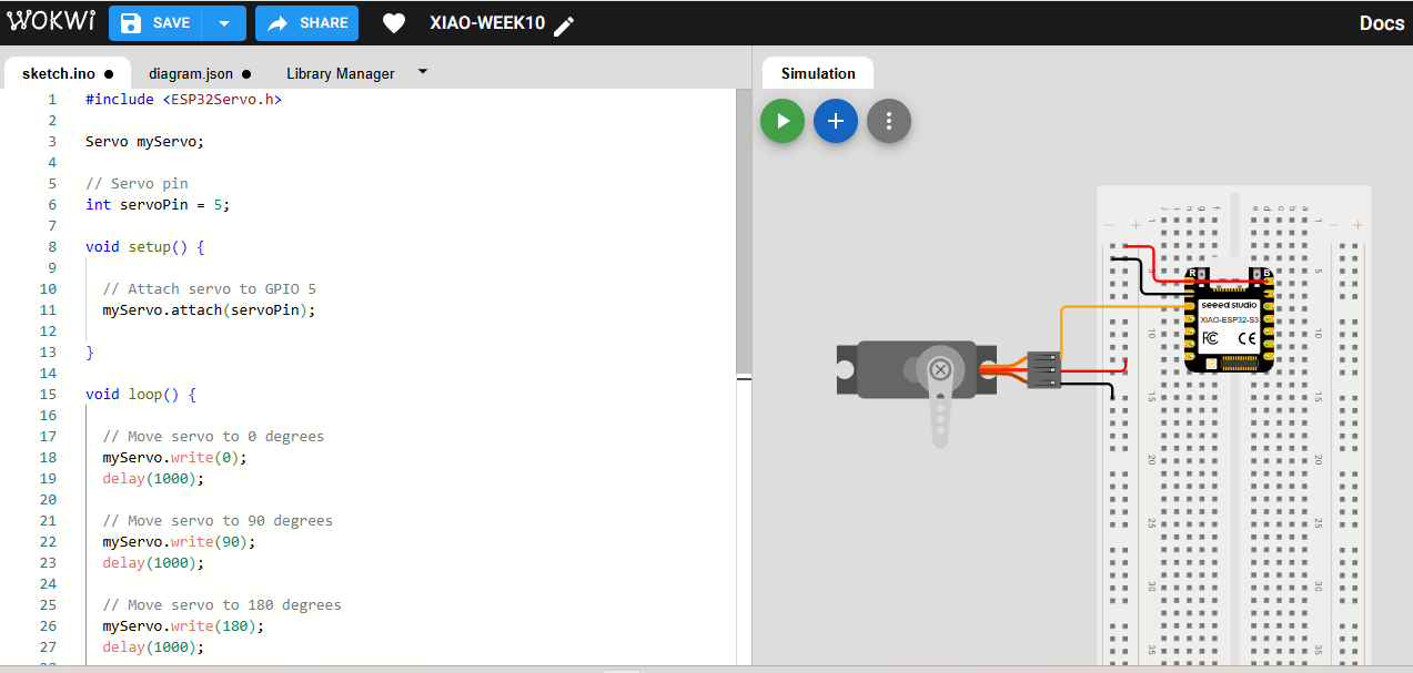
The circuit simulation was performed to verify the communication and control between the Seeed Studio XIAO ESP32-S3 and the SG90 micro servo motor before assembling the physical circuit. The simulation helped confirm the correct wiring connections and PWM signal operation required for servo movement.
During the simulation process, the servo motor successfully rotated to different angular positions programmed in the Arduino code, including 0°, 90°, and 180°. This virtual test allowed validation of the program logic, GPIO configuration, and servo response, helping reduce possible hardware errors during the real implementation.
⚙️4. Code visualization
The code visualization section presents the structure and programming flow used to control the SG90 micro servo motor with the Seeed Studio XIAO ESP32-S3. The program includes the ESP32Servo library, which allows the microcontroller to generate PWM signals required for servo motor operation.
The code demonstrates how the servo object is created, attached to a GPIO pin, and controlled using the write() function to define different angular positions. Additionally, the program uses delay intervals to control the movement timing, allowing the servo motor to rotate smoothly between 0°, 90°, and 180° positions.
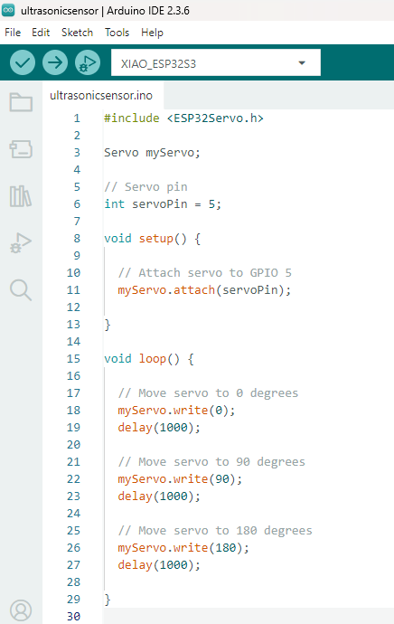
Code Writing in Arduino IDE
#include <ESP32Servo.h>

Servo myServo;

// Servo pin
int servoPin = 5;

void setup() {

  // Attach servo to GPIO 5
  myServo.attach(servoPin);

}

void loop() {

  // Move servo to 0 degrees
  myServo.write(0);
  delay(1000);

  // Move servo to 90 degrees
  myServo.write(90);
  delay(1000);

  // Move servo to 180 degrees
  myServo.write(180);
  delay(1000);

}
Programming Process: Servo SG90 Control (ESP32 S3)
1.1. Libraries and Objects
#include <ESP32Servo.h>

Servo myServo;

int servoPin = 5;
- ESP32Servo: Library used to control servo motors with the ESP32 S3.
- Servo myServo: Creates the servo motor object.
- servoPin: Defines the GPIO pin connected to the SG90 signal wire.
1.2. Servo Initialization
void setup() {

  myServo.attach(servoPin);

}
- myServo.attach(): Connects the servo motor to the selected GPIO pin.
- This initialization allows the ESP32 S3 to send PWM signals to the SG90 servo.
1.3. Servo Movement Control
void loop() {

  myServo.write(0);
  delay(1000);

  myServo.write(90);
  delay(1000);

  myServo.write(180);
  delay(1000);

}
- myServo.write(angle): Rotates the servo motor to the specified angle.
- delay(1000): Waits for 1 second before the next movement.
- The servo continuously moves between 0°, 90°, and 180° positions.
✅Program Objective
The objective of this program is to control the movement of an SG90 micro servo motor using an ESP32 S3 microcontroller. The program generates PWM signals that allow the servo to rotate to different angular positions (0°, 90°, and 180°), demonstrating basic servo motor control and position management with the ESP32Servo library.
⚙️1.9. SG90 servo motor
The SG90 servo motor is a compact actuator controlled by PWM signals, allowing precise movement between 0° and 180° using a microcontroller like the XIAO ESP32 S3. It requires simple connections (VCC, GND, and signal) and is ideal for prototyping. In my project, it is used as the main mechanism of the pill dispenser, controlling the release of doses by moving to specific angles, while working together with the OLED display to provide feedback and ensure accurate operation. ⚙️📟
⚙️ I tested in PCB
In this stage, I tested the circuit directly on the fabricated PCB using the XIAO ESP32 S3 as the main microcontroller. After assembling the components, including the OLED display and the SG90 servo motor, I powered the board and uploaded the program.
I verified the correct operation of the output devices by observing the information displayed on the OLED and the movement of the servo motor. This allowed me to confirm that the connections,. control signals, and overall system performance were working properly, ensuring proper synchronization between visual and mechanical outputs.
📟Reflection (Individual)
During this individual assignment, I learned how to program and control different output devices using the ESP32 S3 microcontroller. I worked with an OLED display and an SG90 micro servo motor, which helped me better understand how electronic components interact with a microcontroller through programming. I learned how to use libraries, configure GPIO pins, establish I2C communication, and generate PWM signals for servo control. The OLED display activity allowed me to display custom text and understand graphical visualization on embedded systems, while the servo motor activity helped me understand position control and motion management. Throughout the assignment, I also improved my skills in Arduino IDE programming, debugging, circuit connections, and documentation. This experience strengthened my knowledge of embedded systems, digital fabrication, and output device integration for future Fab Academy and mechatronics projects.
Another challenge was synchronizing both output devices in the code, making sure that the servo movement and the OLED updates worked smoothly without conflicts or delays. However, through testing and adjustments, I was able to solve these issues and achieve a stable and functional system.Files
Here are the project files available for download:
- Arduino IDE DISPLAY OLED: Download .ino
- Arduino IDE SERVOMOTOR SG90S: Download .ino