Week 11
Networking and Communications
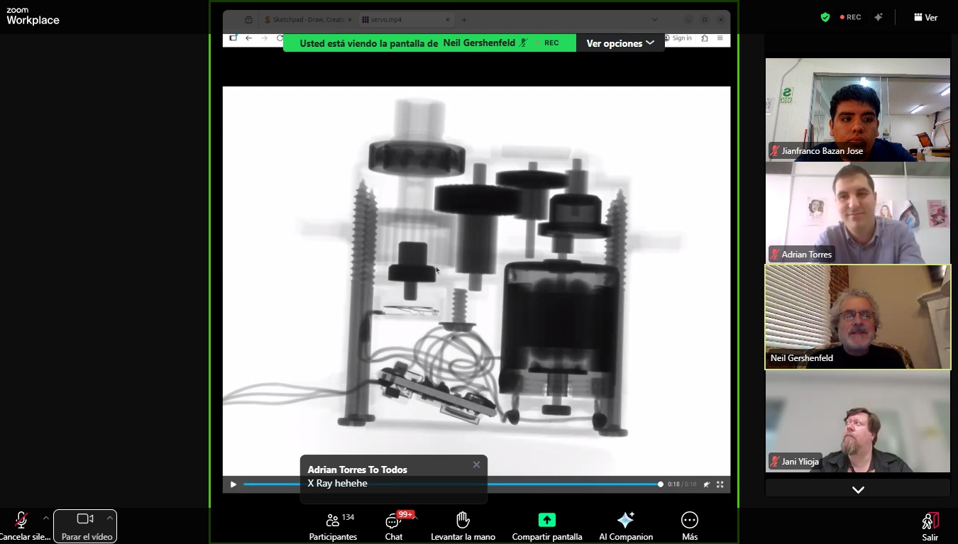
Class with Neil
During Week 11 – Networking and Communications, the main objective was to understand how different electronic systems can communicate with each other through wired or wireless connections. This involved working with microcontrollers to send and receive data, enabling interaction between multiple devices instead of operating as standalone systems.
The workflow included key stages such as selecting the communication protocol, configuring connections, programming data exchange, and testing communication between devices. Through this process, I learned how to establish reliable communication, manage data transmission, and ensure proper synchronization between systems.
This assignment helped me understand how electronic devices can share information and work collaboratively, strengthening my skills in communication protocols, programming, and embedded system integration. 🌐⚡
Group Assignment:
°Send a message between two projects
° Document your work to the group work page and reflect on your individual page what you learned
Have you answered these questions?
- I. Linked to the group assignment page. ✅
- II.Documented your project and what you have learned from implementing networking and/or communication protocols. ✅
- III.Explained the programming process(es) you used.. ✅
- IV. Ensured and documented that your addressing for boards works✅
- V. Outlined problems and how you fixed them. ✅
- VI.Included design files (or linked to where they are located if you are using a board you have designed and fabricated earlier) and original source code.✅
- VII.Included a ‘hero shot’ of your network and/or communications setup✅
Group Assignment Sumary
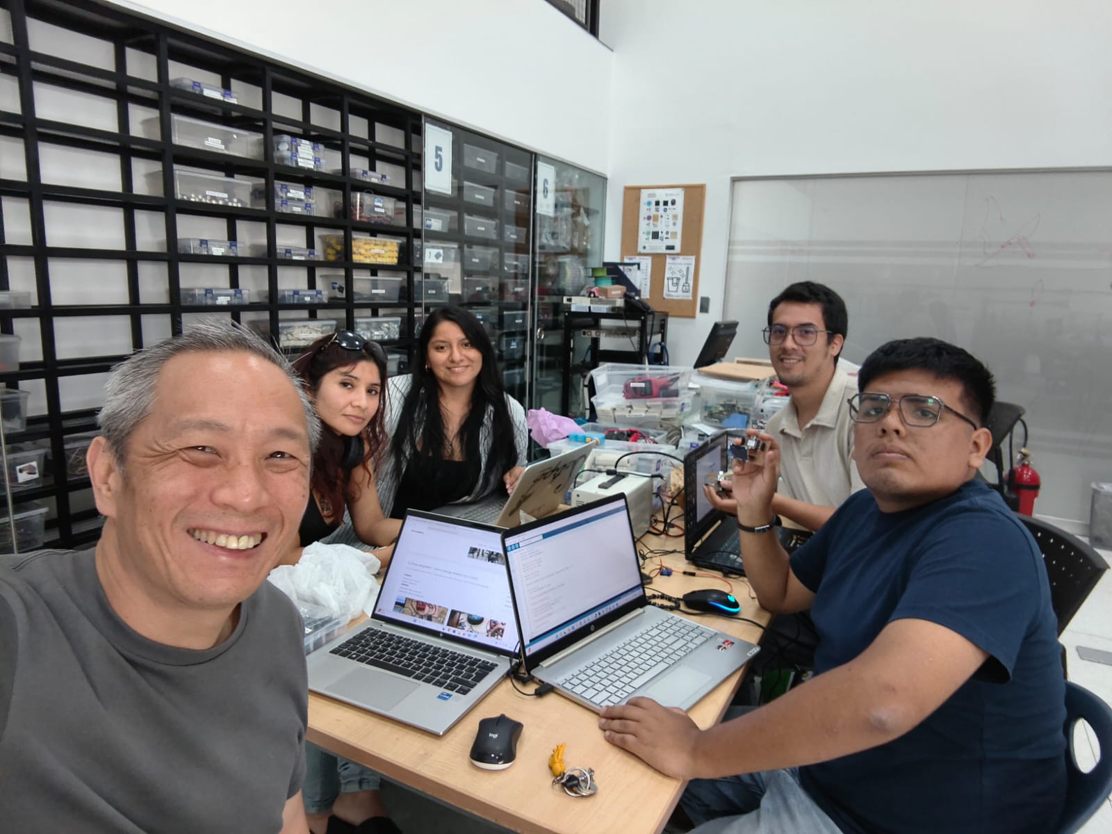
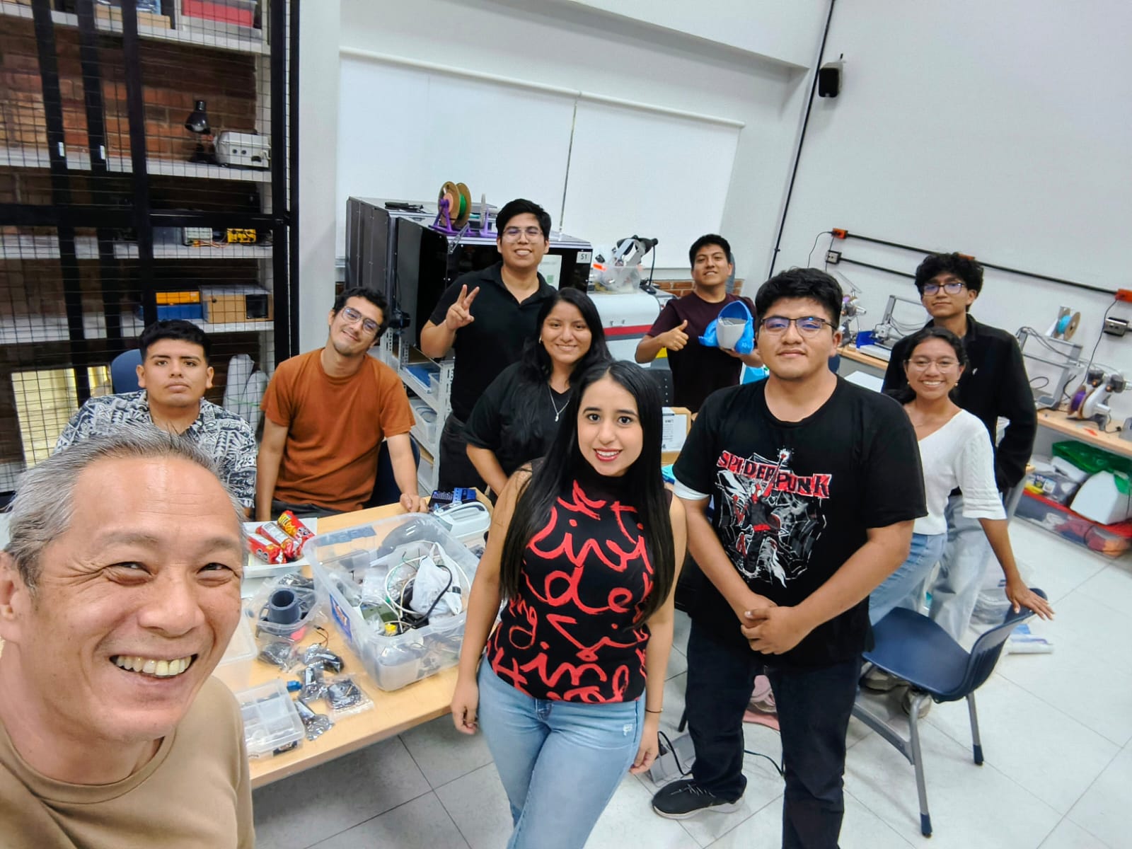
For the group assignment, we worked at Universidad del Pacífico in Lima, where we developed a networking-based system using two microcontroller boards. In this activity, we focused on establishing communication between both boards to exchange data in real time. We used MQTTX as a communication platform, creating a server connected to WiFi and enabling interaction with a XIAO ESP32 S3.
As a team, we programmed the system using Arduino IDE to send and receive data through the network. One board was connected to a pushbutton, which counted the number of presses, while the other board received this data and displayed it on a screen. This allowed us to observe how communication protocols enable synchronization between devices, where an input in one system generates a response in another.
Through this collaborative experience, we gained a deeper understanding of networking and communication in embedded systems, learning how to transmit data over WiFi, manage real-time interactions, and coordinate multiple devices working together. This knowledge is essential for developing more advanced interconnected systems for our individual projects. 🌐⚡
Here is the link to learn more about the group project.
🔍 Reflections
This assignment helped me understand how embedded systems can communicate with each other through a network instead of working independently. By using MQTTX, I was able to visualize how data is sent and received in real time, making the concept of IoT much more practical. I also learned how a simple input, like a pushbutton, can be transformed into a message and transmitted using a XIAO ESP32 S3 to generate a response on another device.
Additionally, I realized that working with communication between two systems is more complex, as it involves debugging connection issues and ensuring correct data transmission. Despite these challenges, this experience strengthened my problem-solving skills and gave me a better understanding of networking protocols. Overall, it provided a solid foundation for integrating multiple devices in future projects, especially for developing more interactive and connected systems. 🌐⚙️
individual Assignment:
° design, build and connect wired or wireless node(s) with network or bus addresses and a local input and/or output device(s)
1. Introduction
In this individual assignment, I focused on networking and communication between devices by developing a system that connects two boards through a wireless network. The objective was to understand how a microcontroller can send and receive data, enabling interaction between independent systems instead of working in isolation.
Through this process, I used MQTTX as a communication platform to transmit messages between two XIAO ESP32 S3 boards. One device was responsible for sending data based on a pushbutton input, while the other received the information and displayed it, allowing me to explore real-time data exchange and system synchronization.
This assignment helped me strengthen my understanding of communication protocols and IoT concepts, bringing me closer to developing more advanced, connected, and interactive systems for my final project. 🌐📡
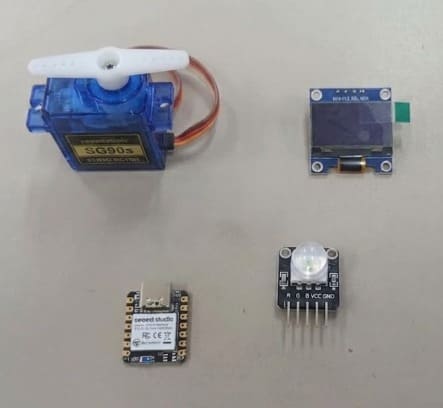
2. PCB Components List
For this assignment, I used the SEEED STUDIO XIAO ESP32-S3 as the main controller, taking advantage of its built-in WiFi capabilities to enable communication through RemoteXY. I integrated an OLED display to visualize information in real time and an RGB LED module to generate visual outputs with different colors. Additionally, the system was connected to the laboratory WiFi network, allowing remote control and interaction from a mobile device using the RemoteXY platform. This setup helped me understand how to combine wireless communication with visual output devices in an embedded system. ⚙️📡
| Item | Component | Amount |
|---|---|---|
| 1 | SEEED STUDIO XIAO ESP32-S3 | 1 |
| 2 | OLED DISPLAY (I2C) | 1 |
| 3 | RGB LED MODULE | 1 |
| 4 | Resistors (for RGB LED) | 3 |
| 5 | Header Pins / Connectors | 3 |
| 6 | WiFi Network (Laboratory) | 1 |
| 7 | RemoteXY Platform | 1 |
📟2.1 PCB Components
The PCB integrates the SEEED STUDIO XIAO ESP32-S3 as the main microcontroller, taking advantage of its built-in WiFi capabilities to enable wireless communication. It is connected to essential components such as resistors and header pins for proper interfacing and circuit stability.
In this setup, I incorporated an OLED display to provide real-time visual feedback and an RGB LED module to generate different light outputs. Additionally, the system is linked to the RemoteXY platform through the laboratory WiFi network, allowing remote control and interaction. All these components work together to create a connected electronic system capable of producing dynamic visual responses. ⚙️📡
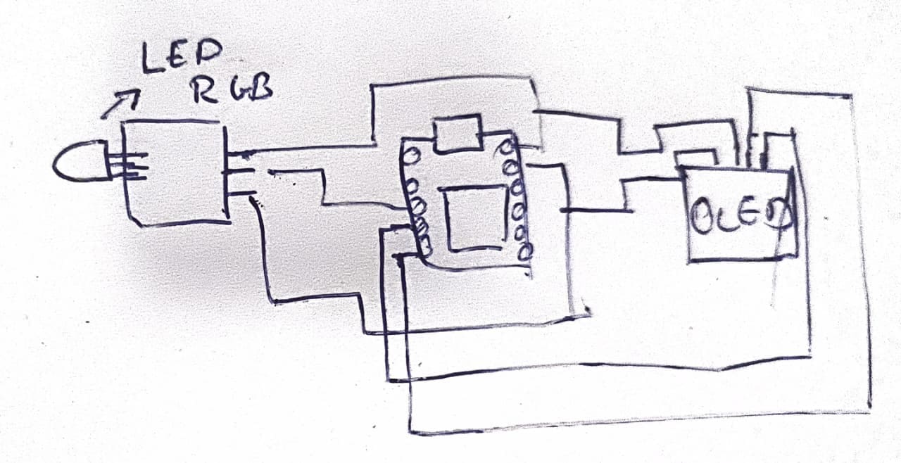
⚙️2.2 I made a Simple Scetch
In this step, I created a simple sketch to represent the connection between the XIAO ESP32 S3 and the SG90 servo motor. Based on the diagram, I defined the main wiring by connecting VCC to 5V and GND to GND, ensuring proper power supply to the servo.
For signal control, I assigned the signal pin of the servo to a GPIO pin on the microcontroller, which allows sending PWM signals to control its position. In the sketch, these connections are represented as control lines, helping to clearly understand how the ESP32 S3 sends commands to move the servo to specific angles.
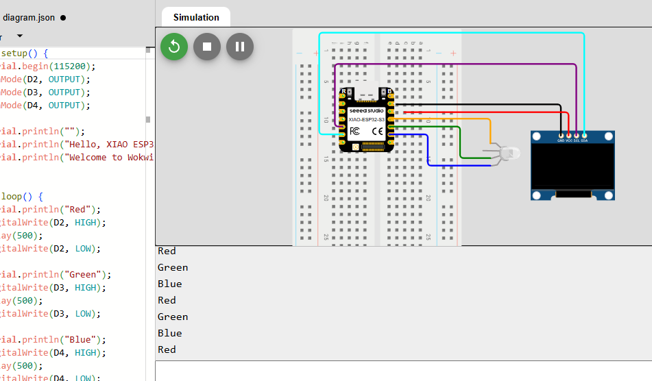
📈3 Simulation of the circuit:
In this stage, I analyzed the program used to control the OLED display and the RGB LED module with the XIAO ESP32-S3. By reviewing the code, I was able to understand how the display is initialized and updated, as well as how the RGB LED receives signals to generate different colors.
The structure of the code allowed me to clearly identify how both output devices are managed at the same time, including the functions used to display information
📈 4. Circuit + RemoteXY:
📈4.1 Wireless Communication System with the Circuit:
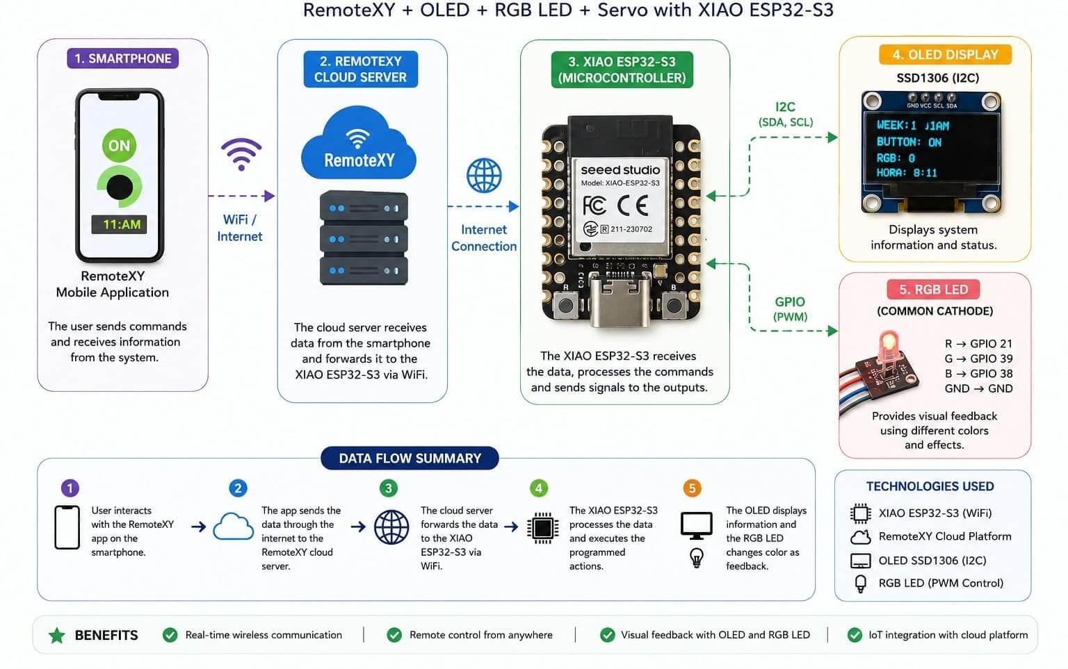
This project implements a wireless communication system using an ESP32-S3 microcontroller connected to the RemoteXY cloud platform. The main objective of this system is to allow communication between a smartphone and the electronic circuit through WiFi connectivity. The ESP32 receives commands sent from the RemoteXY mobile application and processes the information to control different output devices such as the OLED display and the RGB LED.
The communication workflow begins with the smartphone sending data through the internet to the RemoteXY cloud server. The cloud server then transfers the information wirelessly to the ESP32-S3 board. Once the ESP32 receives the data, it updates the OLED display and controls the RGB LED behavior according to the programmed logic. This communication structure demonstrates the integration of IoT technologies, embedded systems, and wireless networking within a single electronic project.
📈4.2 Setting Up the RemoteXY Wireless Interface:
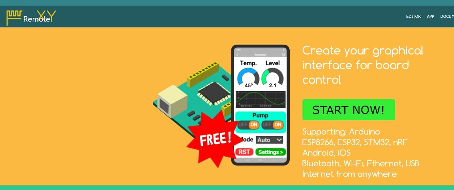
To start the development of the wireless communication system, I used the platform RemoteXY, which allows the creation of graphical interfaces for controlling microcontroller boards through Wi-Fi, Bluetooth, or Ethernet communication. As shown in the image, the platform supports different development boards such as Arduino, ESP8266, and ESP32, making it compatible with the XIAO ESP32S3 used in this project. The main objective of this step was to generate a mobile interface capable of communicating wirelessly with the board in real time.
In this stage, I accessed the RemoteXY editor and began configuring the interface elements that would later control the OLED display and RGB LED module. The platform automatically generates the communication code required for the ESP32, simplifying the process of establishing wireless networking between the smartphone and the microcontroller. This step was essential to create the wireless node requested in the assignment and to prepare the system for remote interaction and testing.
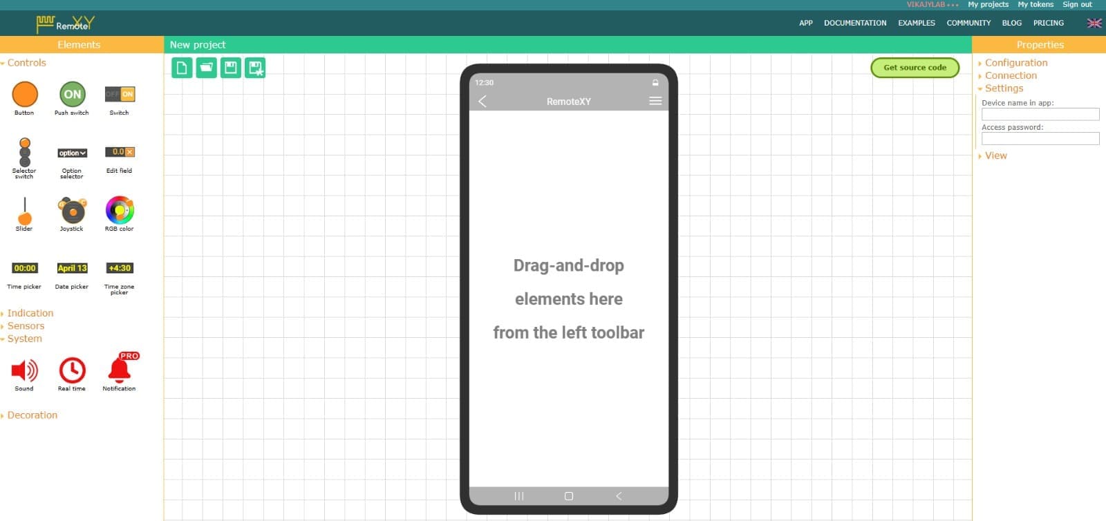
📈4.3 Creating the Mobile Interface in RemoteXY:
After creating the new project in RemoteXY, I started designing the graphical interface that would be used to control the wireless node from a smartphone. As shown in the image, the platform provides a drag-and-drop workspace where different interface elements such as buttons, sliders, RGB color selectors, switches, and sensors can be added directly into the mobile screen layout. This made it possible to customize the interface according to the needs of my project and prepare the communication between the smartphone and the XIAO ESP32S3.
In this step, I selected and organized the control elements that would interact with the OLED display and the RGB LED module connected to the ESP32 S3. The RemoteXY editor also includes configuration options for Wi-Fi connection settings and device parameters, which are necessary for establishing wireless communication. This stage was important because it defined how the user would remotely interact with the system and send commands to the microcontroller in real time.
📈4.4 Configuring the Wireless Communication Parameters:
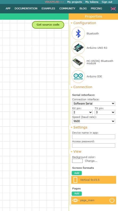
Once the interface design was prepared, the next step was configuring the communication settings in RemoteXY. As shown in the image, the platform allows the selection of the communication method, development board, and programming environment. In this project, the wireless node was configured using Bluetooth/Wi-Fi communication with the XIAO ESP32S3 and programmed through the Arduino IDE environment. The configuration panel also provided options for serial communication settings, baud rate selection, and screen format customization for the mobile application.
During this stage, I configured the connection parameters that would allow the smartphone to communicate correctly with the ESP32 S3 board. I also defined the device settings such as the application interface format and communication speed to ensure stable data transmission between the wireless node and the mobile interface. This configuration step was essential because it established the foundation for real-time communication, allowing the RGB LED and OLED display to respond to remote commands sent from the smartphone application.
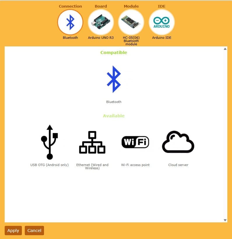
📈4.5 Selecting the Cloud Server Communication Method:
In this step, I selected the Cloud Server communication option available in RemoteXY to establish wireless connectivity between the smartphone application and the XIAO ESP32S3. As shown in the image, RemoteXY offers several communication methods such as Bluetooth, Wi-Fi Access Point, Ethernet, and Cloud Server. For this project, I chose Cloud Server because it allows remote communication through the internet without requiring the smartphone and the ESP32 board to be connected to the same local network.
By selecting the Cloud Server option, the platform automatically configured the necessary parameters for online communication between the mobile interface and the ESP32 S3 board. This method simplified the connection process and enabled real-time data exchange between the wireless node, the OLED display , and the RGB LED module. This step was important because it ensured a stable and flexible wireless communication system, fulfilling the networking requirements of the assignment while demonstrating remote device interaction through internet-based communication.
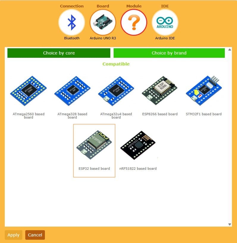
📈4.6 Selecting the ESP32 Based Board:
After configuring the communication method, the next step in RemoteXY was selecting the compatible development board for the project. As shown in the image, the platform provides support for different microcontroller families such as ATmega, ESP8266, STM32, and ESP32 boards. For this assignment, I selected the ESP32 based board option because the project was developed using the XIAO ESP32S3, which includes integrated Wi-Fi and Bluetooth capabilities required for wireless communication.
Choosing the ESP32 board profile allowed RemoteXY to generate the appropriate communication code and network configuration for the ESP32 S3 architecture. This step ensured compatibility between the hardware, the RemoteXY mobile interface, and the Arduino IDE environment used for programming. It was an important stage in the workflow because it prepared the system for stable wireless communication and enabled the interaction between the smartphone application, the OLED display, and the RGB LED module connected to the board.
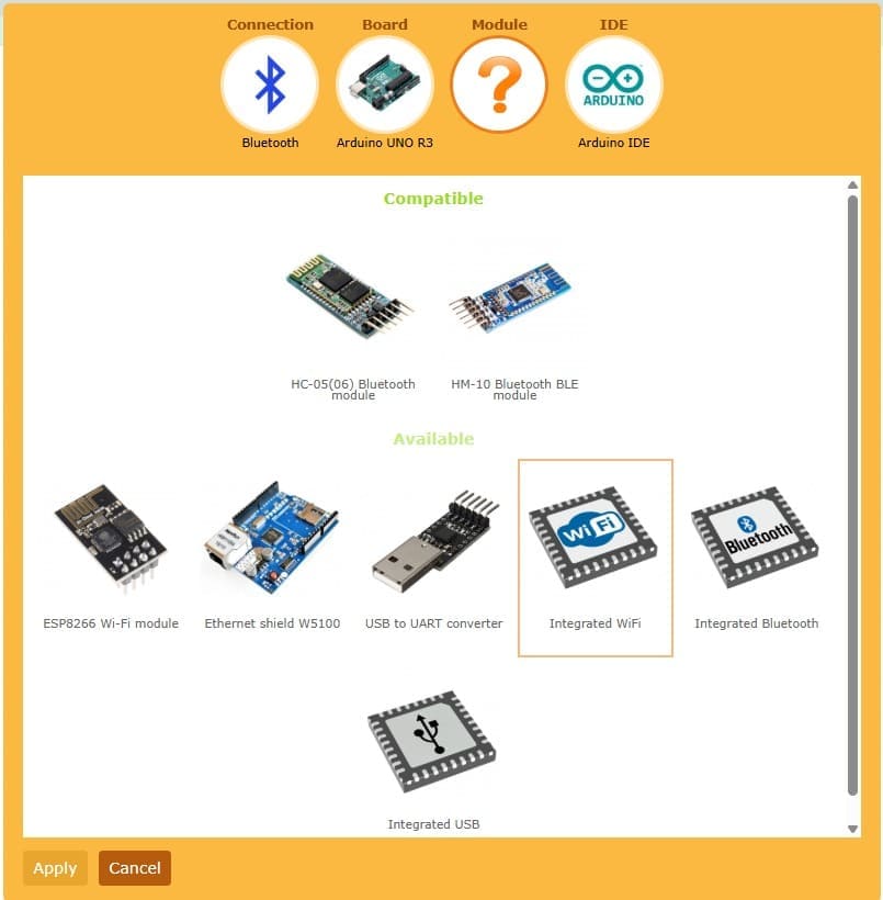
📈4.7 Configuring the Integrated Wi-Fi Module:
In the Module configuration section of RemoteXY, I selected the Integrated Wi-Fi option because the XIAO ESP32S3 already includes built-in wireless connectivity hardware. This option allows the ESP32 S3 to manage Wi-Fi communication directly without requiring an additional external communication module. By using the integrated Wi-Fi functionality, the system became more compact, efficient, and easier to configure for wireless networking applications.
This configuration step was important because it enabled direct communication between the smartphone interface and the ESP32 board through the RemoteXY Cloud Server. The integrated Wi-Fi module handled the wireless data transmission used to control the OLED display and RGB LED module in real time. Using this built-in capability simplified the hardware setup while ensuring reliable communication performance for the networking and communications assignment.
📈4.8 Selecting the Arduino IDE Environment:
In the IDE configuration section of RemoteXY, I selected the Arduino IDE option as the programming environment for the project. This option allows RemoteXY to automatically generate compatible source code that can be directly uploaded to the XIAO ESP32S3 using the Arduino development platform. The Arduino IDE was chosen because it provides a simple and efficient environment for programming ESP32-based boards and managing wireless communication libraries.
By selecting Arduino IDE, the platform generated the necessary code structure for connecting the ESP32 S3 with the RemoteXY mobile interface through Wi-Fi communication. This step simplified the programming process by integrating the network configuration, communication protocols, and interface controls into a single code file. It was an essential stage of the workflow because it prepared the project for uploading, testing, and establishing real-time communication between the smartphone, OLED display, and RGB LED module.
📈4.9 Configuring the Wi-Fi Network Connection:
In the Connections section of RemoteXY, I configured the Wi-Fi credentials that would be used by the XIAO ESP32S3 to connect to the internet. In this step, it was necessary to enter the name of the Wi-Fi network (SSID) and the corresponding password so the ESP32 S3 could establish a stable wireless connection. These credentials are later integrated into the automatically generated Arduino code used for the project.
This configuration was essential because the wireless node depends on an active internet connection to communicate with the RemoteXY Cloud Server and the smartphone application. Once connected to the selected Wi-Fi network, the ESP32 S3 was able to send and receive real-time data, allowing remote interaction with the OLED display and RGB LED module. This step ensured proper networking functionality and enabled reliable wireless communication throughout the assignment.
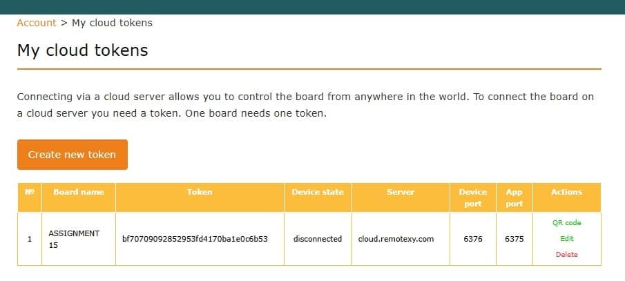
📈4.10 Creating the Cloud Token for Remote Communication
In the My Cloud Tokens section of RemoteXY, I created a new cloud token that would be used to establish communication between the smartphone application and the XIAO ESP32S3 through the RemoteXY Cloud Server. For this project, I created a token named Assignment11JIAN, which serves as a unique identifier for the wireless communication session and links the ESP32 S3 board to the mobile interface.
This token was later integrated into the Arduino code generated by RemoteXY, allowing secure and reliable communication over the internet. The cloud token plays an important role because it authenticates the connection between devices and ensures that the smartphone application communicates with the correct ESP32 project. This step completed the cloud communication setup and prepared the system for real-time remote control of the OLED display and RGB LED module.
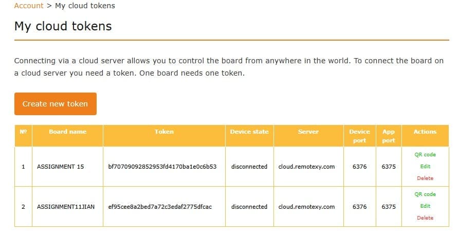
📈4.11 Creating the Cloud Token for Remote Communication
In the My Cloud Tokens section of RemoteXY, I created a new cloud token that would be used to establish communication between the smartphone application and the XIAO ESP32S3 through the RemoteXY Cloud Server. For this project, I created a token named Assignment11JIAN, which serves as a unique identifier for the wireless communication session and links the ESP32 S3 board to the mobile interface.
This token was later integrated into the Arduino code generated by RemoteXY, allowing secure and reliable communication over the internet. The cloud token plays an important role because it authenticates the connection between devices and ensures that the smartphone application communicates with the correct ESP32 project. This step completed the cloud communication setup and prepared the system for real-time remote control of the OLED display and RGB LED module.
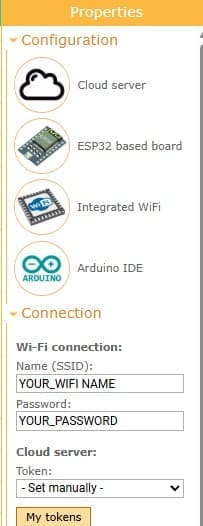
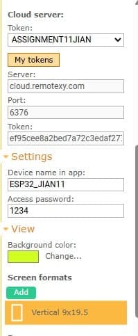
📈4.12 Verifying the Cloud Server Configuration
After creating the cloud token in RemoteXY, I reviewed the Cloud Server section to verify that the communication parameters were automatically generated. At this stage, the fields for Server, Port, and Token were already filled with the information associated with the previously created token Assignment11JIAN. These parameters are essential because they define the connection settings that allow the XIAO ESP32S3 to communicate with the RemoteXY Cloud Server.
This step confirmed that the cloud communication system was correctly configured and ready to establish wireless networking between the smartphone application and the ESP32 S3 board. The automatically generated server information simplified the setup process and reduced the possibility of manual configuration errors. With these parameters properly configured, the project was prepared for real-time remote communication and interaction with the OLED display and RGB LED module.
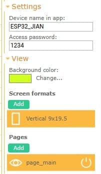
📈4.13 Configuring the Application Settings
In the Settings section of RemoteXY, I configured the parameters related to the mobile application connection. In this step, I filled in the Device Name in App, which defines how the project will appear inside the RemoteXY mobile application, and the Access Password, which provides an additional level of security for accessing the wireless node. These settings help identify and protect the communication between the smartphone and the XIAO ESP32S3.
This configuration step was important because it personalized the wireless communication system and ensured that only authorized users could connect to the project through the mobile application. Once these parameters were completed, the ESP32 S3 was ready to be recognized inside the RemoteXY app and establish secure communication with the OLED display and RGB LED module. This stage finalized the main connection settings before generating and uploading the Arduino code.
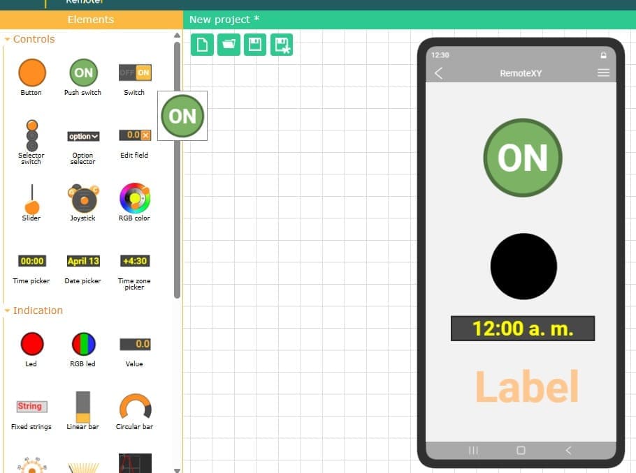
📈4.14 Designing the Interactive Mobile Interface
After completing the connection and configuration settings in RemoteXY, I started designing the interactive mobile interface that would control and display information from the wireless node. As shown in the image, I added different graphical elements from the Controls and Indication panels, including a push switch button, LED indicators, labels, and display components. These interface elements allow the user to send commands from the smartphone and visualize the system status in real time through the application connected to the XIAO ESP32S3.
This stage was important because it defined how the user would interact with the project remotely. The ON/OFF control was used to activate specific functions of the ESP32 S3, while the visual indicators and labels provided feedback from the system, including information displayed on the OLED screen and RGB LED module. By organizing the interface elements inside the mobile layout, I created a more intuitive and user-friendly wireless control system that fulfilled the networking and communication requirements of the assignment.
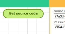
📈4.15 Generating the Source Code
After completing the interface design and communication settings in RemoteXY, the next step was selecting the Get Source Code option. This function automatically generated the Arduino code required for the project, including the wireless communication parameters, cloud server configuration, interface controls, and connection settings for the XIAO ESP32S3. The generated code also included the necessary RemoteXY libraries and predefined variables linked to the graphical interface elements created in the editor.
This step was essential because it simplified the programming workflow and ensured compatibility between the mobile application and the ESP32 S3 board. By automatically generating the source code, RemoteXY reduced manual coding errors and provided a ready-to-use communication structure for the wireless node. The code was later copied into the Arduino IDE, where additional programming for the OLED display and RGB LED module was integrated before uploading the project to the board.
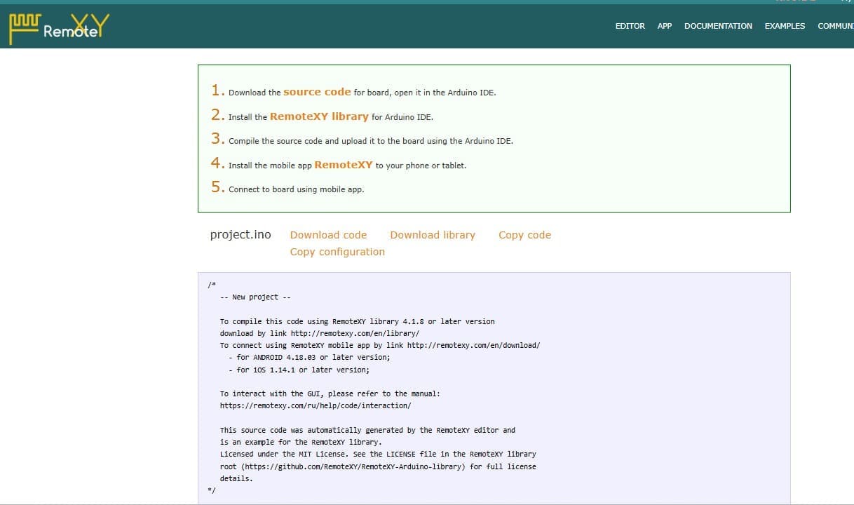
📈4.16 Downloading and Preparing the Arduino Source Code
After selecting the Get Source Code option in RemoteXY, the platform generated the complete Arduino project file required for the wireless communication system. As shown in the image, RemoteXY provided several options such as Download code, Download library, Copy code, and Copy configuration. In this step, I downloaded the generated source code and prepared it to be opened in the Arduino IDE for programming the XIAO ESP32S3.
The generated instructions also indicated the need to install the RemoteXY library before compiling the code. Once the library was installed, the source code could be compiled and uploaded directly to the ESP32 S3 board through the Arduino IDE. This step was important because it connected the graphical mobile interface created in RemoteXY with the physical hardware components, including the OLED display and RGB LED module, enabling real-time wireless communication and remote interaction.
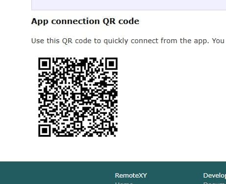
📈4.17 Connecting the Mobile Application Using the QR Code
After generating and uploading the Arduino source code, RemoteXY provided an App Connection QR Code that allows quick access to the wireless project from the mobile application. This QR code contains the connection information required for the smartphone to communicate directly with the XIAO ESP32S3 through the configured Cloud Server settings. By scanning the QR code with the RemoteXY mobile app, the connection process becomes faster and easier without manually entering the server parameters.
This step was important because it simplified the setup of the mobile interface and ensured a correct connection between the smartphone and the ESP32 S3 wireless node. Once the QR code was scanned, the application automatically loaded the custom interface created for the project, allowing real-time interaction with the OLED display and RGB LED module. This feature improved usability and demonstrated an efficient wireless communication workflow for the assignment.
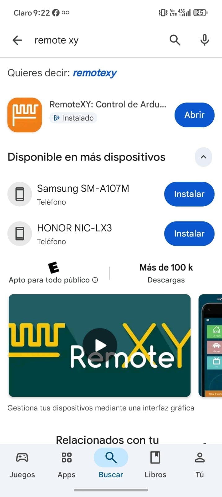
📈4.18 Installing the RemoteXY Mobile Application
To establish communication between the smartphone and the wireless node, I installed the RemoteXY Mobile App on my mobile device through the Google Play Store(You can dowload it in APP STORE if you want). As shown in the image, the application allows direct interaction with Arduino and ESP32-based projects created in RemoteXY. This app is essential because it provides the graphical interface used to control and monitor the XIAO ESP32S3 remotely.
After installing the application, I used it to scan the generated QR connection code and automatically load the custom interface designed for the project. This enabled real-time wireless communication between the smartphone, the OLED display, and the RGB LED module connected to the ESP32 S3 board. Installing the app completed the setup process and allowed the project to be tested and controlled directly from the mobile device.
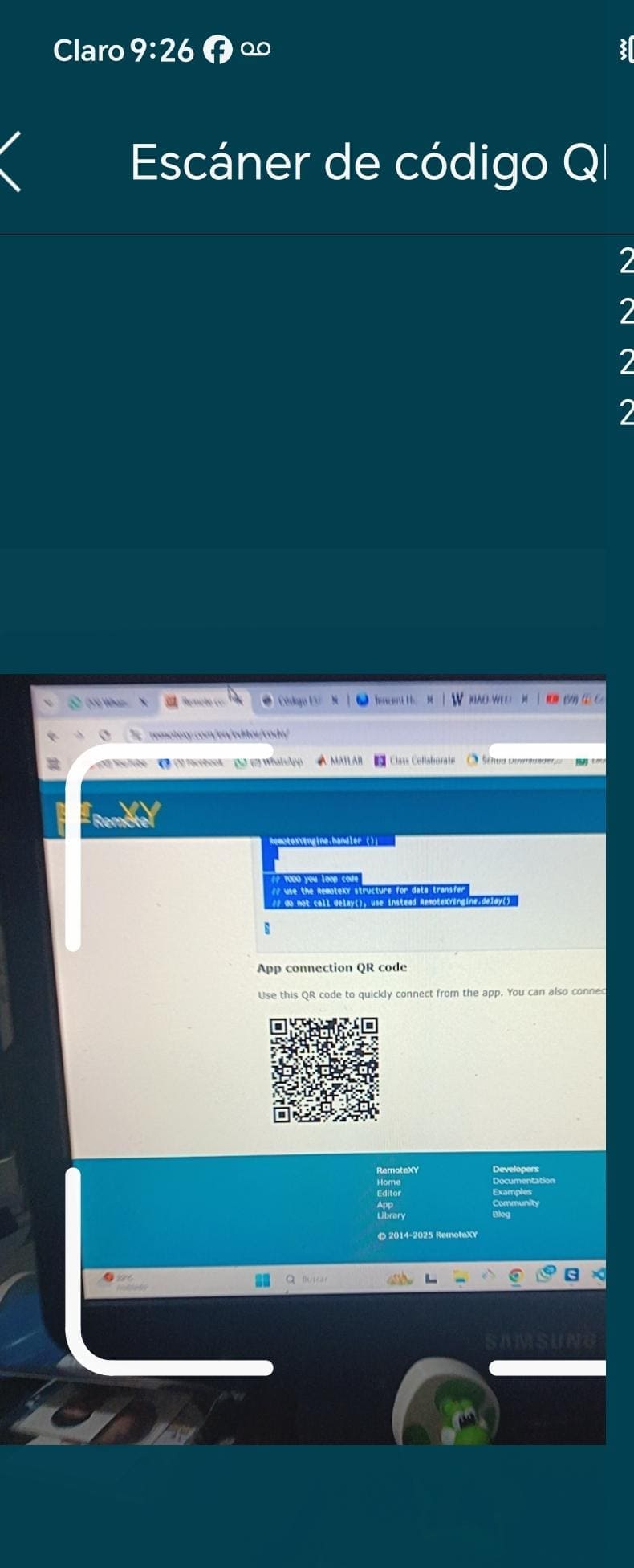
📈4.19 Scanning the QR Code for App Connection
To connect the mobile application with the wireless project, I used the QR code scanning feature available in the RemoteXY Mobile App. As shown in the image, the smartphone camera was used to scan the QR code generated by the RemoteXY platform. This QR code contains all the necessary cloud connection information, allowing the application to automatically recognize and connect to the XIAO ESP32S3 without manually entering server details.
This step simplified the connection process and ensured that the mobile interface was correctly linked to the wireless node through the Cloud Server configuration. Once the QR code was scanned successfully, the application automatically loaded the custom graphical interface created for the project, enabling real-time communication and remote interaction with the OLED display and RGB LED module. This confirmed that the wireless networking system was functioning properly and ready for testing.
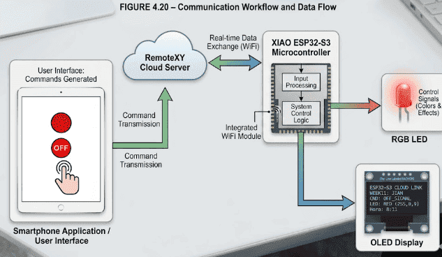
📈4.20 Communication Workflow and Data Flow
The communication system operates by continuously exchanging data between the smartphone application and the ESP32-S3 microcontroller through the RemoteXY cloud server. The smartphone acts as the user interface, where different commands and controls are generated. These commands travel through the cloud server and are received by the ESP32 using the integrated WiFi module.
After processing the received information, the ESP32 updates the OLED display with messages or system information while simultaneously controlling the RGB LED colors and effects. This real-time communication process allows the system to respond immediately to user actions, demonstrating how cloud-based IoT communication can be integrated into embedded electronic systems..
⚙️ 5. Code visualization
In this stage, I analyzed the program used to control the OLED display, the RGB LED module, and the servo motor using the XIAO ESP32-S3 with RemoteXY over a WiFi connection. By reviewing the code, I understood how the system establishes communication with the RemoteXY cloud server, allowing real- time control from a mobile interface. Additionally, I identified how the OLED display is initialized through I2C communication and continuously updated to show system status, including button state, RGB mode, and time data received from the interface.
The structure of the code also allowed me to understand how multiple output devices are managed simultaneously. The RGB LED is controlled using predefined color states that change each time the button is activated, while the servo motor responds to the same input by switching between positions This helped me verify pin configurations, signal control using PWM, and the synchronization between wireless commands, visual outputs on the OLED, and physical responses from the servo motor. ⚙️📡
⚙️ 6. Programming Process-Smart Output System with OLED Display and Servo Control
Programming Process: Potentiometer Reading with Arduinio IDE
Once in the directory, I open the new script files marked in a green box, using the Rhinoceros program.
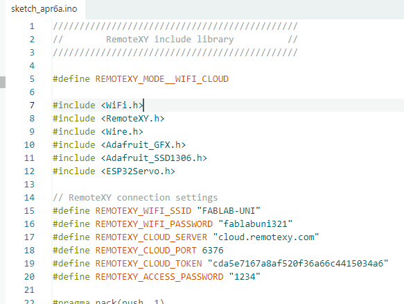
7.Code Writing in Arduino IDE
//////////////////////////////////////////////
// RemoteXY include library //
//////////////////////////////////////////////
#define REMOTEXY_MODE__WIFI_CLOUD
#include
#include
#include
#include
#include
#include
// RemoteXY connection settings
#define REMOTEXY_WIFI_SSID "WI_FI"
#define REMOTEXY_WIFI_PASSWORD "YOURPASSWORD"
#define REMOTEXY_CLOUD_SERVER "cloud.remotexy.com"
#define REMOTEXY_CLOUD_PORT 6376
#define REMOTEXY_CLOUD_TOKEN "cda5e7167a8af520f36a66c4415034a6"
#define REMOTEXY_ACCESS_PASSWORD "1234"
#pragma pack(push, 1)
uint8_t const PROGMEM RemoteXY_CONF_PROGMEM[] = {
255,3,0,3,0,71,0,19,0,0,0,88,73,65,79,69,83,80,51,50,
74,73,65,78,0,31,1,106,200,1,1,4,0,10,27,11,46,46,48,4,
26,31,79,78,0,31,79,70,70,0,65,33,68,39,39,112,13,8,119,93,
20,77,6,94,26,129,13,151,83,34,64,17,76,97,98,101,108,0 };
struct {
uint8_t pushSwitch_01;
uint8_t editTime_01_hour;
uint8_t editTime_01_minute;
uint8_t led_01_r;
uint8_t led_01_g;
uint8_t led_01_b;
uint8_t connect_flag;
} RemoteXY;
#pragma pack(pop)
/////////////////////////////////////////////
// OLED CONFIG //
/////////////////////////////////////////////
#define SCREEN_WIDTH 128
#define SCREEN_HEIGHT 64
#define OLED_ADDR 0x3C
#define SDA_PIN D4
#define SCL_PIN D5
Adafruit_SSD1306 display(SCREEN_WIDTH, SCREEN_HEIGHT, &Wire, -1);
/////////////////////////////////////////////
// PIN //
/////////////////////////////////////////////
#define PIN_R D3
#define PIN_G D2
#define PIN_B D1
#define PIN_SERVO D7
Servo miServo;
/////////////////////////////////////////////
// SETUP //
/////////////////////////////////////////////
void setup()
{
RemoteXY_Init ();
// RGB
pinMode(PIN_R, OUTPUT);
pinMode(PIN_G, OUTPUT);
pinMode(PIN_B, OUTPUT);
// Servo
miServo.attach(PIN_SERVO);
// OLED
Wire.begin(SDA_PIN, SCL_PIN);
display.begin(SSD1306_SWITCHCAPVCC, OLED_ADDR);
display.clearDisplay();
display.setTextSize(1);
display.setTextColor(WHITE);
display.setCursor(0, 0);
display.println("Sistema iniciado");
display.display();
}
/////////////////////////////////////////////
// LOOP //
/////////////////////////////////////////////
void loop()
{
RemoteXY_Handler ();
// ====== NEW LOGIC RGB ======
static uint8_t lastState = 0;
static int colorIndex = 0;
// Detectar cambio OFF -> ON
if (RemoteXY.pushSwitch_01 == 1 && lastState == 0) {
colorIndex++;
if (colorIndex > 5) colorIndex = 0;
}
lastState = RemoteXY.pushSwitch_01;
// CONTROL RGB
if (RemoteXY.pushSwitch_01 == 1) {
switch (colorIndex) {
case 0: // RED
analogWrite(PIN_R, 255);
analogWrite(PIN_G, 0);
analogWrite(PIN_B, 0);
break;
case 1: // GREEN
analogWrite(PIN_R, 0);
analogWrite(PIN_G, 255);
analogWrite(PIN_B, 0);
break;
case 2: // BLUE
analogWrite(PIN_R, 0);
analogWrite(PIN_G, 0);
analogWrite(PIN_B, 255);
break;
case 3: // YELLOW
analogWrite(PIN_R, 255);
analogWrite(PIN_G, 255);
analogWrite(PIN_B, 0);
break;
case 4: // Morado
analogWrite(PIN_R, 255);
analogWrite(PIN_G, 0);
analogWrite(PIN_B, 255);
break;
case 5: // Cyan
analogWrite(PIN_R, 0);
analogWrite(PIN_G, 255);
analogWrite(PIN_B, 255);
break;
}
} else {
// turn off RGB
analogWrite(PIN_R, 0);
analogWrite(PIN_G, 0);
analogWrite(PIN_B, 0);
}
// 🎮 CONTROL SERVO
if (RemoteXY.pushSwitch_01 == 1) {
miServo.write(90);
} else {
miServo.write(0);
}
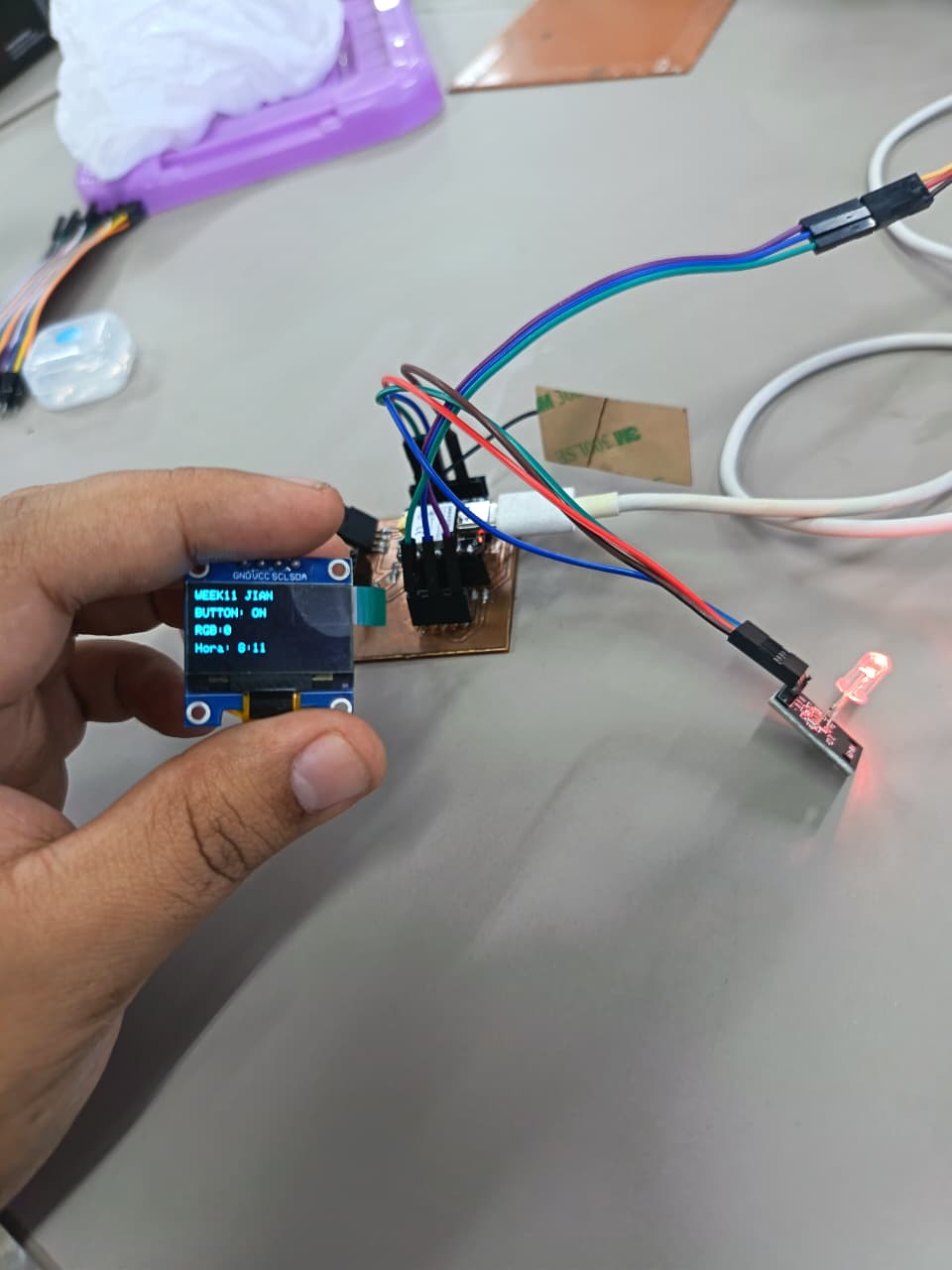
// 🖥️ OLED
display.clearDisplay();
display.setCursor(0,0);
display.println("WEEK11 JIAN");
display.setCursor(0,15);
display.print("BUTTON: ");
display.println(RemoteXY.pushSwitch_01 ? "ON" : "OFF");
display.setCursor(0,30);
display.print("RGB:");
display.print(colorIndex);
display.println("");
display.setCursor(0,45);
display.print("Hora: ");
display.print(RemoteXY.editTime_01_hour);
display.print(":");
display.println(RemoteXY.editTime_01_minute);
display.display();
RemoteXY_delay(100);
}
Programming Process: RemoteXY + OLED + RGB + Servo (ESP32-S3)
7.1. Libraries and Configuration
#include <WiFi.h>
#include <RemoteXY.h>
#include <Wire.h>
#include <Adafruit_GFX.h>
#include <Adafruit_SSD1306.h>
#include <ESP32Servo.h>

#define SCREEN_WIDTH 128
#define SCREEN_HEIGHT 64

#define PIN_R D3
#define PIN_G D2
#define PIN_B D1
#define PIN_SERVO D7

Adafruit_SSD1306 display(SCREEN_WIDTH, SCREEN_HEIGHT, &Wire, -1);
Servo miServo;
- WiFi & RemoteXY: Enable wireless communication and remote control. 🌐
- Wire: Enables I2C communication for the OLED.
- Adafruit_SSD1306: Controls the OLED display.
- ESP32Servo: Controls the servo motor using PWM.
- RGB Pins: Define outputs for color control.
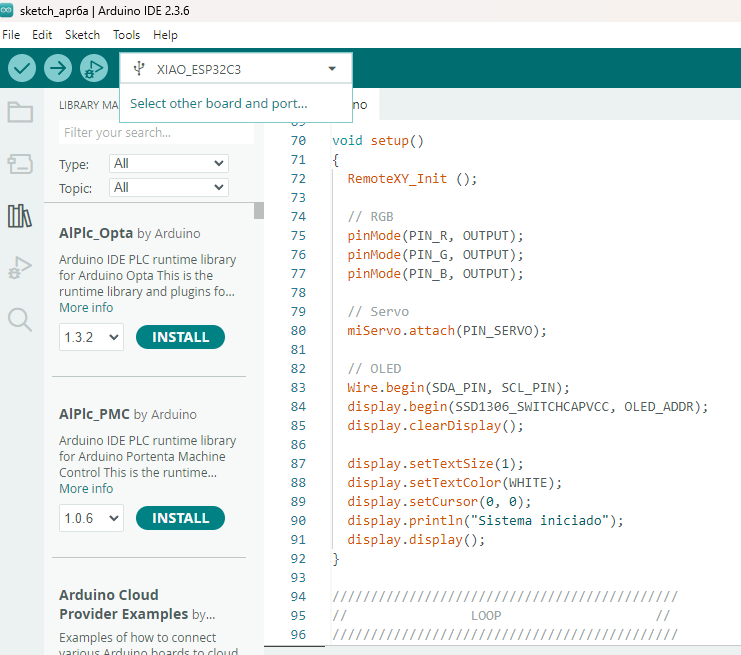
7.2. Setup Configuration
void setup()
{
  RemoteXY_Init();

  pinMode(PIN_R, OUTPUT);
  pinMode(PIN_G, OUTPUT);
  pinMode(PIN_B, OUTPUT);

  miServo.attach(PIN_SERVO);

  Wire.begin(D4, D5);
  display.begin(SSD1306_SWITCHCAPVCC, 0x3C);

  display.clearDisplay();
  display.setTextSize(1);
  display.setTextColor(WHITE);

  display.setCursor(0,0);
  display.println("Sistema iniciado");
  display.display();
}
- Initializes RemoteXY connection via WiFi.
- Configures RGB pins and attaches the servo motor.
- Initializes OLED display using I2C communication.
- Displays initial system status.
7.3. Remote Control Logic
RemoteXY_Handler();

if (RemoteXY.pushSwitch_01 == 1) {
  miServo.write(90);
} else {
  miServo.write(0);
}
- Receives commands from RemoteXY interface.
- Controls servo position based on button state.
7.4. RGB Color Control
if (RemoteXY.pushSwitch_01 == 1) {
  analogWrite(PIN_R, 255);
  analogWrite(PIN_G, 0);
  analogWrite(PIN_B, 0);
} else {
  analogWrite(PIN_R, 0);
  analogWrite(PIN_G, 0);
  analogWrite(PIN_B, 0);
}
- Controls RGB LED using PWM signals.
- Activates colors when the button is ON and turns off when OFF. 🌈
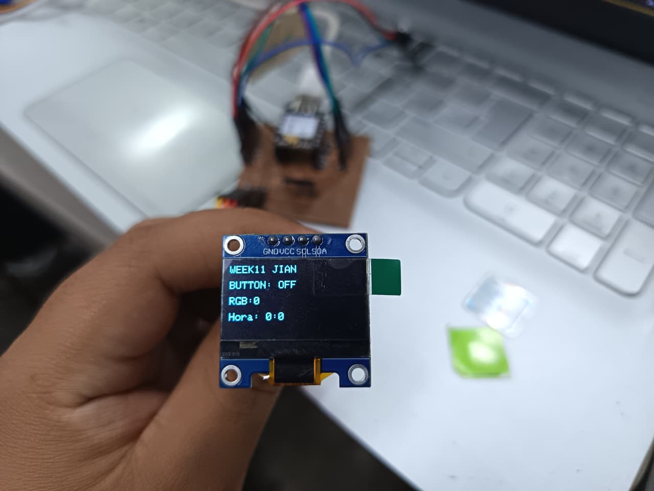
7.5. OLED Display Update
display.clearDisplay();

display.setCursor(0,0);
display.println("WEEK11 JIAN");

display.setCursor(0,15);
display.print("BUTTON: ");
display.println(RemoteXY.pushSwitch_01 ? "ON" : "OFF");

display.display();
- Updates OLED screen with real-time system status.
- Displays button state received from RemoteXY. 🖥️
7.6. Loop Execution
RemoteXY_delay(100);
- Maintains stable communication with RemoteXY.
- Ensures smooth synchronization between devices.
✅7.7 Program Objective
Control an RGB LED module and a servo motor through a wireless interface using RemoteXY, while displaying real-time system information on an OLED screen. This demonstrates the integration of wireless communication with both visual and mechanical outputs in an embedded system. ⚙️📡
⚙️ 8. OLED display (SSD1306)
The OLED display (SSD1306) is a compact output device that uses I2C communication (SDA and SCL), making it easy to integrate with the XIAO ESP32 S3. It offers low power consumption and high contrast since each pixel emits its own light. In my project, it serves as a user interface to display real-time information such as system status, servo position, or messages like “Ready” or “Dispensing,” improving interaction and making the system more intuitive and functional. 📟⚙️
⚙️9.1 Troubleshooting and Debugging Process
During the implementation of the networking system, several communication problems appeared between the ESP32-S3 board and the RemoteXY cloud platform. One of the first issues was related to unstable WiFi connectivity caused by incorrect SSID credentials and weak wireless signal strength. This prevented the ESP32 from establishing a stable connection with the cloud server. The problem was solved by verifying the WiFi credentials inside the Arduino IDE code and testing the system closer to the wireless router.
Another issue occurred when the OLED display did not update correctly after receiving data from the RemoteXY application. After monitoring the Serial Monitor output, it was discovered that the OLED initialization sequence and communication timing were incorrect. The issue was fixed by reorganizing the setup configuration, adding proper delays, and verifying the OLED I2C address. Additional debugging tests were also performed to ensure that the RGB LED responded correctly to the commands sent from the smartphone application.
⚙️9.2 PCB Testing and Validation
Several tests were performed to validate the communication and functionality of the complete system. The ESP32-S3 was connected to the RemoteXY cloud platform while monitoring the serial communication through the Arduino IDE Serial Monitor. Different commands were sent from the smartphone application to verify that the OLED display updated correctly and that the RGB LED changed colors according to the programmed conditions.
The testing process also included verifying WiFi reconnection stability, response time, and synchronization between all connected devices. Through these experiments, the system demonstrated stable wireless communication between the smartphone, cloud server, ESP32-S3, OLED display, and RGB LED. These validation tests confirmed that the networking architecture and embedded system integration were functioning correctly.⚙️📟
📟 10. Individual Reflection
This week’s Networking and Communications assignment allowed me to better understand how wireless communication systems can be integrated into embedded electronics projects using ESP32 technology. By working with the XIAO ESP32S3 and the RemoteXY platform, I learned how to configure cloud-based communication, create a custom mobile interface, and establish real-time interaction between a smartphone and hardware components such as an OLED display and an RGB LED module. One of the most valuable parts of this assignment was learning how wireless nodes communicate through internet-based services instead of only local connections.
During the development process, I also improved my understanding of ESP32 networking configuration, Arduino IDE integration, and the importance of organizing communication parameters correctly for stable connectivity. Using RemoteXY simplified many programming tasks, but it also helped me understand how communication protocols, cloud tokens, and Wi-Fi credentials work together in a real embedded system. This assignment gave me practical experience in creating interactive IoT-style applications and showed me how wireless communication can be applied to future digital fabrication and smart device projects.
Files
Here are the project files available for download:
- ARDUINO IDE CODE + REMOTE XY: Download .ino