Week 05
3D Scanning and Printing
Class with Neil
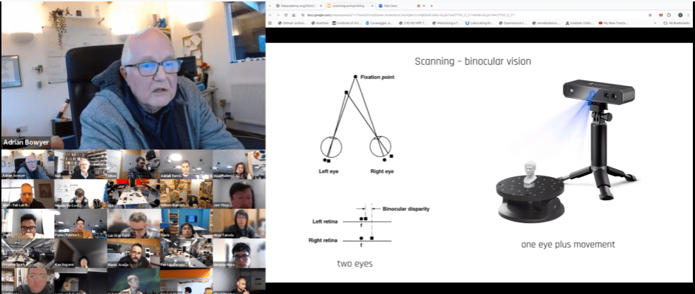
During the theory class of Week 05, we focused on the fundamentals of 3D printing and 3D scanning. We learned how additive manufacturing works, the different types of 3D printers, materials, and slicing settings such as layer height, infill, supports, and print speed. We also explored how 3D scanning captures real-world objects and converts them into digital models.
This helped me understand how digital designs can be transformed into physical prototypes through additive manufacturing, and how existing objects can be digitized for modification or reproduction. It was an important step toward developing accurate and functional parts for my final project.
Group Assignment:
° Test the design rules for your 3D printer(s)
° Document your work on the group work page and reflect on your individual page what you learned about characteristics of your printer(s)
individual Assignment:
° Design, document and 3D print an object (small, few cm3, limited by printer time) that could not be easily made subtractively
° 3D scan an object (and optionally print it)
Have you answered these questions?
- I. Linked to the group assignment page. ✅
- II. Explained what you learned from testing the 3D printers✅
- III. Documented how you designed and 3D printed your object and explained why it could not be easily made subtractively ✅
- IV. Documented how you scanned an object ✅
- V. Included your original design files for 3D printing. ✅
- VI. Included your hero shots✅
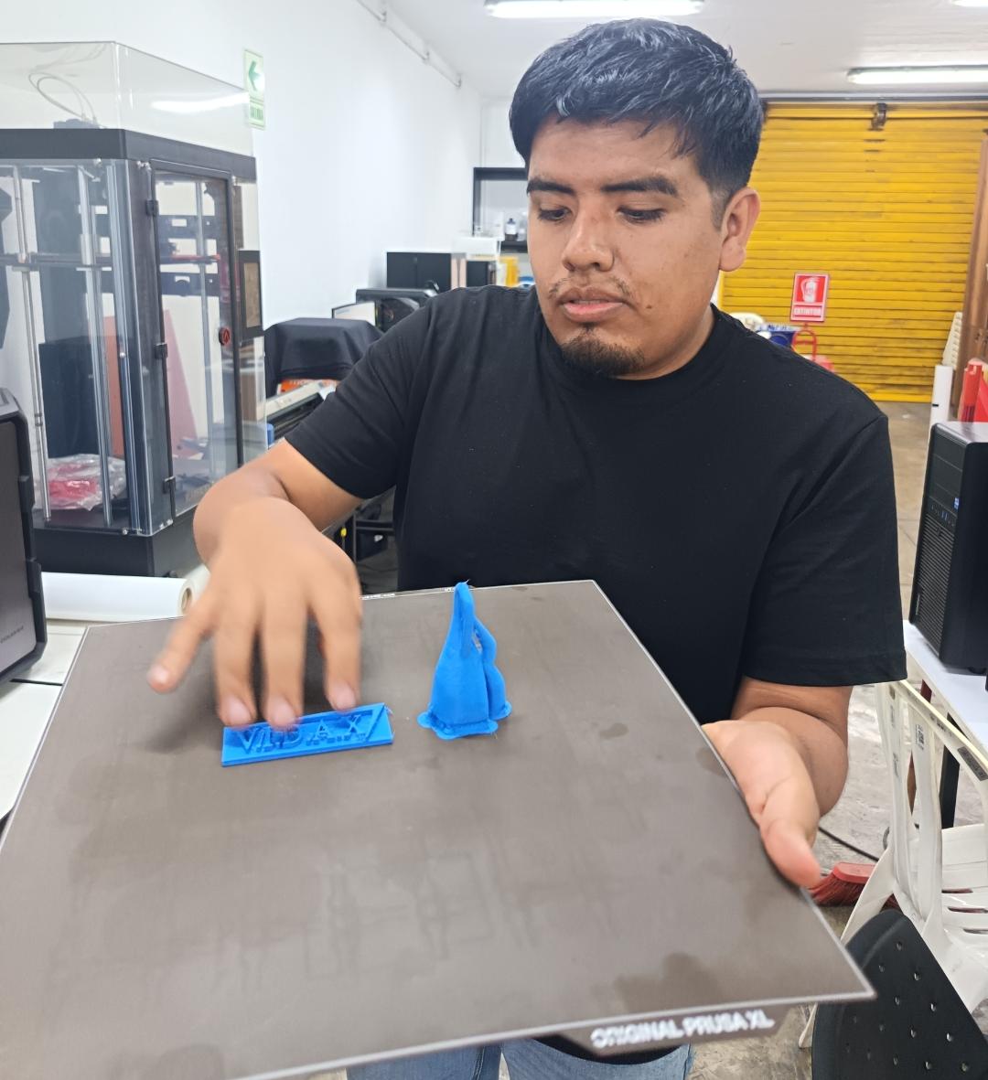
2.1 Hero Shot:
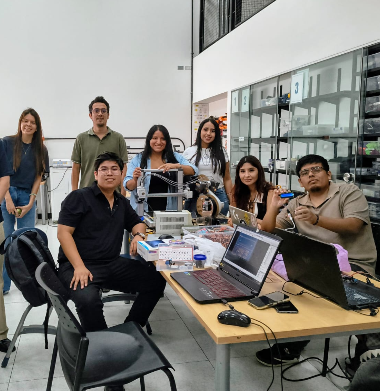
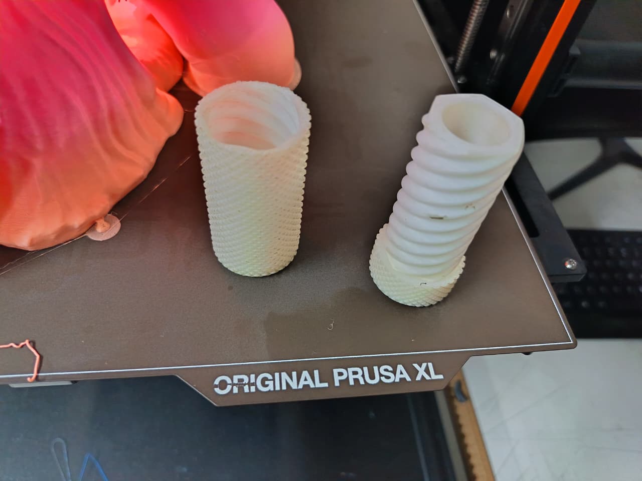
This image shows the final result of my assignment 3D Scanning and Printing. The printed object was successfully fabricated using an FDM 3D printer, after scanning the object demonstrating the ability to create complex geometries that would be difficult to produce using subtractive manufacturing methods. The design includes detailed and organic shapes that take advantage of additive manufacturing, allowing the piece to be printed layer by layer with good precision and stability.
The photograph also documents the moment after completing the print, presenting both the finished object on the print bed and me holding the final result inside the fabrication laboratory. This hero shot highlights not only the successful fabrication process but also the scale, surface quality, and overall outcome of the assignment, serving as the main visual representation of my work for this week.
.png)
Group Assignment Sumary
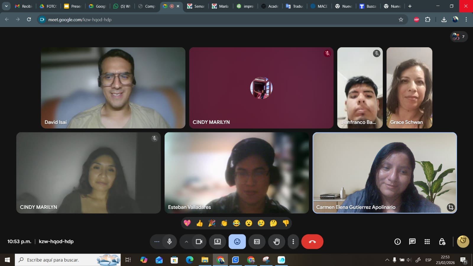
Before starting my individual work, we organized a Zoom meeting to coordinate the group assignment. During the meeting, we discussed the type of 3D printers each of us had access to, as well as the printing parameters and slicer software we were going to use for our tests. This allowed us to compare configurations and better understand how different settings affect print quality and material behavior, helping me define the most suitable parameters for my own work.
Here is the link to learn more about the group project.
🤝 Group Assignment Reflection
During the group assignment, we tested and analyzed the design rules and limitations of the 3D printers available in our lab. Through different print tests, we evaluated characteristics such as overhangs, bridging, tolerances, layer adhesion, support requirements, and dimensional accuracy. These experiments helped me better understand how printer settings and geometry directly affect print quality and how each machine behaves under different fabrication conditions.
From this process, I learned that every 3D printer has specific capabilities and limitations that must be considered during the design stage. I also understood the importance of calibration, correct slicing parameters, and material selection to achieve reliable and accurate prints. Working collaboratively allowed us to compare results, identify common issues, and improve our understanding of additive manufacturing workflows through shared experimentation and discussion.
Here is the link to learn more about the group project.
Introduction:
This week focused on 3D printing and 3D scanning, exploring both the theoretical and practical aspects of these digital fabrication processes. The work started with reviewing the technical specifications of different 3D printers and 3D scanners, understanding their capabilities, limitations, materials, and working principles.
As part of the hands-on activities, I used a 3D scanner to digitize a physical object and then processed the resulting model to prepare it for fabrication. Finally, the scanned piece was replicated using 3D printing, allowing me to complete the full workflow from physical object to digital model and back to a physical replica. This process helped me better understand the relationship between scanning accuracy, model preparation, and print quality.
.png)
Individual Assignment
Design, document and 3D print an object
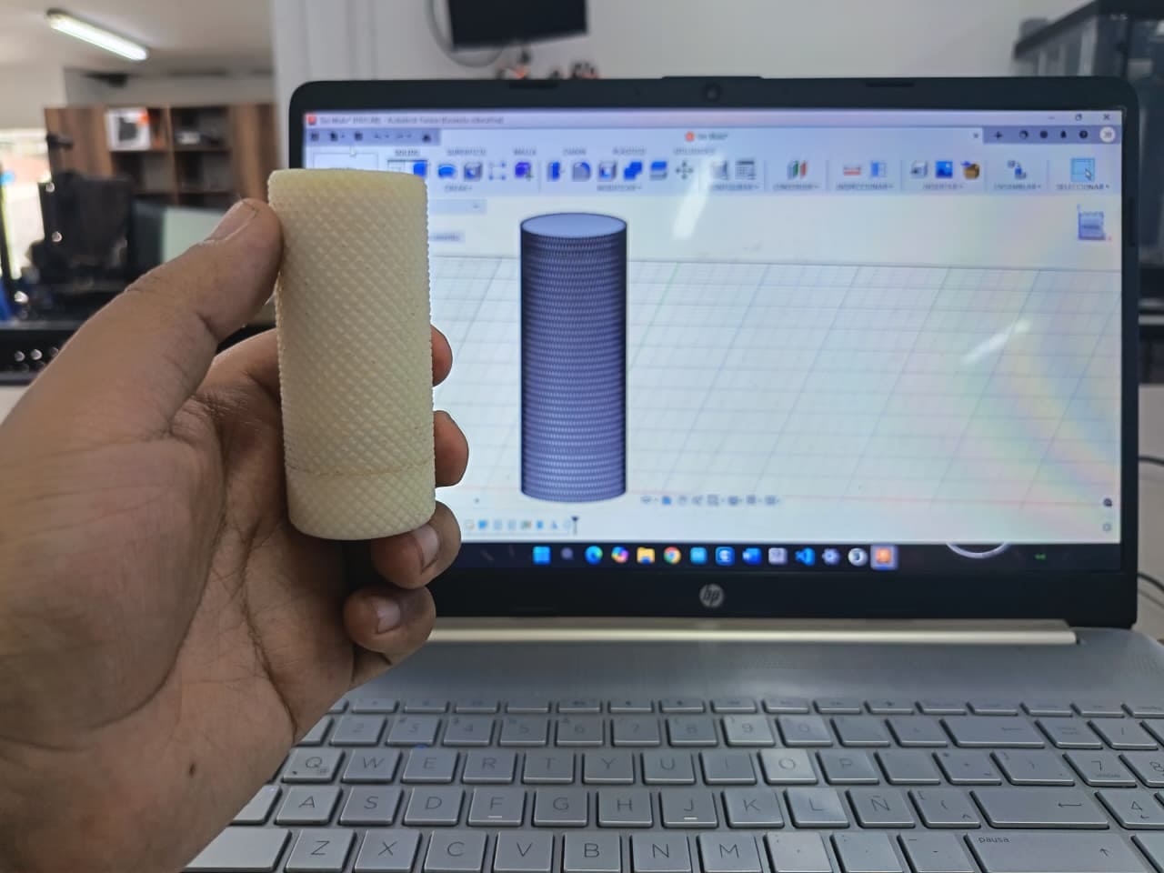
For this assignment, I designed a Knurled Twist container using Fusion 360, focusing on creating a functional object with a threaded twist mechanism and textured grip for better usability. The parametric tools allowed me to adjust dimensions and tolerances to ensure proper fitting between the container and the lid.
After completing the design, the model was exported as an STL file and prepared for 3D printing. The object was then successfully fabricated using a 3D printer, allowing me to test the fit, functionality, and print quality of the container. This process helped validate the design and understand how digital models translate into physical objects through additive manufacturing.
Step-by-Step Design of the Knurled Twist Container in Fusion 360
Design, document and 3D print an object
The images show the step-by-step modeling process of the knurled twist container in Fusion 360. First, the basic cylindrical shapes for the container body and lid were created. Then, the internal hollow and wall thickness were defined to ensure printability. After that, the threaded geometry was added to both parts to allow a twist-to-open mechanism, and the internal section view was used to verify clearances and proper fitting between the threads. This step-by-step approach helped validate tolerances, assembly, and functionality before exporting the final model for 3D printing.
Knurled Twist Container – 3D Design in Fusion 360
°The image shows the 3D design of a knurled twist container in Fusion 360, composed of two main parts: the outer container body and the threaded inner lid. The external surface features a knurled texture to improve grip, while the internal component includes a threaded mechanism that allows the container to open and close by twisting. The model is displayed in an exploded view to verify tolerances, alignment, and proper assembly before exporting the design for 3D printing.
.png)
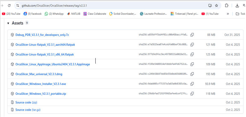
Orca Slicer software download
°To perform 3D printing with the Prusa XL 3D printer using Orca Slicer , an open-source program, the first thing we need to do is download the program from the GitHub folder and then install it on our PC. Once the program is installed, its configuration is extremely easy. We choose the type of printer where we will do our 3D printing and the material we will use, and the next step is to import the .STL file.
Orca Slicer installation process
Microcontroller Selection: Raspberry pico 2040 Microcontroller
I follow the download process, accept the License Agreement, select the folder where I want to save the file, and choose the type of printer I will be using.
.png)
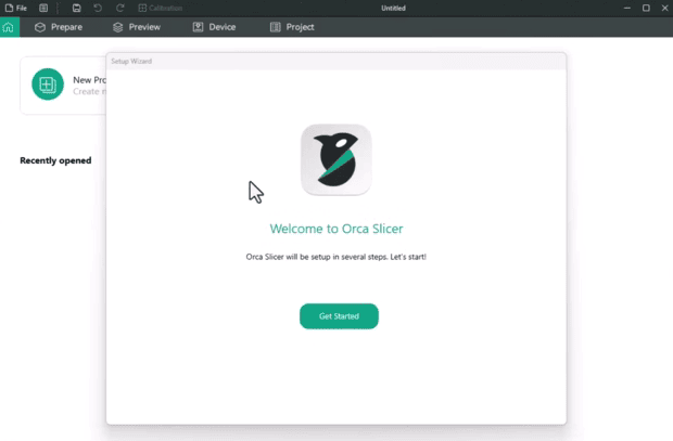
Setup Orca Slicer
1)Once the installation process is complete and the configuration window opens, proceed to click Get Started
2)During the initial setup of the 3D printer/scanner software, I was prompted to select the login region. From the available options (Asia-Pacific, China, Europe, North America, and Others)

3)In this step we proceed to select the model of our printer which in my case will be the Prusa XL
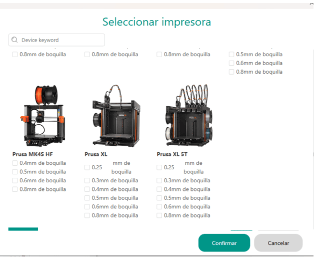
4)In this step we proceed to select the model of our printer which in my case will be the Prusa XL
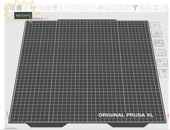
5)At this step we will be able to visualize the work area and the parameters we will use to generate our slicers
.png)
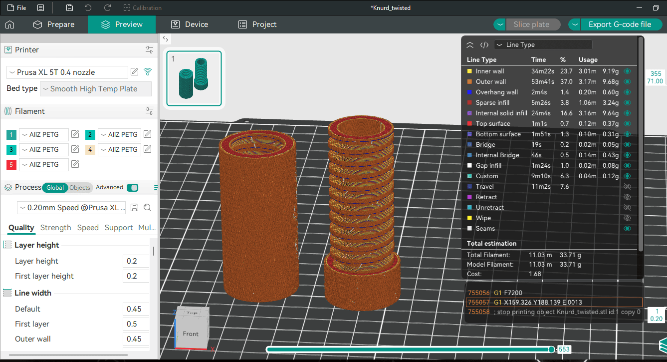
Slicing the Model (G-code Generation)
In this part we proceed to import the 3D model that was previously created in Fusion360
Here I open the stl file into the slicer
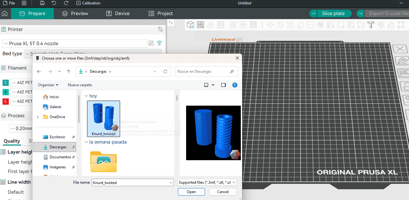
Here I open the stl file into the slicer
Printer Setup
Once the G-code was generated, I prepared the 3D printer: Loaded the PLA+ filament. Pre-heated the nozzle and bed. Transferred the G-code via USB because the 3d printer Prusa has a own USB. Calibrated the bed automatically.
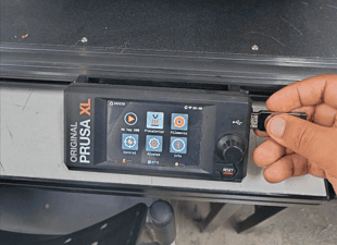
Click in Print
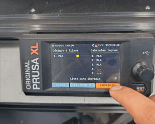
🧩 Printing and Monitoring
This image documents the 3D printing and monitoring process of the objects designed for the assignment “Design, document and 3D print an object that could not be easily made subtractively.” The pieces were fabricated using an Original Prusa XL FDM 3D printer, where the layer-by-layer additive manufacturing process allowed the creation of complex spiral and threaded geometries that would be very difficult to produce using traditional subtractive methods such as CNC machining.
During the printing process, I continuously monitored important factors such as layer adhesion, print stability, extrusion consistency, and surface quality to ensure successful fabrication. The detailed helical patterns and internal geometries required precise printing settings and careful observation to avoid defects or printing failures. This stage helped me better understand the importance of machine calibration and real-time supervision during additive manufacturing workflows.
3D Scanning
To complete the installation of the EinScan HX software, I followed the standard setup process. After selecting the language, I clicked Next, then accepted the license agreement by selecting “I Agree”. After that, I continued by pressing Next twice to confirm the default installation settings and destination folder. Finally, I clicked Install to begin the installation process.
These steps allowed me to properly set up the 3D scanning software required for this week’s assignment on 3D printing and 3D scanning.
.png)
Launched EXScan
After completing the installation process, I launched the EXScan HX software to verify that everything was working correctly. The startup screen displayed the SHINING 3D branding, the software name EXScan HX, and version 1.4.1.3, confirming that the installation was successful. A loading bar appeared while the program initialized, indicating that the system was preparing the scanning environment.
.png)
Scan Calibration
In this stage, I performed the laser calibration process using the EinScan HX scanner. On the left side of the screen, the EXScan HX software shows the calibration interface, where different options such as Laser Calibration, White Balance, and Standard Calibration are available. The instructions guide the user to correctly position the calibration board and align the scanner vertically to ensure accurate results.
On the right side, I am holding the scanner and positioning it carefully in front of the calibration board. This step is essential to guarantee precise measurements and accurate 3D scanning results. Proper calibration ensures that the scanner captures geometry correctly, reducing errors and improving the overall quality of the digital model.
.png)
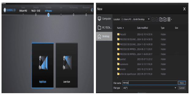
Open a New Project
This image shows the initial setup process in the Shining 3D software, which is the official software used with the EinScan HX 3D scanner available at FABLAB UNI. To begin the scanning workflow, I created a new project and selected the appropriate scanning mode according to the type of object and level of detail required. The software interface allows project organization, scan configuration, and file management before starting the digitization process.
Using the EinScan HX together with the Shining 3D software provided a professional workflow for capturing real-world objects and converting them into digital 3D models. This step was important to properly organize the scanning session and ensure that all the captured data would be stored and processed correctly during the assignment.
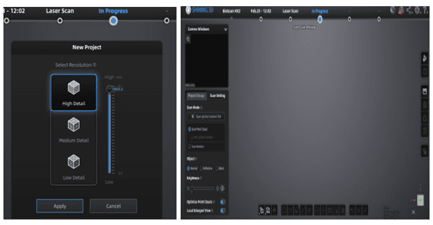
Scan Mode_In Progress
This image documents the scanning process while using the EinScan HX 3D scanner together with the official Shining 3D software at FABLAB UNI. During this stage, the scanner actively captured the geometry and surface details of the object in real time, generating a digital representation point by point as the scan progressed. The software continuously displayed the scanned areas, helping to identify missing regions and maintain proper tracking throughout the process.
While scanning, it was important to move the scanner steadily around the object to ensure accurate alignment and complete surface coverage. This process allowed me to better understand how professional 3D scanning workflows operate, including tracking, mesh generation, and real-time visualization of captured data.
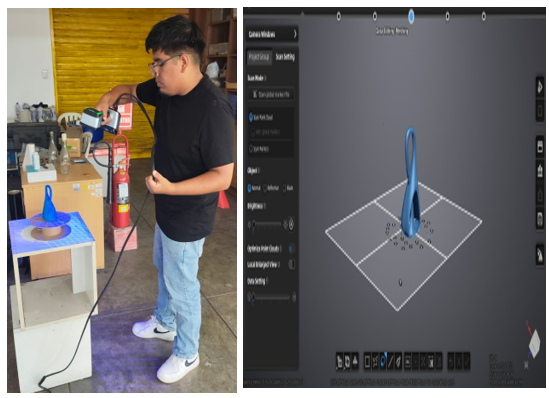
Scan Mode_In Progress
This image shows the active 3D scanning process carried out using the EinScan HX scanner together with the Shining 3D software at FABLAB UNI. On the left side, the scanning procedure can be seen while capturing the geometry of the object from different angles to obtain complete surface information. On the right side, the software displays the digital model being generated in real time, allowing immediate visualization of the scanned geometry and helping identify areas that still required additional capture.
During the process, I carefully moved the scanner around the object while maintaining stable tracking and consistent distance to improve scan accuracy. The software continuously processed the captured data and reconstructed the digital mesh, demonstrating how physical objects can be transformed into editable 3D models through reverse engineering and digital fabrication technologies.
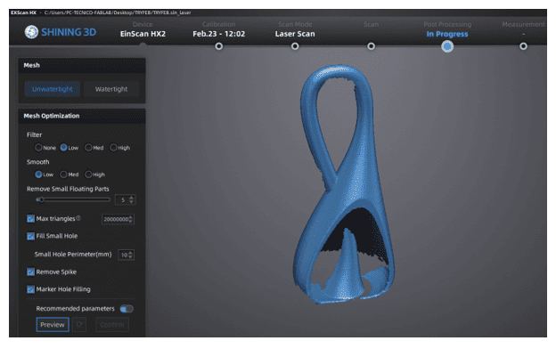
Post processing
After completing the 3D scanning process, I performed post-processing inside the Shining 3D software to improve the quality of the final digital model. This stage included cleaning unwanted scan data, removing floating artifacts, aligning the captured geometry, and refining the mesh to obtain a smoother and more complete result. I also checked for missing areas and optimized the surface details to ensure that the final model was properly reconstructed and ready for export or future fabrication processes such as 3D printing or digital visualization.
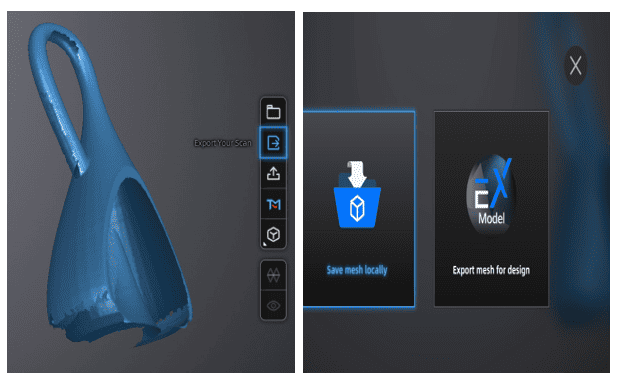
Export Mesh
Once the post-processing stage was completed, I exported the final 3D model as a mesh file for future use in digital fabrication and visualization workflows. The model was prepared and optimized before export to ensure that the geometry was clean, complete, and compatible with other 3D software. This step allowed the scanned object to be saved in a standard 3D format, making it possible to later edit, analyze, or fabricate the model using additive manufacturing technologies such as 3D printing.
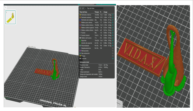
Import .Stl in OrcaSlicer
After exporting the scanned model as an STL file, I imported it into OrcaSlicer to prepare it for the 3D printing workflow. Inside the software, I verified the orientation, scale, and positioning of the model on the print bed to ensure proper fabrication. OrcaSlicer also allowed me to configure important printing parameters such as layer height, supports, infill, and print speed before generating the G-code file. This step was essential to transform the scanned mesh into a printable object ready for additive manufacturing.
Final Result 🏁
The final result demonstrates the successful integration of 3D scanning and additive manufacturing processes throughout the assignment. After scanning the object with the EinScan HX, performing mesh post-processing, and preparing the STL file in OrcaSlicer, the model was successfully fabricated using 3D printing technology. The final printed piece preserved the main geometry and overall shape of the scanned object, showing how digital fabrication tools can accurately transform real-world objects into physical reproductions through a complete reverse engineering workflow.
📚 What I Learned from Testing the 3D Printers
By testing different 3D printing configurations during this assignment, I learned how important printer calibration and parameter selection are for achieving successful results. Factors such as layer height, print speed, nozzle temperature, bed adhesion, and support generation directly affected the surface quality, dimensional accuracy, and stability of the printed objects. I also understood that complex geometries require careful orientation and slicing preparation to avoid print failures and improve the final finish.
Additionally, working with the printers helped me better understand the limitations and advantages of additive manufacturing compared to subtractive methods. I observed how 3D printing makes it possible to fabricate internal geometries, curved structures, and intricate shapes that would be difficult or impossible to produce with traditional machining processes. This experience improved my understanding of the complete digital fabrication workflow, from design preparation to final physical production.
💭 Individual Assignment Reflection
This assignment helped me better understand the complete workflow of additive manufacturing and 3D scanning, from digital design and slicing preparation to fabrication and reverse engineering. Through the 3D printing process, I learned how different parameters influence print quality and how careful monitoring is necessary to achieve accurate and stable results. At the same time, using the EinScan HX scanner allowed me to explore professional 3D digitization workflows and understand how physical objects can be converted into editable digital models.
One of the most valuable parts of this assignment was comparing digital fabrication processes and recognizing the strengths of additive manufacturing for creating complex geometries that cannot be easily produced subtractively. Overall, this experience improved my technical skills in modeling, scanning, slicing, and fabrication while reinforcing the importance of experimentation, calibration, and iterative problem-solving in digital fabrication projects.
Files
Here are the project files available for download:
- Stl Knurd_twisted: Download .stl
- File in Fusion 360: Download .f3d
- Stl Scan Model: Download .stl