Week 04
Embedded Programming
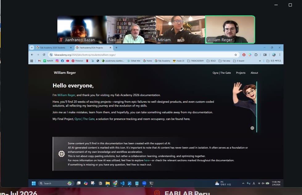
Class with Neil
During the theory class of Week 04, we learned about the basics of embedded programming and how microcontrollers work. We studied how code is uploaded to a board, how digital and analog pins function, and how to control external components such as LEDs, buttons, sensors, and motors through programming.
This helped me understand how software can control physical hardware, how to structure simple programs, and how embedded systems interact with real-world inputs and outputs. It was an important step toward making my final project intelligent and interactive.
Group Assignment:
° Demonstrate and compare the toolchains and development workflows for available embedded architectures
° Document your work to the group work page and reflect on your individual page what you learned
Individual Assignment:
° Browse through the datasheet for a microcontroller
° Write and test a program for an embedded system using a microcontroller to interact (with local input &/or output devices) and communicate (with remote wired or wireless connections)
Have you answered these questions?
- I. Linked to the group assignment page. ✅
- II. Browsed and documented some information from a microcontroller's datasheet✅
- III. Programmed a board to interact and communicate ✅
- IV. Described the programming process(es) you used ✅
- V. Included your source code. ✅
- VI. Included ‘hero shot(s)’ ✅
Group Assignment Sumary
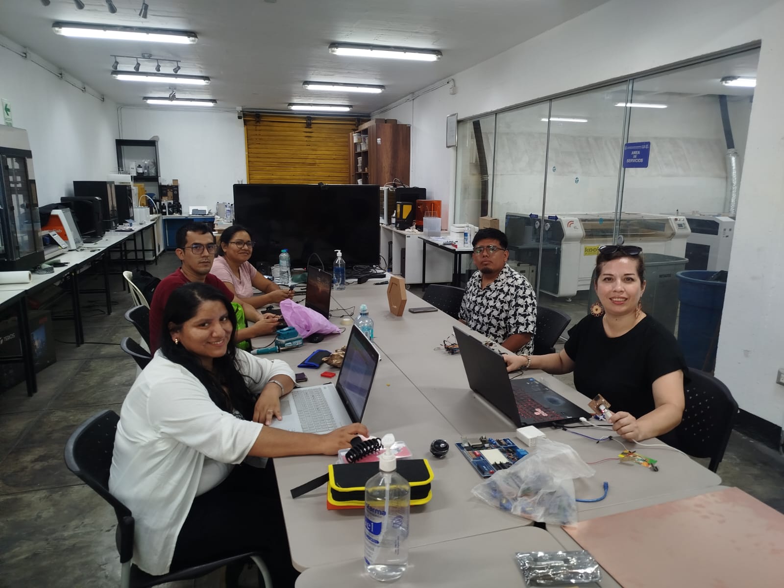
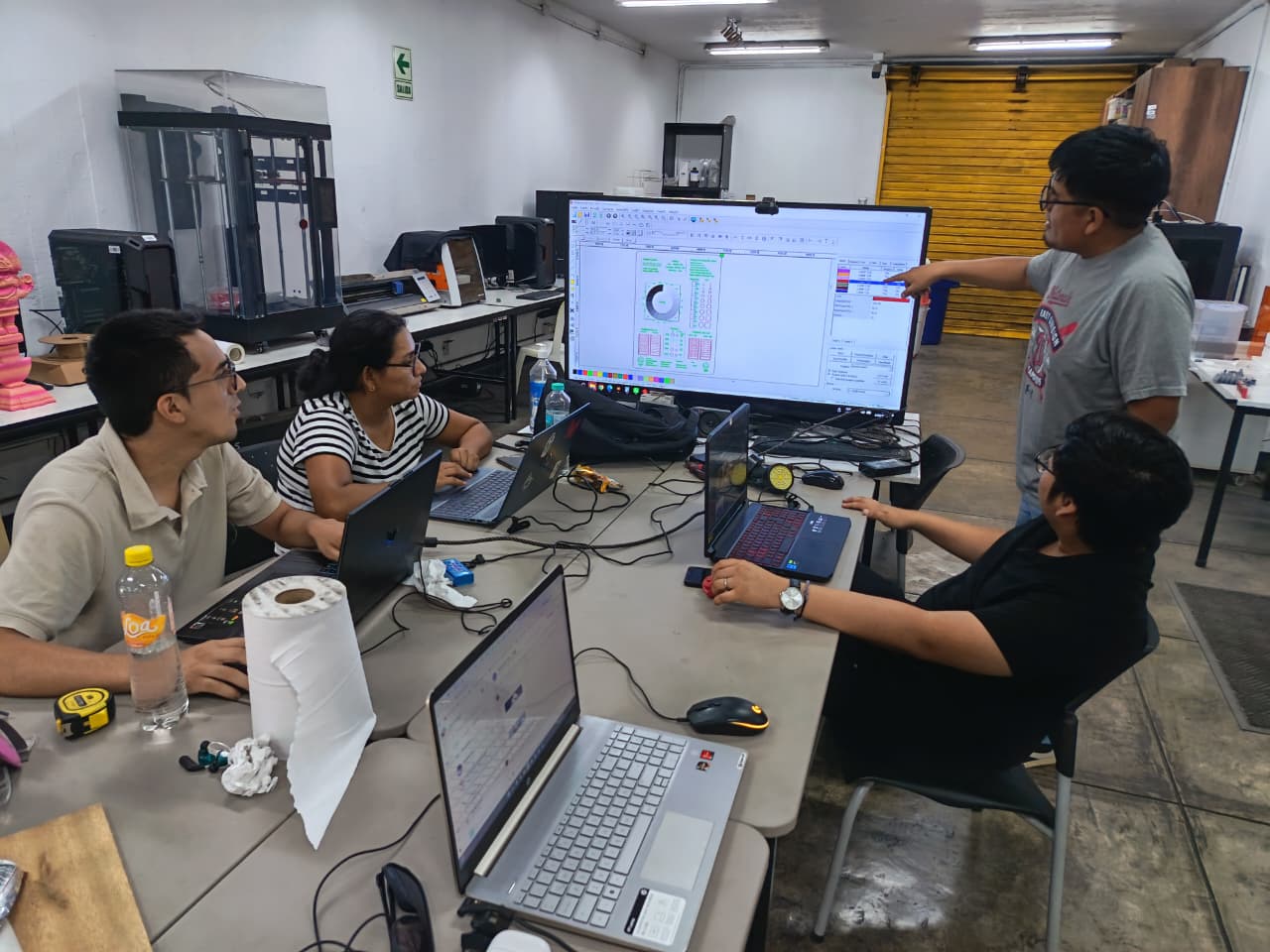
Before beginning my individual work, we ran several group tests to check the laser kerf, engraving strength, and cutting speed. These trials helped me better understand how the material reacts to different settings and allowed me to choose the best parameters for my own design. And for this Assignment we decide make our Assignment in the FAB LAB UNI.
Here is the link to learn more about the group project.
Introduction:
This week focused on embedded programming and understanding how code can control physical devices. I learned how microcontrollers work, how to upload programs, and how to interact with electronic components such as LEDs, buttons, and sensors.
This week was essential for my final project, since the pill dispenser will rely on embedded systems to process inputs, control actuators, and make decisions. Learning how software and hardware communicate opened the door to creating a truly interactive and functional device.
IntroIndividual Reflection – Group Assignmentduction:
For the group assignment, I contributed mainly to the hardware integration by carefully soldering the components and header pins to ensure solid and reliable electrical connections. I paid close attention to alignment, solder quality, and avoiding cold joints, since these small details directly impact the stability of the system. Additionally, I was responsible for organizing the circuit on the breadboard, making sure that all connections were clear, well-structured, and easy to debug if needed.
This experience reinforced the importance of good practices in electronics assembly, not only at the programming level but also in the physical implementation of the circuit. A clean and well-organized setup helped the team work more efficiently and reduced potential errors during testing. It also allowed me to better understand how hardware and software must work together in embedded systems to achieve reliable and consistent results.
Individual Assignment:
For this assignment, I reviewed the datasheet of my microcontroller and developed a program to control and test its behavior. I simulated and then implemented the system to interact with local input and output devices, using a touch sensor as input and an OLED display as output.
To extend the system, I also worked with a Raspberry Pi Pico and an ESP32-S3, allowing communication between boards through wired and wireless connections. This helped me understand how different microcontrollers can exchange data and work together in a single system.
Instructor's Guide
To begin this assignment, I contacted my instructor Evelyn to ask for guidance and confirm the components I would need. Since I already have experience in electronics, I prepared my own list of parts and planned the system according to the requirements of the project.
After that, I went to Paruro, Lima, to purchase the remaining electronic components. This process allowed me to select the correct parts, manage my budget, and ensure compatibility with the microcontrollers I would be using.
Tutorial
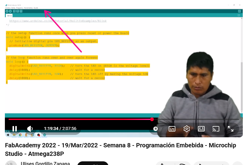
°On February 16th, I found a master class prepared by Ulises Gordillo in Spanish, where he explained how to use programming languages such as Arduino API, C++, and MicroPython. During the session, he shared resources and practical examples that showed how these languages can be applied to real electronics projects.
Exploring Arduino IDE
In this stage, I explored the Arduino IDE as the main platform for programming embedded systems. Using this environment, I was able to write, compile, and upload code to the RASPBERRY PI 2040, allowing me to test different functionalities and understand how software interacts with hardware.
I also became familiar with key tools such as the code editor, toolbar, and serial monitor, which helped me debug and monitor system behavior in real time. Additionally, I learned how to configure the correct board, select the communication port, and install libraries, ensuring proper operation of my projects. ⚙️💻
.png)
Programming Protocol
Microcontroller Selection: Raspberry pico 2040 Microcontroller
| Feature | Specification |
|---|---|
| Microcontroller | RP2040 (Dual-core ARM Cortex-M0+) |
| Clock Speed | Up to 133 MHz |
| Flash Memory | 2 MB QSPI Flash |
| SRAM | 264 KB |
| Operating Voltage | 1.8 – 5.5 V (via VSYS) |
| Logic Level | 3.3 V |
| GPIO Pins | 26 multifunction GPIO |
| ADC | 3 × 12-bit ADC + internal temperature sensor |
| PWM | 16 PWM channels |
| UART | 2 |
| I2C | 2 |
| SPI | 2 |
| USB | USB 1.1 device & host support |
| Temperature Sensor | On-chip sensor |
| Programmable I/O | PIO (2 blocks, 4 state machines each) |
| Dimensions | 51 × 21 mm |
The Raspberry Pi Pico (RP2040) is a powerful and low-cost microcontroller board designed for embedded projects. It features a dual-core ARM Cortex-M0+ processor, flexible GPIO pins, and supports multiple programming languages such as MicroPython, C/C++, and Arduino. Its versatility and performance make it ideal for handling sensors, displays, and communication modules in compact electronic systems.
.png)
Programming Protocol
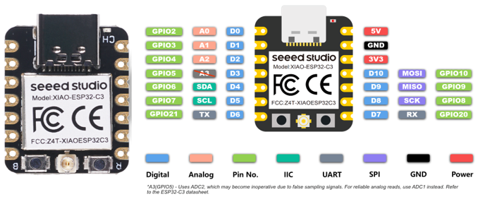
Microcontroller Selection: ESP32 S3
ESP32-3c – Features & Specifications
| Feature | Specification |
|---|---|
| Microcontroller | Xtensa® LX7 Dual-core 32-bit |
| Clock Speed | Up to 240 MHz |
| SRAM | 512 KB |
| Flash Memory | Up to 16 MB (external) |
| Operating Voltage | 3.0 – 3.6 V |
| Logic Level | 3.3 V |
| GPIO Pins | Up to 45 programmable GPIO |
| Wi-Fi | 2.4 GHz 802.11 b/g/n |
| Bluetooth | Bluetooth 5 (LE) |
| ADC | 2 × 12-bit ADC (20 channels) |
| DAC | 2 × 8-bit DAC |
| PWM | Up to 8 PWM channels |
| UART | 3 |
| I2C | 2 |
| SPI | 3 |
| USB | USB 2.0 OTG (device/host) |
| Camera Interface | 8/16-bit parallel camera interface |
| AI Acceleration | Vector instructions for ML acceleration |
| Security | Secure boot, flash encryption, AES, RSA, SHA |
The Raspberry Pi Pico (RP2040) is a powerful and low-cost microcontroller board designed for embedded projects. It features a dual-core ARM Cortex-M0+ processor, flexible GPIO pins, and supports multiple programming languages such as MicroPython, C/C++, and Arduino. Its versatility and performance make it ideal for handling sensors, displays, and communication modules in compact electronic systems.
Why I Chose Raspberry Pi RP2040
For this assignment, I decided to work with the Raspberry Pi RP2040 because it was the microcontroller I had available at the moment. Since my XIAO ESP32 S3 had not yet arrived, using the RP2040 allowed me to continue progressing with the weekly tasks without delays.
Even though it was not my initial choice, working with the RP2040 helped me understand that embedded programming concepts can be applied across different platforms. This experience allowed me to adapt my workflow and continue developing my skills while waiting to integrate the ESP32-S3 into future assignments. ⚙️💻
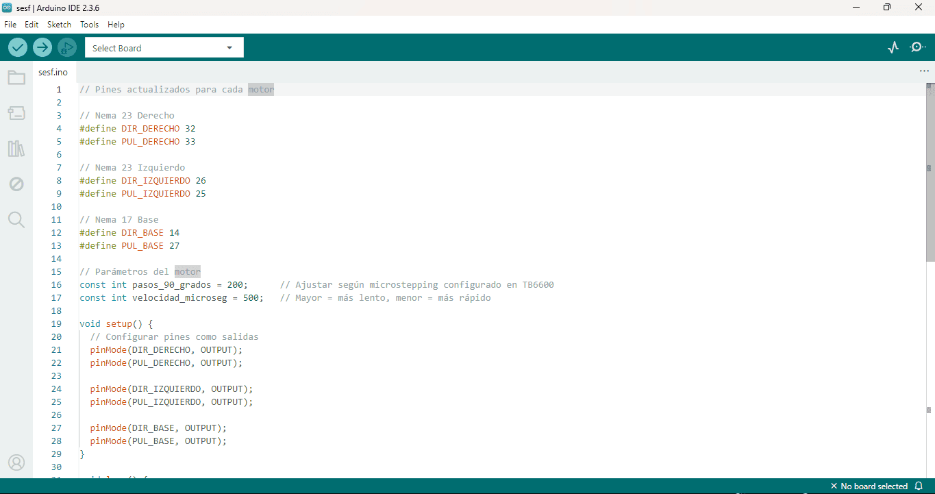
Setup Arduino IDE
At this stage, the development environment Arduino IDE (v2.3.6) was configured to program the Raspberry Pi Pico based on the RP2040; a sketch was created where the DIR and PUL pins were defined to control three stepper motors using drivers such as the TB6600, adjusting step and speed parameters, and setting all pins as outputs in setup(), leaving the system ready for motion testing and further hardware integration.
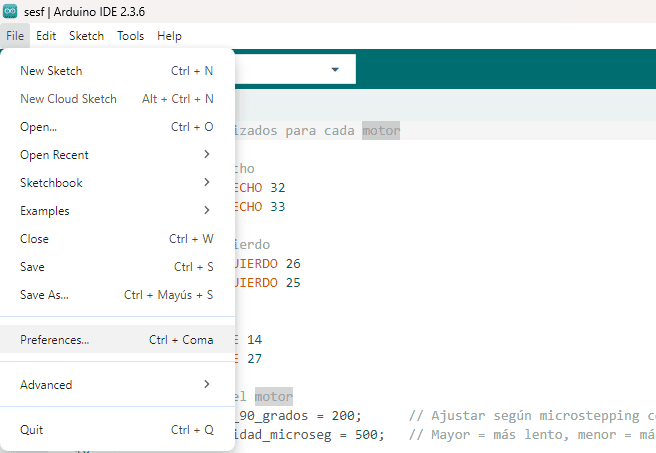
⚙️Accessing Preferences in Arduino IDE
In this step, the Arduino IDE (v2.3.6) interface is shown with the File menu open, highlighting the Preferences option, which is where the necessary settings are configured to enable support for the Raspberry Pi Pico based on the RP2040. This section is essential for adding additional board manager URLs and adjusting the IDE configuration so that new boards and cores can be installed, allowing the development environment to properly recognize and program the Raspberry Pi Pico for upcoming embedded programming tasks.
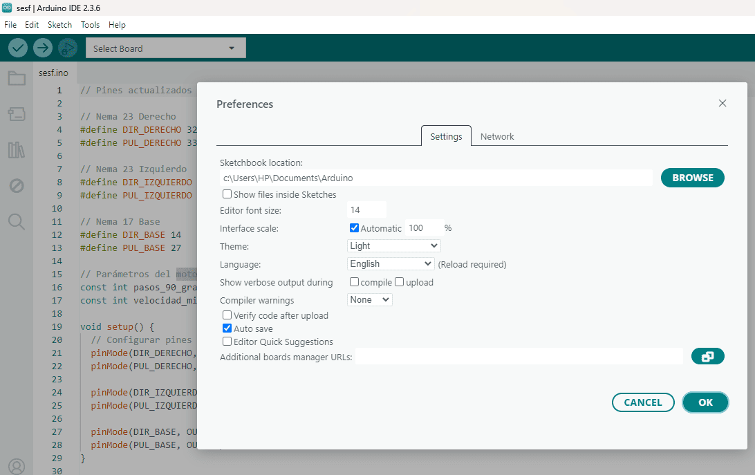
⚙️ Accessing Preferences in Arduino IDE
Here, the Arduino IDE (v2.3.6) Preferences window is shown, where key settings are adjusted to prepare the environment for programming the Raspberry Pi Pico powered by the RP2040. This step is crucial because the “Additional Boards Manager URLs” field is where the RP2040 core repository is added, enabling the IDE to recognize and install support for the Raspberry Pi Pico and related boards, ensuring the toolchain is fully ready for compiling and uploading embedded projects.
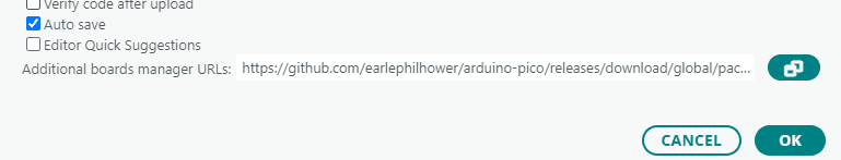
⚙️ Adding the RP2040 Board Manager URL
In this step, the Arduino IDE Preferences panel shows the “Additional Boards Manager URLs” field filled with the repository link needed to install support for the Raspberry Pi Pico, which runs on the RP2040. By adding this URL (from the Arduino-Pico core maintained by Earle Philhower), the IDE can download and install the correct board definitions and tools, enabling proper compilation and upload of sketches to the Raspberry Pi Pico.
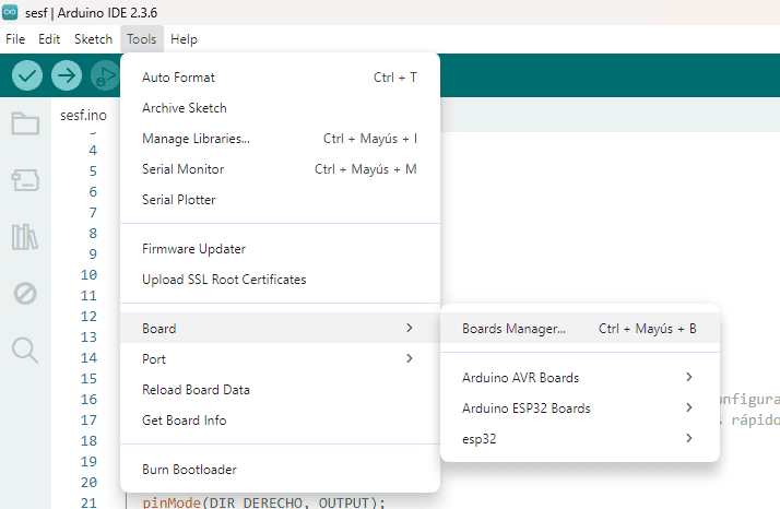
🧩 Installing Board Support from Boards Manager
In this step, the Arduino IDE (v2.3.6) menu path Tools → Board → Boards Manager is opened to install the necessary board packages. This is where you search for and install support for the Raspberry Pi Pico (RP2040 core) after adding the Boards Manager URL, allowing the IDE to recognize the board, enable compilation for the RP2040, and make it available for selection before uploading your sketches.
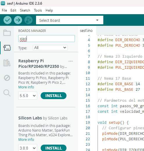
📦 Installing the RP2040 Core from Boards Manager
Here, the Boards Manager inside Arduino IDE (v2.3.6) is used to search for and install the board package for the Raspberry Pi Pico (RP2040 family). After adding the additional Boards Manager URL, the Raspberry Pi Pico/RP2040 package appears in the list, and by clicking Install, the IDE downloads the core, drivers, and toolchain needed to compile and upload sketches to boards based on the RP2040, completing the setup to start programming the Pico.
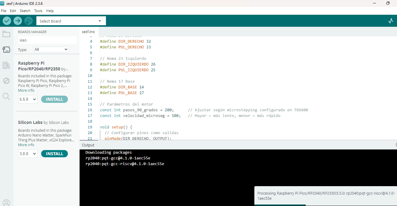
⏳ Downloading and Installing the RP2040 Toolchain
At this point, the Boards Manager in Arduino IDE (v2.3.6) is actively downloading and installing the required packages for the Raspberry Pi Pico family. The output console shows the toolchain components being fetched (such as the RP2040 GCC compilers), which are necessary to compile and upload sketches to boards based on the RP2040. Once this process finishes, the board will be fully available for selection in the IDE and ready for development and testing.
LED Blink Example – Arduino
// LED Blink Example - Arduino

int ledPin = 13;

void setup() {
  pinMode(ledPin, OUTPUT);
}

void loop() {
  digitalWrite(ledPin, HIGH);
  delay(1000);
  digitalWrite(ledPin, LOW);
  delay(1000);
}
This basic program demonstrates how to control a digital output using a microcontroller. The LED connected to pin 13 turns ON and OFF every second, creating a blinking effect. This example is essential to understand timing and digital signal control in embedded programming. 💡
Simulation in Wokwi Led
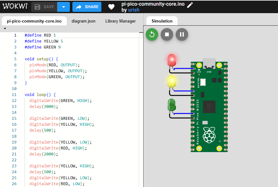
This scene shows a simulation in Wokwi where the Raspberry Pi Pico is being programmed and tested using an Arduino-like sketch. The left panel displays the code that defines three pins (RED, YELLOW, and GREEN) configured as outputs, while the right panel shows the virtual circuit with three LEDs connected to the board. The simulation executes an on/off sequence that mimics a traffic light (green, yellow, and red) with varying delay times, allowing the program logic and connections to be validated before physical implementation on real hardware. 🚦
Code Execution
This step shows the physical setup of a Raspberry Pi Pico mounted on a breadboard and powered via USB from a computer. The onboard LEDs are illuminated, indicating that the board is receiving power correctly and that the uploaded program is running as expected. This quick hardware test helps verify proper power delivery, device recognition by the development environment, and basic functionality before moving on to integrating sensors, actuators, or other modules into the project.
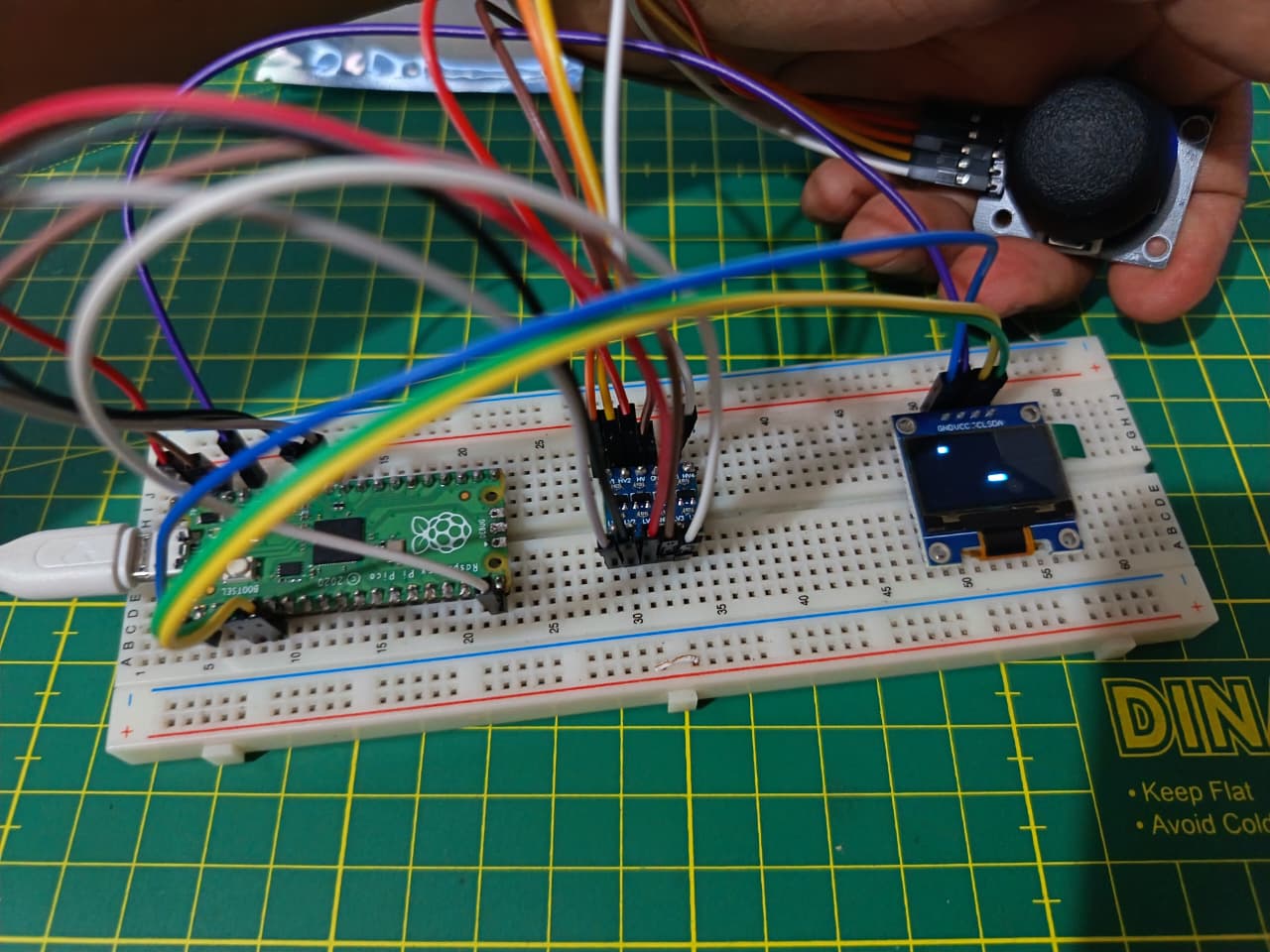
🧩 Joystick and OLED Display Simulation with Raspberry Pi Pico
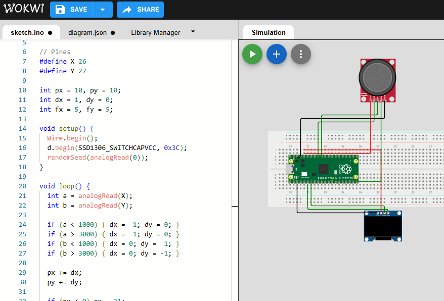
This image shows a simulated electronics setup where a Raspberry Pi Pico is connected on a breadboard to a joystick module and a small OLED display. The wiring links the joystick’s power and signal pins to the Pico’s GPIO and analog inputs, allowing the microcontroller to read directional movements, while the OLED screen is connected via an I²C interface to display real-time feedback or system status. This simulation is useful for validating pin connections and interaction logic in a virtual environment before building the circuit on real hardware, reducing wiring errors and speeding up prototyping.
Code Writing
Joystick OLED Game - Arduino Code
#include <Wire.h>
#include <Adafruit_SSD1306.h>

Adafruit_SSD1306 d(128, 64, &Wire, -1);

// Pines
#define X 26
#define Y 27

int px = 10, py = 10;
int dx = 1, dy = 0;
int fx = 5, fy = 5;

void setup() {
  Wire.begin();
  d.begin(SSD1306_SWITCHCAPVCC, 0x3C);
  randomSeed(analogRead(0));
}

void loop() {
  int a = analogRead(X);
  int b = analogRead(Y);

  if (a < 1000) { dx = -1; dy = 0; }
  if (a > 3000) { dx =  1; dy = 0; }
  if (b < 1000) { dx = 0; dy =  1; }
  if (b > 3000) { dx = 0; dy = -1; }

  px += dx;
  py += dy;

  if (px < 0) px = 31;
  if (px > 31) px = 0;
  if (py < 0) py = 15;
  if (py > 15) py = 0;

  if (px == fx && py == fy) {
    fx = random(32);
    fy = random(16);
  }

  d.clearDisplay();
  d.fillRect(fx * 4, fy * 4, 4, 4, 1);
  d.fillRect(px * 4, py * 4, 4, 4, 1);
  d.display();

  delay(120);
}
By distributing the slots symmetrically and constraining them to the center of the circle, the design remains balanced and fully adjustable. This allows the same piece to be reused in different configurations, such as building a phone holder or other creative structures depending on the user’s imagination.