Week 03
Computer-Controlled Cutting
1.Class with Neil
During the theory class of Week 03, we learned about the use of the laser cutter and the vinyl cutter, as well as how each of these machines works. We studied their main components, safety rules, and the basic principles behind cutting and engraving. This helped me understand how digital designs are translated into physical cuts and how to choose the correct settings for each material.
2. Have you answered these questions?
- I. Linked to the group assignment page. ✅
- II. Reflected on your individual page what you learned of your labs safety training✅
- III. Explained how you created your parametric design.s ✅
- IV. Documented how you made your press-fit construction kit. ✅
- V. Documented how you made something with the vinyl cutter. ✅
- VI. Included your original design files. ✅
- VII. Included hero shots of your results. ✅
2.1 Hero Shot:
For this assignment, my hero shot represents the final result of my parametric construction kit after completing the laser cutting and assembly process. In this image, I showcase how the pieces fit together accurately thanks to proper kerf compensation and consideration of material thickness, achieving a precise press-fit without the need for adhesives. I also used the same set of pieces to create multiple configurations, demonstrating the flexibility and modularity of the design, which can be adapted into different structures such as a phone holder or other forms. Overall, this image reflects the complete workflow from digital design to physical fabrication, highlighting the accuracy, functionality, and versatility of the final result.
3Group Assignment:
° Do your lab's safety training
° Characterize your lasercutter's focus, power, speed, rate, kerf, joint clearance and types.
° Document your work to the group work page and reflect on your individual page what you learned.
3.1 Group Assignment Sumary
Before beginning my individual work, we ran several group tests to check the laser kerf, engraving strength, and cutting speed. These trials helped me better understand how the material reacts to different settings and allowed me to choose the best parameters for my own design. And for this Assignment we decide make our Assignment in the FAB LAB UNI.
Here is the link to learn more about the group project.
3.2 Introduction:
This week was focused on exploring different digital tools to visualize and refine my final project. It became a space for experimentation, where I worked with raster and vector design, 3D modeling, and basic visualization to better define my ideas.
I also rethought the approach to my project, making it more functional and accessible while keeping digital fabrication in mind. Moving from simple sketches to digital models helped me shape the concept, and switching between different tools allowed me to find the workflow that best fits my design process.
3.3 Raster vs Vector Cutting
In laser cutting, there are two main types of operations: raster and vector. Raster engraving works by moving the laser head line by line, similar to how an inkjet printer works, burning the surface of the material to create images or textures.
On the other hand, vector cutting follows defined paths or lines to cut completely through the material. This method is used for precise shapes, joints, and structural parts like my parametric construction kit.
Understanding the difference between raster and vector operations helped me choose the correct settings depending on whether I wanted to engrave or cut.
3.4 Do your lab's safety training
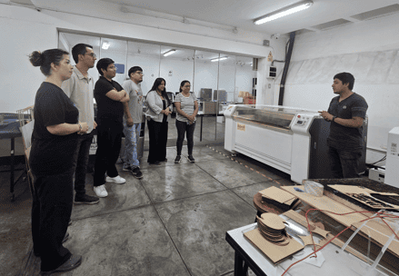
For this project, since I work at the FABLAB UNI, I asked for support from my coworker Jheferson Lados Villegas , who assisted us with our group assignment. He guided us through the different areas of the lab and explained the purpose of each machine, including the laser cutter, vinyl cutter, 3D printers, and CNC equipment.
During the tour, he also verbally explained the safety rules, emergency procedures, and proper use of the machines. He emphasized the importance of wearing personal protective equipment, keeping the workspace clean, and following the correct operating steps. This guidance helped us feel more confident working in the lab and ensured that we followed safe practices throughout the assignment.
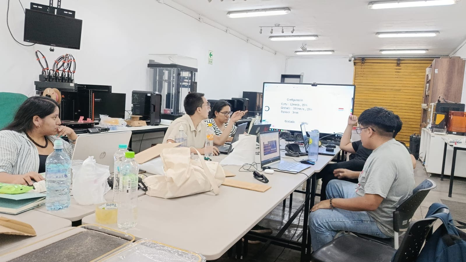
3.5 Parameters of the Laser Cut Machine
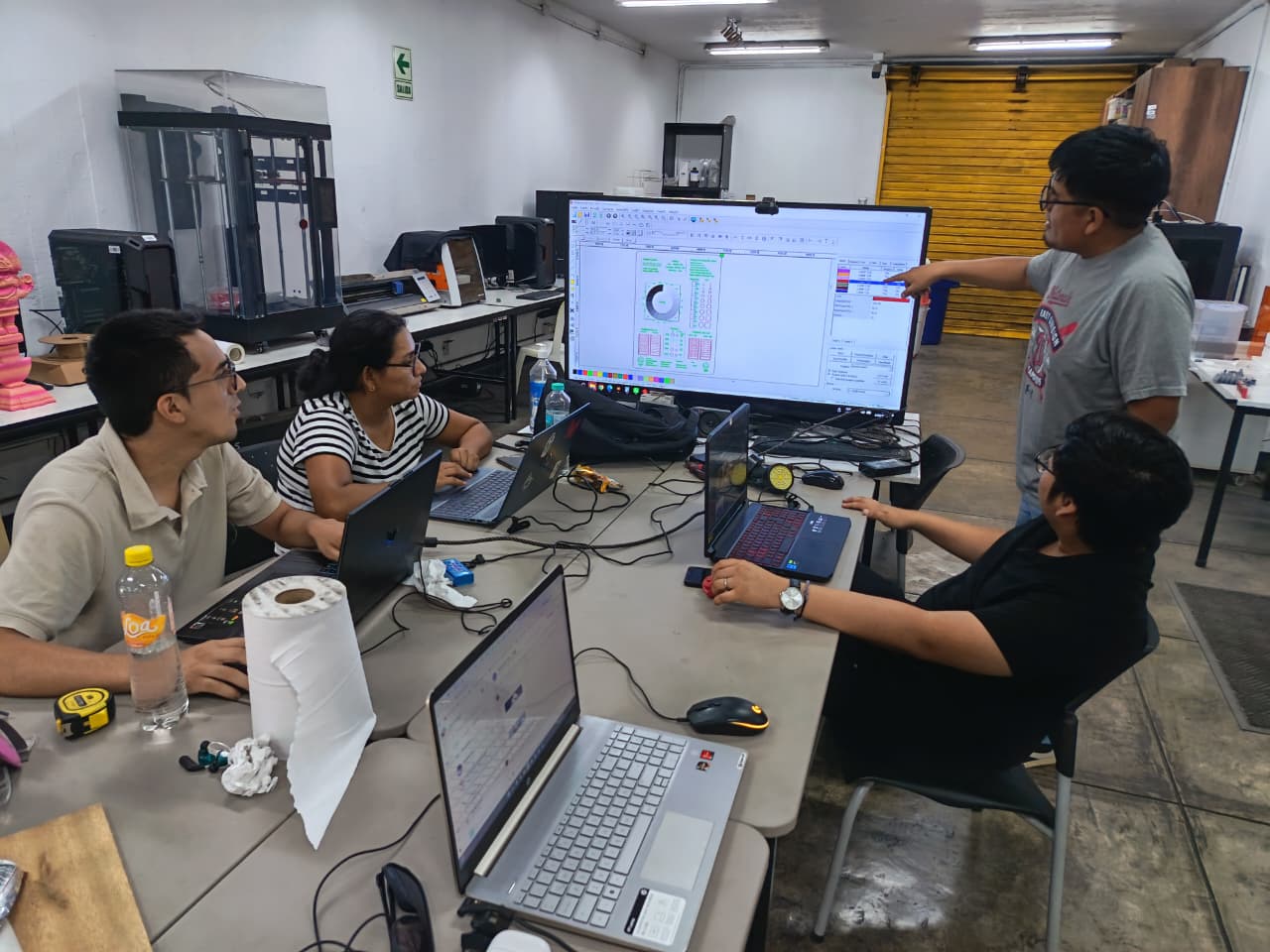
Later, we reviewed the power and speed test results of the laser machine in more detail. During this brief meeting, we analyzed how different settings affected the quality of the cuts and engravings, and we compared which combinations produced the best results. We also discussed the complete laser cutting process, from preparing the vector files to sending them to the machine and adjusting the parameters.
In addition, we talked about the main benefits of using the laser cutter, such as precision, speed, and the ability to create complex shapes. Finally, we reviewed good practices, including checking the focus, cleaning the material surface, and always performing test cuts before working on final pieces.
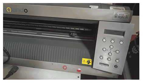
3.6 Vinyl Cutter Recovery
For the vinyl cutter, we faced an additional challenge because the machine had been stored and was not in use. The original software required to operate it was no longer available, which made it impossible to use at first. Because of this, we carried out an extensive search to find a compatible program.
After a thorough search, we finally found a forum where the correct software was available and ready to be downloaded for Windows 10 and Windows 11. Once installed, we were able to reconnect the vinyl cutter and successfully use it to complete the assignment. This experience showed us the importance of problem-solving and adaptability when working with digital fabrication machines.
3.7 Reflection – Week 03
°This week helped me better understand how digital designs become real physical objects. Working with the laser cutter showed me how important it is to test parameters such as power, speed, and kerf before producing final parts, since even small variations can change the fit and quality of the pieces.
° The recovery of the vinyl cutter was also a valuable experience. It taught me that digital fabrication is not only about design and machines, but also about problem-solving when things do not work as expected. Searching for compatible software and bringing an unused machine back to life was both challenging and rewarding.
3.8 Final Result
°This week helped me better understand how digital designs become real physical objects. Working with the laser cutter showed me how important it is to test parameters such as power, speed, and kerf before producing final parts, since even small variations can change the fit and quality of the pieces.
° The recovery of the vinyl cutter was also a valuable experience. It taught me that digital fabrication is not only about design and machines, but also about problem-solving when things do not work as expected. Searching for compatible software and bringing an unused machine back to life was both challenging and rewarding.
4. Individual Assignment
For this week, I completed both required tasks. First, I designed and laser cut a parametric construction kit, taking into account the laser cutter kerf to ensure that all the joints fit correctly. The design was created so that the dimensions and tolerances could be easily adjusted, allowing the pieces to assemble without force or looseness.
Second, I used the vinyl cutter to cut a simple design. This included preparing the vector file, setting the correct cutting parameters, and applying the final vinyl piece. Through this process, I learned how to adapt digital designs for different fabrication machines and materials.
5. Parametric Construction Kit – Laser Cutting & Designt
I designed a parametric construction kit using Autodesk Fusion 360, where I created a sketch with adjustable parameters that allowed me to easily modify the dimensions, tolerances, and joints. The idea of the design was to create a cell phone holder using the parametric kit, but the same pieces can be used to build many other structures depending on the user’s imagination.
5.2 I'm starting to create my model!
I designed a parametric construction kit using Autodesk Fusion 360, where I created a sketch with adjustable parameters that allowed me to easily modify the dimensions, tolerances, and joints. The idea of the design was to create a cell phone holder using the parametric kit, but the same pieces can be used to build many other structures depending on the user’s imagination.
5.3 Fusion 360 – Commands I Used
Here are some of the main commands I used during the modeling process:
| 📌 Command | 🔹 Shortcut | 📋 Description |
|---|---|---|
| ✏ Sketch | Shift + S | Create a new sketch on a plane or face. |
| 🔄 Extrude | Shift + E | Extrude a 2D profile to generate a solid. |
| 📏 Dimension | D | Add dimensions to a sketch. |
| 📐 Constraint | C | Apply geometric constraints. |
| ✂ Trim | T | Trim lines in a sketch. |
| 🔄 Fillet | F | Create a fillet on edges or corners. |
| 📌 Chamfer | Shift + C | Create a chamfer on an edge or corner. |
| 🔗 Mate | M | Join parts in an assembly. |
| 🛠 Hole | H | Create a hole with standard specifications. |
| 🚀 Transform | Shift + T | Move, rotate, or scale an entity. |
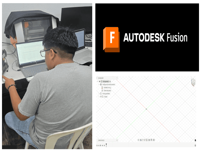
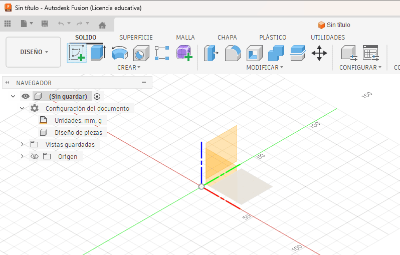
5.4 Parametric Design in Fusion 360
I used Fusion 360 to design my parametric construction kit. I started by opening the program and selecting the Sketch tool, where I created the first outline of my design. From there, I was able to define the main shapes and apply parameters that allowed me to easily modify the dimensions and tolerances of the pieces.
5.5 Parametric Variables in Fusion 360
I used Fusion 360 to design my parametric construction kit. I started by opening the program and selecting the Sketch tool, where I created the first outline of my design. From there, I was able to define the main shapes and apply parameters that allowed me to easily modify the dimensions and tolerances of the pieces.
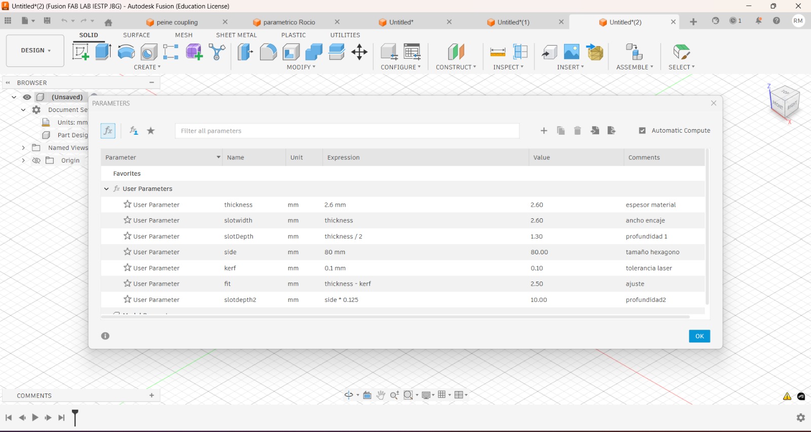
Modify Parameters
In the image, the Change Parameters window from Fusion 360 is shown. Here I defined the main variables that control the entire design of my parametric construction kit. Instead of using fixed dimensions, I used formulas and relations between values so that the model can automatically adapt when one parameter is changed.
Some of the most important parameters are:
- thickness (2.6 mm): material thickness.
- slotwidth = thickness: width of the joint, linked directly to the material thickness.
- slotDepth = thickness / 2: depth of the slot.
- side (80 mm): overall size of the hexagon piece.
- kerf (0.1 mm): laser tolerance.
- fit = thickness − kerf: final joint adjustment to ensure a tight fit.
- slotdepth2 = side × 0.125: secondary depth related to the piece size.
By linking the dimensions with equations, I can quickly adapt the design to different materials or laser cutters just by changing one value, such as the thickness or kerf. This made my construction kit fully parametric and easy to modify for future projects.
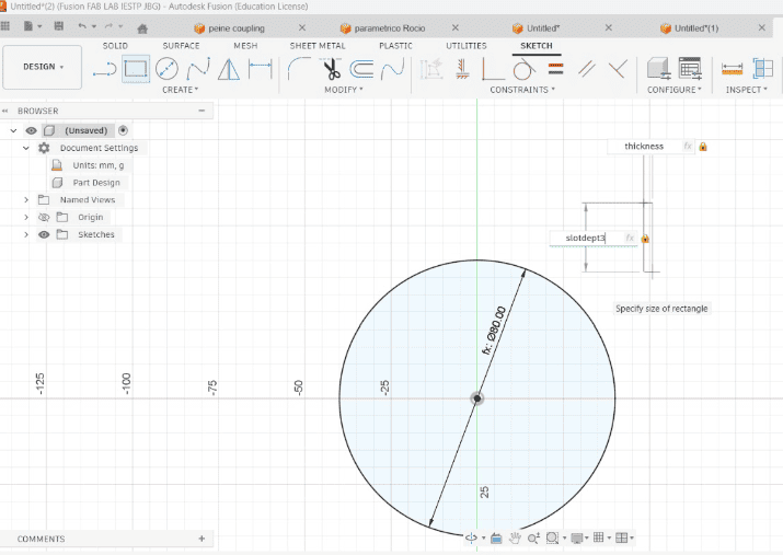
5.6 Parametric Sketch in Fusion 360
In this image, the main sketch of my parametric construction kit can be seen. I created the base geometry using a circle as the main shape, which later becomes the core piece of the kit. The diameter of the circle is linked to a parameter, allowing me to change the overall size of the piece just by editing a single value.
The slots were also created using parametric dimensions. For example, the slot width is connected to the thickness parameter, and the slot depth is linked to the slotDepth value. This means that if I change the material thickness or the kerf, all the joints update automatically without redrawing the sketch.
By using constraints and parameter-based dimensions, the entire design remains fully adjustable. This makes the model flexible for different materials, laser cutters, and assembly tolerances, which is essential for a functional parametric construction kit.
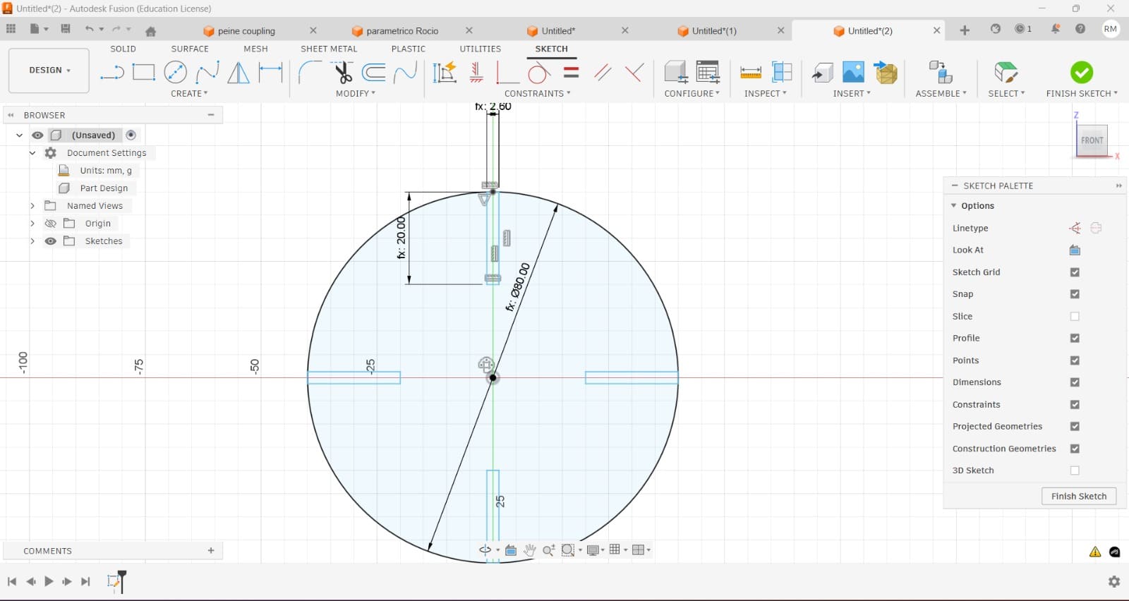
5.7 Slot-Based Parametric Design
In this sketch, I created the main circular piece of my parametric construction kit and added multiple slots around it to allow connections in different directions. The diameter of the circle is linked to a parameter, so the overall size can be changed easily.
Each slot is dimensioned using the parametric variables previously defined, such as thickness, slotwidth, and slotDepth. This ensures that all joints automatically update when the material thickness or kerf is modified.
By distributing the slots symmetrically and constraining them to the center of the circle, the design remains balanced and fully adjustable. This allows the same piece to be reused in different configurations, such as building a phone holder or other creative structures depending on the user’s imagination.
6. Laser Cutting Parameters for DXF File
For the laser cutting process of my DXF file, I configured the cutting parameters in the laser control software according to the material and desired result. The layer was set as Output: Yes, enabling it for fabrication. The cutting speed was set to 25 mm/s, and the process was configured to Cut mode, ensuring a complete cut through the material.
The operation was executed with one repetition, and air assist (If Blowing) was enabled to improve cut quality and reduce burning. The laser power was configured with a minimum and maximum value of 65%, maintaining constant power throughout the cut. Only the required layers were activated, while the remaining layers were disabled.
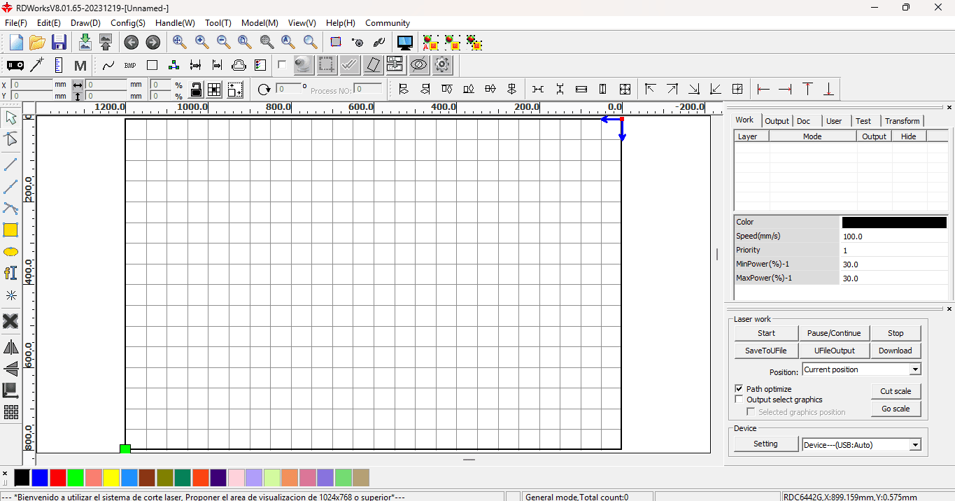
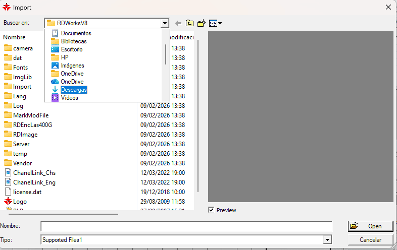
6.1 Importing the DXF File into RDWorks
For the laser cutting process, I used RDWorks to import the DXF file through the File → Import option. After loading the design into the workspace, I checked the scale, position, and orientation of the file to ensure it fit correctly within the laser bed before proceeding with layer assignment and cutting parameter configuration.
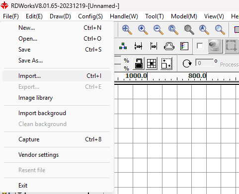
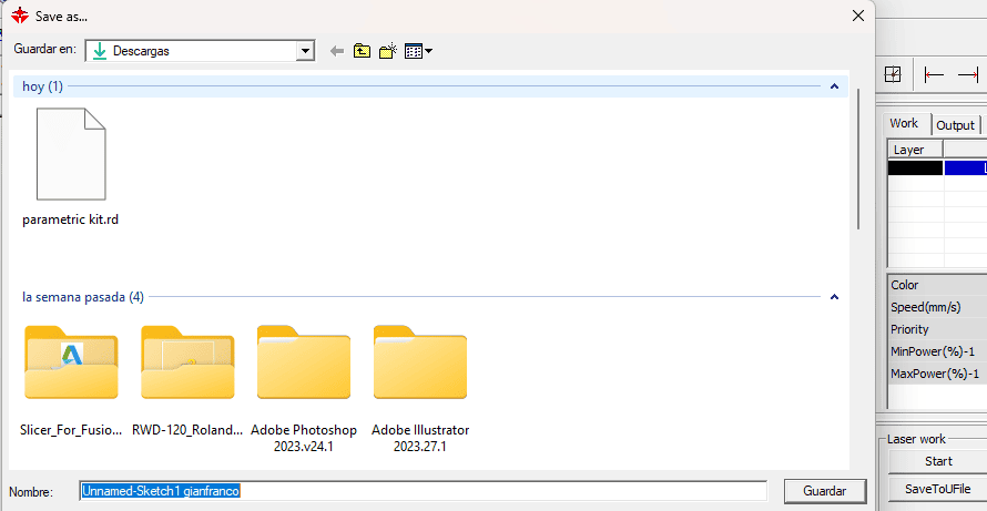
6.2 DXF File Import from your favorite Folder
To import the design into RDWorks, I used the Import option and selected the DXF file from the Downloads folder. Once the file was loaded into the software, it appeared in the workspace, allowing me to verify the file before continuing with the laser cutting setup.
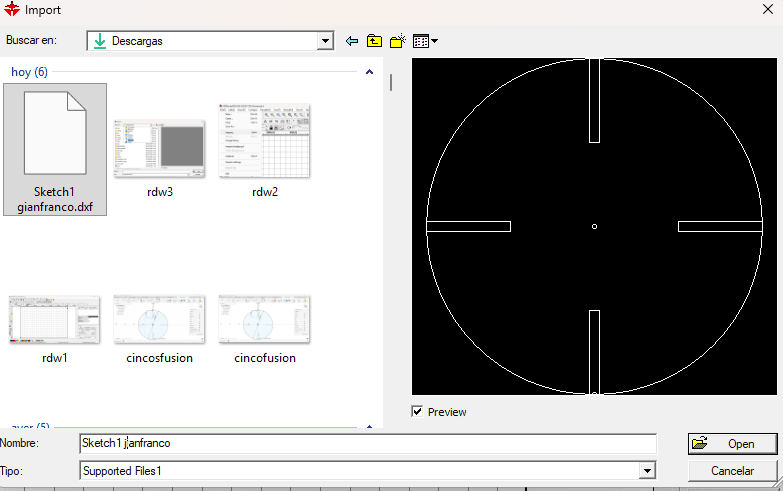
6.3 DXF File Selection and Preview in RDWorks
After accessing the Downloads folder, I selected the DXF file to be used for laser cutting. RDWorks displayed a preview of the design, allowing me to confirm that the geometry, scale, and orientation were correct before opening the file. This verification step ensured that the correct design was imported and ready for further configuration in the laser cutting workflow.
6.4 DXF Layout and Layer Configuration in RDWorks
Once the DXF file was imported into RDWorks, the design was arranged within the working area of the laser bed, duplicating the parts to optimize material usage. The elements were assigned to a Laser Cut layer with Output enabled, and the cutting parameters were configured, including speed and laser power values. The grid view helped verify alignment, spacing, and scale, ensuring that all parts were correctly positioned and ready for fabrication before starting the laser cutting process.
6.5 DXF Layout and Layer Configuration in RDWorks
Once the DXF file was imported into RDWorks, the design was arranged within the working area of the laser bed, duplicating the parts to optimize material usage. The elements were assigned to a Laser Cut layer with Output enabled, and the cutting parameters were configured, including speed and laser power values. The grid view helped verify alignment, spacing, and scale, ensuring that all parts were correctly positioned and ready for fabrication before starting the laser cutting process.
6.6 Save your file
Once the DXF file was imported into RDWorks, the design was arranged within the working area of the laser bed, duplicating the parts to optimize material usage. The elements were assigned to a Laser Cut layer with Output enabled, and the cutting parameters were configured, including speed and laser power values. The grid view helped verify alignment, spacing, and scale, ensuring that all parts were correctly positioned and ready for fabrication before starting the laser cutting process.
7. Preparing the cut
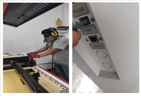
Once the file was saved on the USB drive, I moved to the laser cutting machine and inserted the USB into the corresponding port. This step allowed the machine to access the prepared file and ensured that the design was ready to be selected and executed directly from the laser cutter interface.
7.1 Loading the Cutting File from USB
After inserting the USB drive into the laser cutting machine, I accessed the control panel to locate and select the cutting file. Using the navigation buttons, the file was loaded directly from the USB, and the machine interface displayed key information such as file name, coordinates, speed, and power settings. This step allowed me to confirm that the correct file was selected and that the machine was properly prepared before starting the laser cutting process.
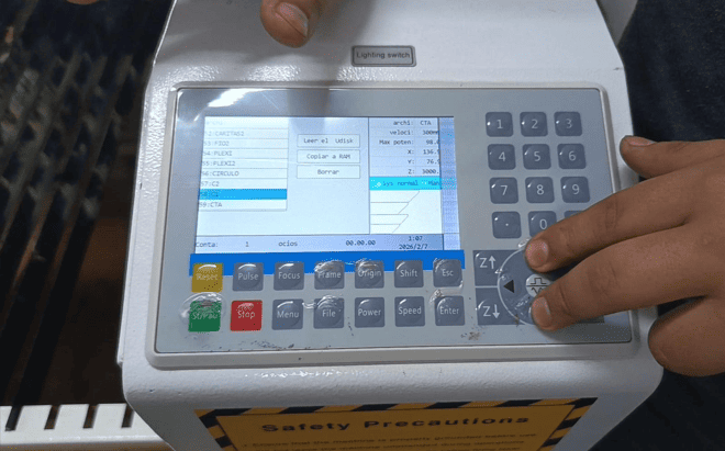
7.2 Selection of the file to be cut
Then I proceed to look for the file I cloned in the machine's local memory, once I find it I select it by pressing the Enter button
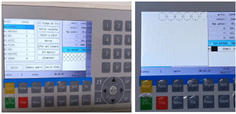
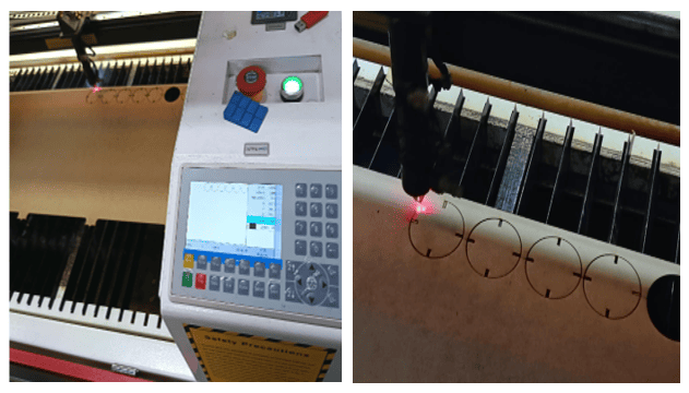
7.3 Vectorial Cutting Setup and Execution
The images show the laser cutting machine during the setup and cutting process. After selecting the file on the control panel, the material was placed on the laser bed and the laser head was positioned at the starting point. A frame test was performed to verify the cutting area and ensure proper alignment. Once everything was confirmed, the cutting process was started, and the laser head followed the programmed paths to cut the designed shapes accurately.
8.Raster cutting
In this step, I imported my design into RDWorks and organized all the pieces within the working area of the laser bed. I arranged the circular components with slot joints in a grid layout to optimize the use of the material and ensure efficient cutting. Each piece appears in red, indicating that it is assigned to a cutting layer. On the right panel, I configured the laser parameters, setting the mode to “Cut” and adjusting values such as speed and power according to the material. This step allowed me to verify the position, scale, and duplication of the parts before proceeding with the fabrication process.
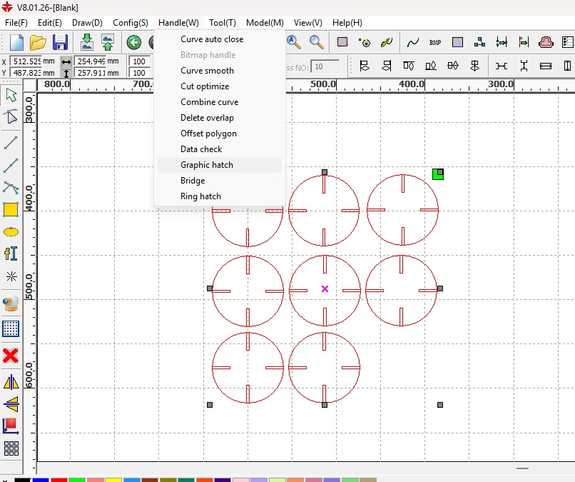
8.1Applying Raster (Hatch)
In this step, I explored the raster engraving configuration by accessing the “Handle” menu in RDWorks and selecting the “Graphic hatch” option. This tool allows me to define how the laser will fill or engrave areas instead of just following vector paths. While my design is primarily focused on cutting, this option is useful when I want to add engraved details, textures, or patterns inside the shapes. By opening this menu, I can control parameters related to fill style, spacing, and engraving direction, which directly affect the visual result on the material. This step helped me understand the difference between vector cutting and raster engraving, and how both processes can be combined in a single design to enhance functionality and aesthetics.
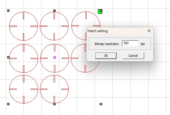
8.2 Configuring Raster Resolution
In this step, I configured the raster engraving settings by adjusting the hatch resolution in RDWorks. A window appears where I set the bitmap resolution to 300 dpi, which defines the level of detail for the engraving process. A higher DPI value results in finer detail and smoother engraving, but it also increases the processing time. Since I wanted a good balance between quality and efficiency, I selected 300 dpi as an optimal value. This configuration is important when working with raster engraving because it directly affects how detailed and clean the final engraved result will appear on the material.
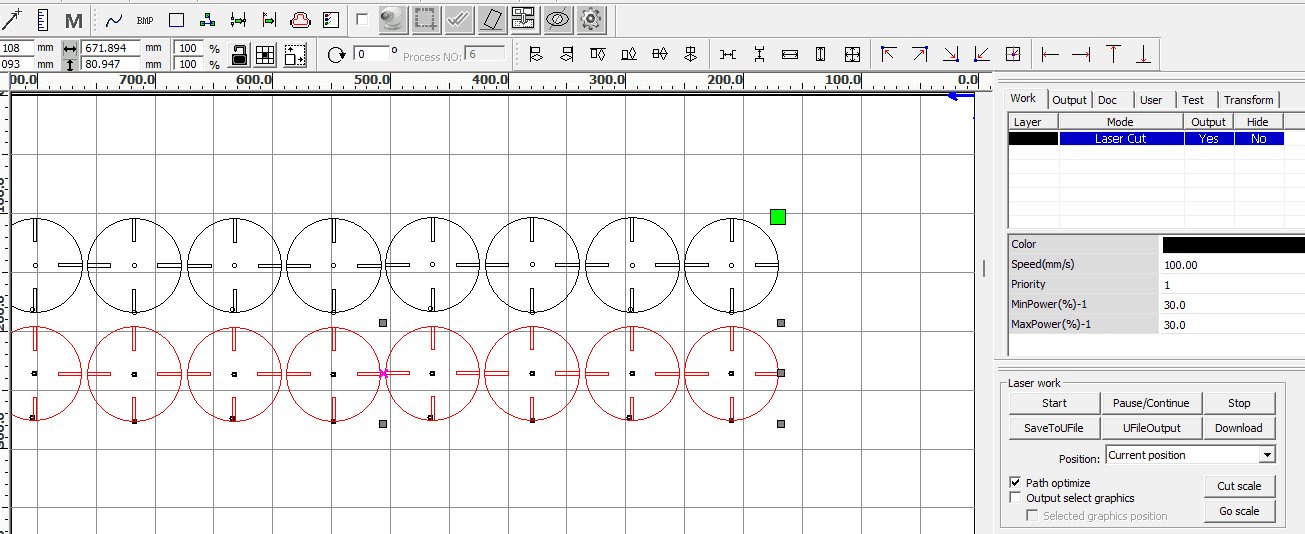
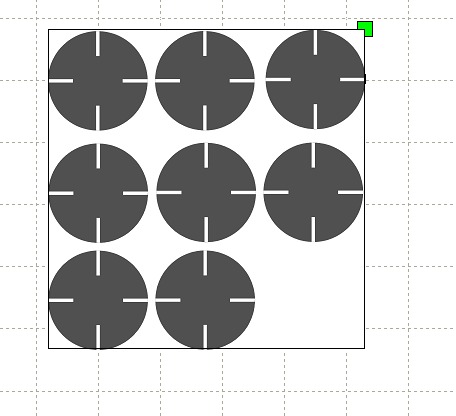
8.3 Raster Engraving Pattern Analysis
The image displays a geometric composition organized within a square frame over a design grid, Each circle features a distinctive central cross detail defined by four white linear segments that do not meet at the center, suggesting a reference point for machining or laser engraving processes. The layout shows precise alignment with the axes of the work plane, and a green selection node is visible at the top-right corner of the main container, indicating that the set is being treated as a vector object or an active region of interest for digital processing.
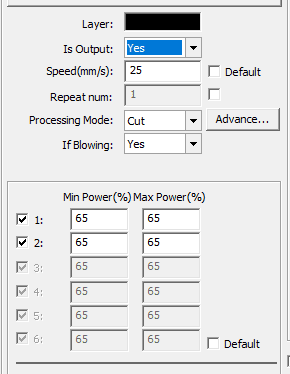
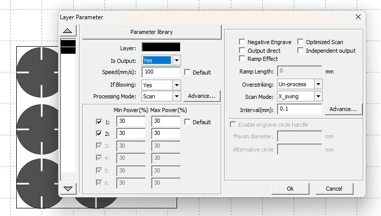
8.4 Laser Software Parameter Configuration
The image displays a "Layer Parameter" settings window from a laser control software , detailing the technical specifications for the raster engraving task. The configuration is set to a "Scan" processing mode with a travel speed of 100 mm/s and a constant power output of 30% (both minimum and maximum) across the active laser tubes. Key operational details include an enabled air assist ("If Blowing: Yes"), a scan interval of 0.1 mm for line density, and a "X_swing" scan mode, which indicates the laser head will move bi-directionally along the X-axis to fill the circular shapes. These settings represent the bridge between the digital design and the physical execution, determining the depth, darkness, and overall resolution of the final engraved pattern on the material.
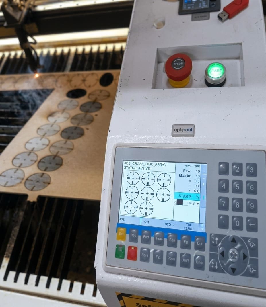
8.5 Raster Cutting Final Result
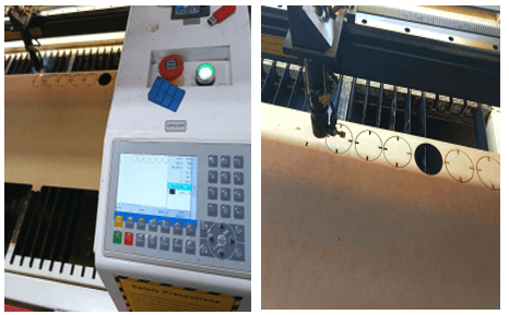
This image captures the physical execution stage of the project, showing the CO2 laser machine's control panel and the workbed in action. The digital interface on the machine's display confirms the job "Jian Raster" is currently ACTIVE, matching the pattern previously configured in the software. On the left, we can see the laser head actively engraving the circular shapes onto a wooden or MDF sheet, with visible smoke and several completed rows already processed. The illuminated green "START" button and the emergency "STOP" button on the control unit emphasize the transition from digital parameters to hardware manufacturing, where the previously set 100 mm/s speed and 30% power are now being applied to create the physical cross-detailed discs.
⚙️ Vector Cutting vs Raster Cutting 🔥
| 🧩 Feature | ✂️ Vector Cutting | 🖨️ Raster Cutting (Engraving) |
|---|---|---|
| 📌 Definition | Follows paths and lines to cut through the material. | Scans line by line to engrave surfaces. |
| ⚙️ Movement | Moves along defined vector paths. | Moves like a printer (left to right). |
| 🔥 Laser Use | High power to cut completely. | Lower power to burn/engrave surface. |
| 🎯 Purpose | Create shapes and separate parts. | Add images, textures, or details. |
| 📐 File Type | Vector files (DXF, SVG, AI). | Bitmap or image files (JPG, PNG). |
| ⏱️ Speed | Faster (only follows lines). | Slower (covers full area). |
| ✨ Result | Clean cuts through material. | Surface engraving with shades. |
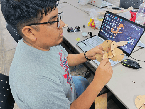
9. Assembly of the Parametric Kit
Once the pieces were laser cut using the required parameters, I began the assembly process based on the original design idea. The main concept was to assemble the parts in the form of a cell phone stand, allowing the parametric kit to have a functional and practical use. This step helped validate the design, confirming that the parts fit correctly and that the parametric approach allowed flexible and reusable configurations.
10. Testing and Validation of the Parametric Kit
Once the parametric kit was fully assembled, I evaluated the material resistance and structural stability under real use conditions. The structure was tested by placing a phone on the stand to observe its behavior, checking for deformation, looseness, or instability. The joints and connections were also reviewed to ensure a proper fit and rigidity. After confirming that the kit could support the intended load and function correctly without structural issues, the design was validated and marked as successful.
.png)
11. Bringing a Machine Back to Life(Vinil Cuttin)
This image shows a Roland cutting machine that I was able to recover from the storage area of unused equipment. The machine was planned to be discarded after several months because its drivers were not compatible with Windows 11 and the original cables were missing. As part of my Fab Academy journey, I decided to take on the challenge of bringing this machine back to life by researching and sourcing the necessary drivers, software, and cables. Through this process, I successfully restored the machine to working condition, allowing it to become a valuable tool that now accompanies me throughout this Fab Academy experience.
11.1 From Recovery to Production
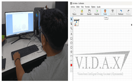
The images show the setup and use of the recovered Roland cutting machine during the Fab Academy process. After successfully restoring the machine, it was connected to a computer and configured with the appropriate software and drivers. On the screen, the VIDAX project design can be seen prepared in the vector workspace, ready for vinyl cutting. This step demonstrates how the rescued machine was fully integrated back into the digital fabrication workflow, allowing me to produce graphics and components related to my final project and confirming the value of restoring unused equipment for active use in Fab Academy.
11.2 Roland GX-24 Calibration and Blade Force Adjustment
The images show the configuration process of the Roland GX-24 vinyl cutter. After several initial cutting attempts that did not produce correct results, the machine settings were adjusted to improve performance. Through testing and iteration, the blade force was set to 80, which allowed the vinyl to be cut properly without damaging the material or backing. This adjustment was key to achieving clean and accurate cuts, demonstrating the importance of parameter testing and calibration when working with digital fabrication machines..

11.3 Final Vinyl Cutting Result
Once the cutting process started and the defined parameters were applied, the machine proceeded to cut the vinyl material correctly. With the blade force properly configured, the Roland GX-24 produced clean and precise cuts, resulting in the V.I.D.A.X logo being successfully fabricated. This confirmed that the selected settings were appropriate and that the machine was correctly calibrated for the task.

11.4 Vinyl Post-Processing: Transfer Application
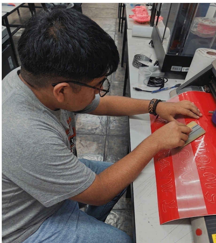
This image documents the importand post-processing stage of vinyl fabrication, specifically focusing on the application of translucent transfer tape over the weeded red vinyl design. The use of a translucent material is essential as it provides the operator with clear visibility of the cut alignment, ensuring that the graphic is picked up precisely without disturbing the original spacing or orientation of the letters. By utilizing a squeegee to apply firm, even pressure, the transfer tape creates a temporary bond with the vinyl, allowing the entire complex design to be lifted from its backing and prepared for seamless final application onto the target surface.
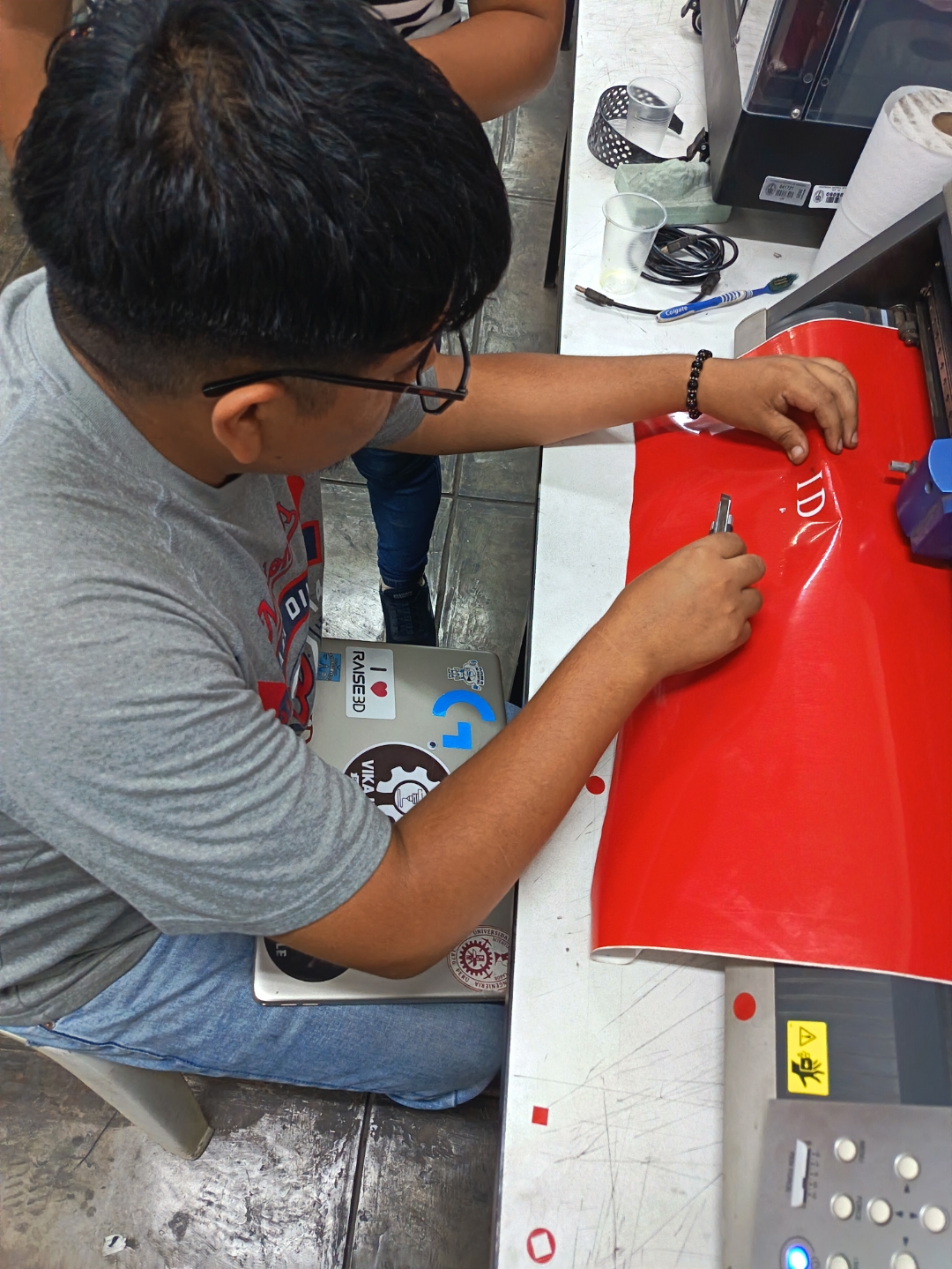
11.5 Vinyl Post-Processing: Precision Removal with Cutting Tools
This image captures another vital aspect of vinyl post-processing, specifically known as weeding, but this time for highly detailed or delicate elements. While larger, standard lettering might be peeled using standard techniques, the operator here is utilizing a precision cutter/scalpel tool (also called a weeding knife) to carefully extract intricate graphics from the red vinyl. The technique seen here demonstrates how the small blade is used to 'catch' and remove individual characters (as seen with the completed 'D' and 'I' already removed), rather than lifting the whole matrix at once. This approach is necessary when the negative space is very fine, to prevent stretching or tearing the intended graphic, and showcases the meticulous manual work required to finalize the complex patterns previously set during the initial design phase.
🧵 Vinyl Cutting Post-Processing Comparison ✂️
| 🧩 Feature | 🔪 Manual Weeding (Cutter) | 📦 Transfer Tape Method |
|---|---|---|
| 📌 Definition | Removing excess vinyl manually using a cutter or hook tool. | Using adhesive tape to lift and transfer the design. |
| 🛠️ Tools | Cutter, weeding tool, tweezers. | Transfer tape, scraper or card. |
| 🎯 Precision | High precision for small details. | Good for maintaining alignment of full designs. |
| ⏱️ Time | Slower, especially for complex designs. | Faster for medium and large graphics. |
| ⚠️ Risk | Risk of damaging small elements. | Risk of bubbles or misalignment during transfer. |
| ✨ Best Use | Fine details, logos, intricate patterns. | Text, large stickers, multi-element designs. |
| 📊 Workflow | Cut → Weed manually → Apply | Cut → Weed → Apply tape → Transfer |
| 💡 Result | Direct control over each element. | Clean and uniform transfer of full design. |
12. Final Reflectiont
This process allowed me to better understand the complete digital fabrication workflow, from design and file preparation to machine setup, testing, and final production. Working with different tools and machines helped me appreciate the importance of iteration, calibration, and problem-solving, especially when initial results were not successful.
Recovering and restoring the Roland machine was a meaningful experience, as it showed how knowledge and persistence can give new life to unused equipment. Overall, this assignment strengthened my technical skills and reinforced the Fab Academy mindset of learning by doing, experimenting, and improving through hands-on experience.

Cleaning what we made

Files
Here are the project files available for download:
- CutStudio for Vinil Cuttin: Download .cst
- RD WORKS File: Download .rd
- Dxf File: Download .dxf
- Fusion 360 File: Download Fusion
What’s coming next week?
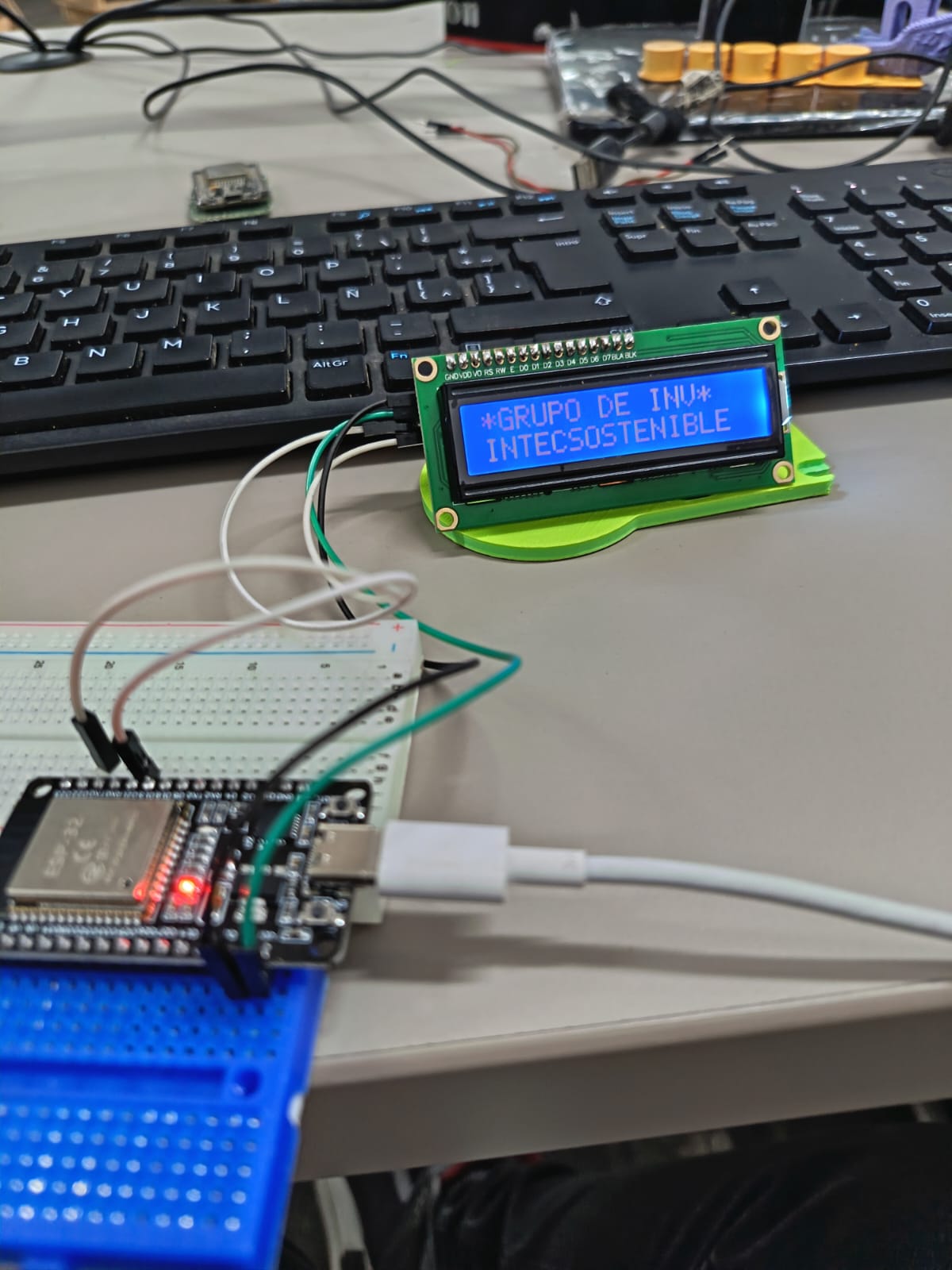
Next week will focus on Embedded Programming, an essential topic for adding intelligence and control to digital fabrication projects. We will work mainly with ESP32-S3 microcontrollers, exploring how to program them to interact with different electronic components.
The week will involve learning how to configure inputs and outputs, control sensors and actuators, and establish communication between hardware and software. By programming the ESP32-S3, we will better understand how embedded systems operate and how code directly influences the behavior of physical devices.
This topic will be especially important for future integration into my final project, as embedded programming will enable automation, data processing, and real-time interaction between components.