Week 02
Computer-Aided Design
Assignment:
This week’s task focused on developing the digital models of my final project, including 2D and 3D design, basic rendering, and visualization of the system. I also optimized images and videos to reduce file size and documented the entire process on my Fab Academy class page.
Week 02 Tasks
- I. Assignment Introduction ✅
- II. Software & Tools ✅
- III. Raster Graphics ✅
- IV. Vector Graphics ✅
- V. CAD Modeling ✅
- VI. Compressing Videos & Images ✅
- VII. Project Files ✅
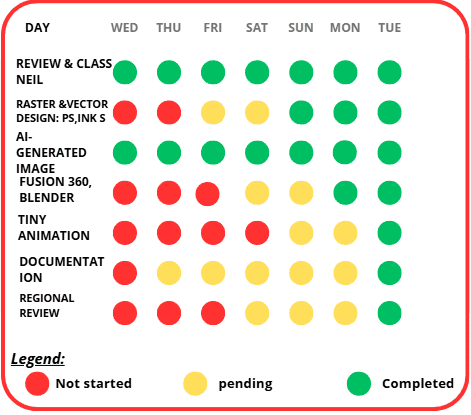
Plan of the week
The weekly plan shows the progress of tasks from Wednesday to Tuesday, using colors to track their status: red for not started, yellow for pending, and green for completed.
At the beginning of the week, most activities were not started. As the days passed, they moved from red to yellow, and finally to green by Monday and Tuesday. Tasks like Review & Class and AI-generated image were completed throughout the week, while others such as Tiny Animation, Documentation, and Regional Review were finished at the end.
Overall, the plan shows a strong improvement during the week, with all tasks completed before the deadline.
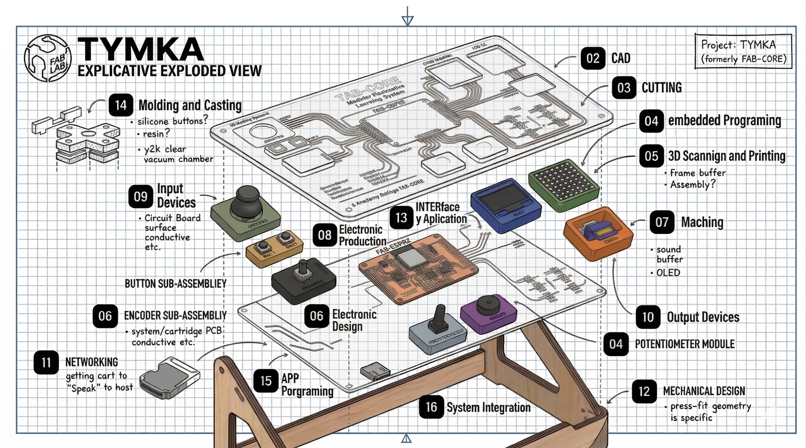
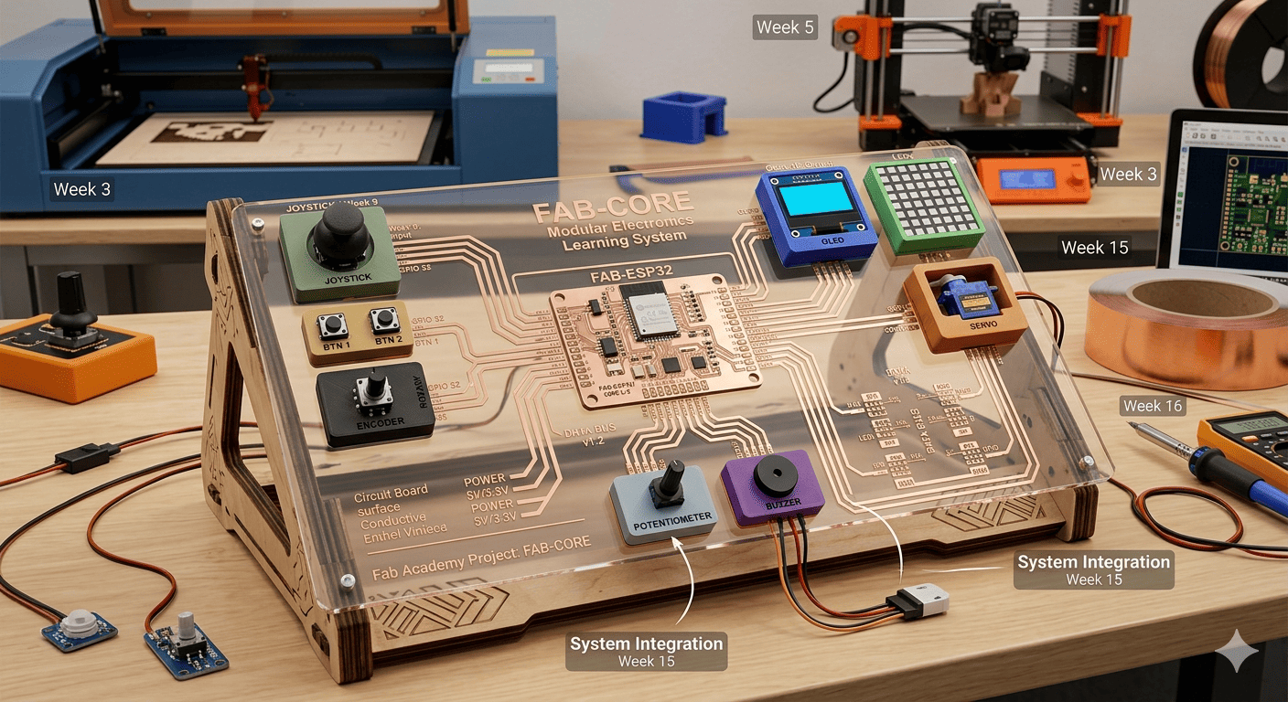
1. C3D model of a possible final project proposal
The image presents a possible final project for Fab Academy called FAB-CORE, a modular electronics learning platform built around an ESP32-based central board. The system integrates multiple input and output modules such as a joystick, buttons, encoder, potentiometer, buzzer, OLED display, LED matrix, and a servo motor, all connected through a clearly designed circuit layout. The transparent top panel allows users to visualize the signal paths, making it both an educational and functional tool for understanding electronics, embedded programming, and system integration.
This project demonstrates a complete digital fabrication workflow, including PCB design and production, 3D printing, laser cutting, electronics integration, and embedded programming. Each module represents different weekly assignments (input devices, output devices, networking, interface design), culminating in a fully integrated system. As a final project proposal, FAB-CORE highlights the development of a scalable and interactive platform that simplifies learning by combining all essential Fab Academy concepts into a single, cohesive device.
>
2. Preview final project proposal
VEO Gemini Pro generate this video using this prompt:
Generate a cinematic video preview of my project, as if it were for a marketing style, so that the student can approach the project and start using it.
1.3 Introduction:
This week was focused on exploring different digital tools to visualize and refine my final project. It became a space for experimentation, where I worked with raster and vector design, 3D modeling, and basic visualization to better define my ideas.
I also rethought the approach to my project, making it more functional and accessible while keeping digital fabrication in mind. Moving from simple sketches to digital models helped me shape the concept, and switching between different tools allowed me to find the workflow that best fits my design process.
2.1 2D Raster
To begin this activity, I first researched the concept of raster in order to better understand the objective of the task. Through this, I learned that raster refers to a method of creating two-dimensional images using pixels. Based on this understanding, I realized that raster images can be used to generate lines and polylines, and they can also be converted into vector formats for further processing.
With this knowledge, I proceeded to work with two different software tools, Photoshop and GIMP, allowing me to explore their functionalities and compare their advantages and limitations.
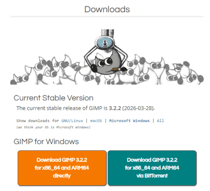
2.2 GIMP GNU IMAGE MANIPULATION PROGRAM
This image shows the download page of GIMP, specifically highlighting the latest stable version available for Windows. GIMP is an open-source image editing tool widely used for raster graphics processing, offering features such as image manipulation, color correction, and basic design capabilities. In this step, I prepared the software environment by downloading and installing GIMP to begin working with raster images.
As part of this activity, I will perform a comparison (versus) between GIMP and Adobe Photoshop, analyzing their differences in usability, tools, performance, and overall workflow for raster image processing. This will help identify the strengths and limitations of each software in the context of digital fabrication and design.
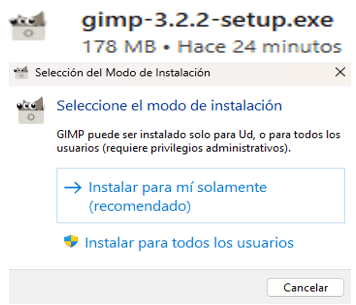
2.3 GIMP Installation Setup
This image shows the installation mode selection of GIMP, where I chose the recommended option to install the software only for my user, allowing a quick and simple setup. This step ensures the program is ready to use and prepares the environment for working with raster images, which will later be compared with Adobe Photoshop.
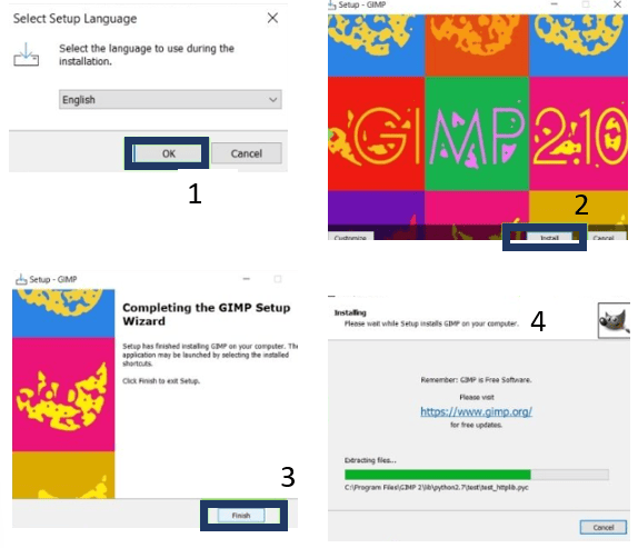
2.4 GIMP Installation Process
This image shows the final steps of the installation process of GIMP, including language selection, installation progress, and setup completion. During this stage, I confirmed the configuration settings and allowed the software to install properly on my system.
Once the installation was completed, the program was ready to use for raster image editing. This ensured that I could begin working with image processing tasks and later compare its performance and features with Adobe Photoshop.
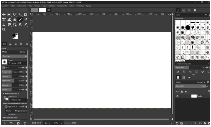
2.5 GIMP Interface Overview
This image shows the main interface of GIMP after installation. The workspace includes essential tools such as the toolbox on the left, brush and tool settings, and panels for layers and filters on the right. This layout allows efficient access to different image editing functions and helps organize the workflow when working with raster graphics.
At this stage, I explored the interface to understand how each tool works and how to navigate the environment. This familiarization is important to begin editing images effectively and to later compare the usability and workflow of Adobe Photoshop.
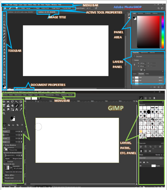
2.6 Interface Comparison: Photoshop vs GIMP
This image compares the interface of Adobe Photoshop (top) and GIMP (bottom). Both programs share a similar structure, including a top menu bar, a toolbar on the left, and panels on the right for layers and properties. However, Photoshop presents a more organized and visually structured layout, with clearly defined sections such as the properties panel and document settings, making navigation more intuitive for users.
On the other hand, GIMP offers a flexible but slightly less structured interface, where tools and panels are also accessible but may require more familiarization. While both software provide the essential tools for raster image editing, Photoshop stands out for its user-friendly design and workflow optimization, whereas GIMP provides a powerful open-source alternative with customizable features.
2.7 Photoshop vs GIMP: Image Enhancement Comparison
The images compare the process of improving a hand-drawn circuit sketch in Adobe Photoshop (top) and GIMP (bottom). In both cases, the goal is to enhance clarity, adjust resolution, and refine details for digital fabrication. Photoshop shows a more streamlined workflow, with tools like selection and image size adjustment easily accessible, allowing faster and more precise improvements.
In contrast, GIMP requires more steps to achieve similar results, and the final image quality is not as refined. Based on this comparison, Photoshop is more efficient and user-friendly for image enhancement, especially when preparing sketches for fabrication processes, as it reduces time and complexity while delivering better results.
.png)
⚔️ Photoshop vs GIMP Comparison
| 🧩 Feature | 🎨 Photoshop | 🐧 GIMP |
|---|---|---|
| 💻 Interface | Clean, professional, well-organized | Flexible but less structured |
| 🧰 Tools | Advanced and industry-standard tools | Complete tools but slightly less refined |
| ⚙️ Customization | Moderate customization | Highly customizable (open-source) |
| 🚀 Performance | Optimized and smooth workflow | Good performance, depends on setup |
| 💰 Cost | Paid subscription | Free and open-source |
| 📚 Learning Curve | Easier for beginners (intuitive UI) | Takes time to get used to |
| 🔄 Workflow | Professional and efficient | Functional but less optimized |
3. 2D Vector
Continuing with my workflow, I explored vector design to better understand the difference between raster and vector graphics. While raster images are composed of pixels, vector graphics are created using lines and paths, allowing greater scalability and precision. This helped me connect the concepts I previously worked on in raster editing with new design possibilities.
In my case, I had experience using other design software, but for this assignment I decided to experiment with Inkscape to expand my knowledge and compare tools, similar to what I did with GIMP and Adobe Photoshop. Understanding these fundamentals is important, as it builds a strong base for more advanced topics such as digital fabrication and 3D modeling.
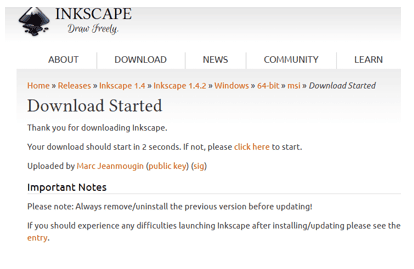
3.1 Inkscape's Path-Artist's
This image shows the download page of Inkscape, highlighting the latest stable version available for installation. Inkscape is an open-source vector graphics editor widely used for creating scalable designs based on paths and lines, offering tools for drawing, editing, and exporting vector files. In this step, I prepared the software environment by downloading and installing Inkscape to begin working with vector graphics.
As part of this activity, I will perform a comparison (versus) between Inkscape and Adobe Illustrator, analyzing their differences in usability, tools, performance, and overall workflow for vector design. This will help identify the strengths and limitations of each software in the context of digital fabrication and design.
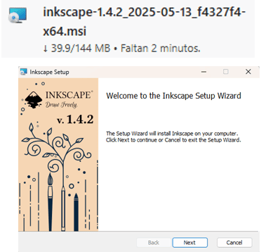
3.2 Inkscape Installation Setup
This image shows the installation setup of Inkscape, where I selected the recommended configuration to complete the process quickly and efficiently. This step ensures that the software is properly installed and ready to be used for vector design tasks.
Preparing the environment in this way allows me to start working with scalable graphics and continue the workflow, which will later be compared with Adobe Illustrator to evaluate differences in usability and performance.
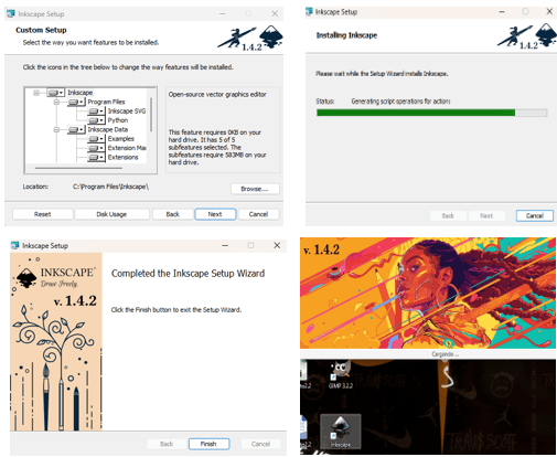
3.3 Inkscape Installation Process:
This image shows the final steps of the installation process of Inkscape, including configuration confirmation, installation progress, and completion. During this stage, I verified that all settings were correctly applied to ensure a proper installation on my system.
Once the installation was completed, the software was ready to use for vector design tasks. This allowed me to start creating scalable graphics and later compare its performance and features with Adobe Illustrator.
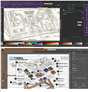
3.4 Adobe Illustrator vs Inkscape: Image Enhancement Comparison
This image compares the image enhancement capabilities of Adobe Illustrator and Inkscape. Both programs allow users to improve and refine graphics through vector-based adjustments such as path editing, color modification, and scaling without loss of quality. Illustrator provides more advanced and precise tools for image enhancement, offering better control over gradients, effects, and alignment, which results in a more refined and professional output.
In contrast, Inkscape also offers essential tools for enhancing vector images, including node editing, filters, and color adjustments. While it may not be as optimized or polished as Illustrator, it still allows effective image improvements and supports a wide range of design needs. This comparison highlights how both tools can be used for similar purposes, but with differences in workflow efficiency and level of control.
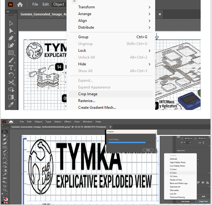
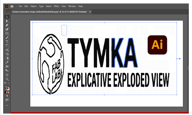
3.5 Vector Editing and Design Process
In this stage, I worked on vector editing using design tools to refine and prepare my project graphics. As shown in the image, I used options such as grouping, alignment, and cropping to organize different elements within the design. These tools allowed me to manage complex compositions more efficiently, especially when working with multiple shapes and text elements.
Additionally, I designed my logo by myself using Adobe Illustrator, since it performed better on my laptop and provided a smoother workflow. When I tried using Inkscape, my system experienced crashes, which limited my progress. Illustrator allowed me to continue working without interruptions, making it the best option for my design process. 🎨⚙️ control.
⚔️ Adobe Illustrator vs Inkscape
| 🧩 Feature | 🎨 Adobe Illustrator | 🐧 Inkscape |
|---|---|---|
| 💻 Interface | Clean, professional, well-structured | Flexible but less organized |
| 🧰 Tools | Advanced, industry-standard tools | Complete tools, slightly less refined |
| ⚙️ Customization | Moderate customization | Highly customizable (open-source) |
| 🚀 Performance | Smooth and optimized workflow | Good performance, may vary by system |
| 🎯 Precision | High precision and control | Good precision with manual adjustments |
| 💰 Cost | Paid subscription | Free and open-source |
| 📚 Learning Curve | More intuitive for beginners | Requires more practice |
| 🔄 Workflow | Professional and efficient | Functional but less optimized |
4.1 3D Design
In this stage, I explored 3D design to expand from 2D workflows into three-dimensional modeling. This involves creating digital objects with volume, geometry, and spatial properties, which are essential for prototyping and digital fabrication. Understanding 3D design allows better visualization, simulation, and preparation of models for manufacturing processes such as 3D printing or CNC machining.
For this purpose, I worked with Autodesk Fusion 360 and Blender to compare their capabilities. Fusion 360 is focused on parametric and engineering design, offering precise tools for modeling functional parts, while Blender is more oriented toward artistic modeling, rendering, and animation. This comparison helped me understand how each software can be applied depending on the project requirements, combining technical accuracy with creative flexibility.
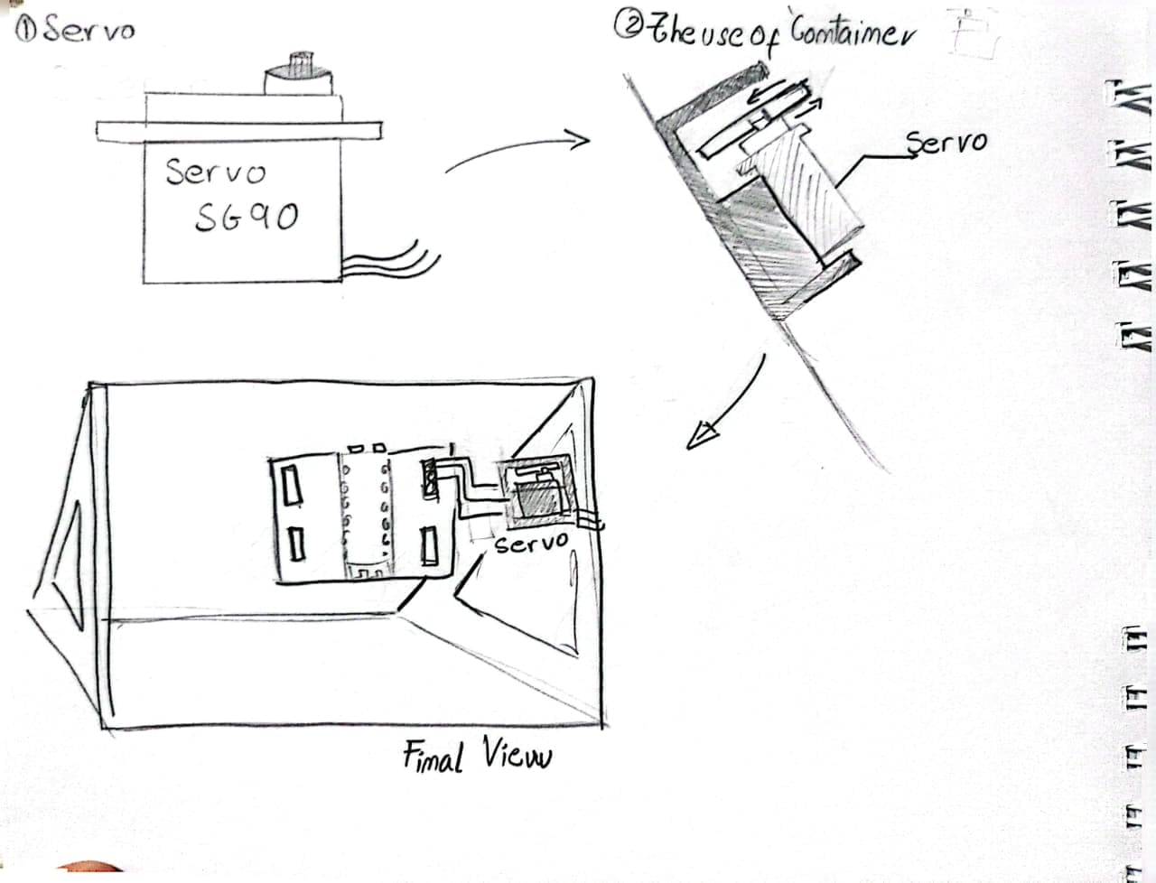
And also this is a sketch of a 3d model component that I need in my project, it is a Servomotor and a container.
4.2 Blender
In this stage, I explored Blender as a tool for 3D design and modeling. Blender is an open-source software widely used for creating 3D models, animations, and visualizations. It provides a wide range of tools for sculpting, rendering, and editing, allowing the creation of complex and detailed geometries.
While working with Blender, I focused on understanding its interface and basic modeling tools to create and manipulate 3D objects. This experience helped me develop skills in spatial design and visualization, which are important for digital fabrication. Compared to more engineering-focused tools, Blender offers greater flexibility for creative modeling and design exploration.
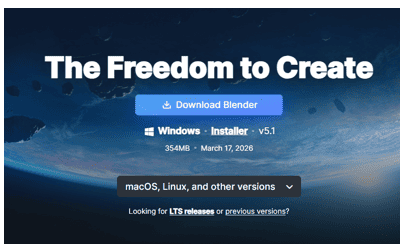
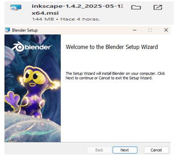
4.3 Blender Installation Setup
This image shows the installation setup of Blender, where I selected the appropriate configuration to complete the installation process efficiently. This step ensures that the software is correctly installed and ready to be used for 3D modeling and design tasks.
Preparing the environment in this way allows me to start working with 3D objects, explore modeling tools, and continue the workflow. This will later support the comparison with Autodesk Fusion 360 to evaluate differences in usability, precision, and design approach.
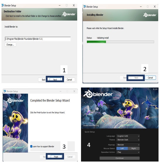
4.4 Blender Installation Process:
This image shows the final steps of the installation process of Blender, including configuration confirmation, installation progress, and completion. During this stage, I verified that all settings were correctly applied to ensure a proper installation on my system.
Once the installation was completed, the software was ready to use for 3D modeling and design tasks. This allowed me to start creating and exploring 3D objects, which will later be compared with Autodesk Fusion 360 to analyze differences in workflow, precision, and functionality.
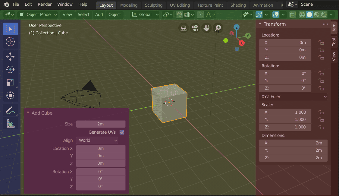
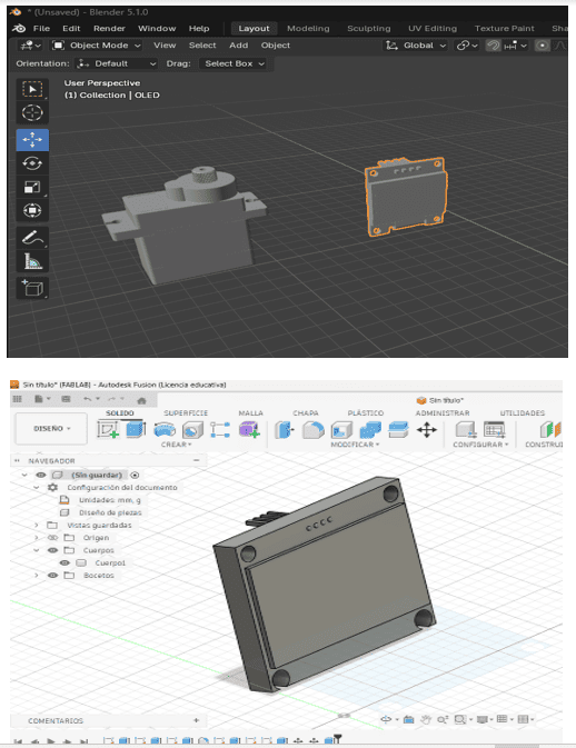
4.5 Blender Interface Overview and Key Panels:
The image shows the interface of Blender in Object Mode, where a default cube is placed in the 3D viewport. The central area displays the workspace grid and the cube, which is currently selected (highlighted in orange). On the left (blue area), the toolbar contains basic transformation tools such as move, rotate, scale, and selection options, allowing the user to interact directly with objects in the scene.
In the lower-left (purple box), the “Add Cube” panel appears, where parameters like size, position, and rotation of the newly created object can be adjusted. On the right side (red area), the Transform panel shows detailed numeric controls for the selected object, including location, rotation, scale, and dimensions. These panels are essential for precise modeling, enabling both manual manipulation in the viewport and exact value input for accurate 3D design.
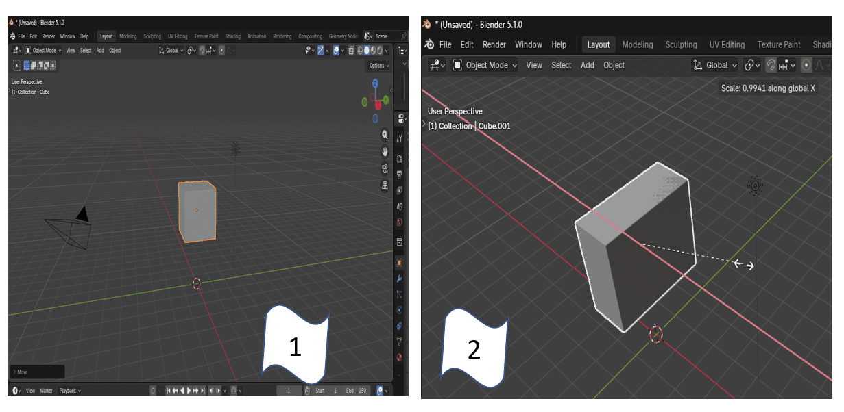
4.6.1 Basic Modeling in Blender (Step 1 & Step 2)
Step 1: Opening Blender and Default Object
In the first step, I opened Blender, where the program automatically provides a default scene that includes a basic geometric object, in this case, a cube. This cube serves as the starting point for most 3D modeling processes, allowing me to begin designing from a simple base shape. In this case, my objective is to model a servo motor, which will be part of my final project as an output component integrated into my training kit.
Step 2: Scaling the Object
In the second step, I modified the size of the cube using the scale function. By pressing the “S” key, I was able to resize the object proportionally. Additionally, I used S + X, S + Y, or S + Z to scale the object along a specific axis depending on my design needs. This allowed me to precisely adjust the dimensions of the model, transforming the initial cube into a more customized shape that will serve as the base structure of the servo motor. 🧊⚙️
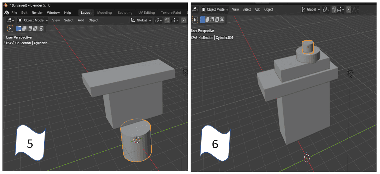
4.6.2 Basic Modeling in Blender (Step 3 & Step 4)
Step 3: Duplicating the Base Object
In this step, after scaling the initial cube into a more rectangular shape, I duplicated the object to build the structure of the servo motor. Using the shortcut Ctrl + C / Ctrl + V, I created a copy of the base geometry, which allowed me to form additional parts of the model more efficiently. This helped me maintain consistent proportions while constructing the main body of the servo. 🧩
Step 4: Adding Cylinders for the Servo Mechanism
Next, I added new geometric elements to represent the functional parts of the servo motor. By using the shortcut Shift + A, I accessed the add menu in Blender and inserted cylinders. These components simulate the area where the servo arms (rotating parts) will be attached, which is essential to demonstrate how an output device works in my final project. After adding the cylinders, I positioned and organized them correctly within the model to match the structure of a real servo motor. This step was important to give both functional meaning and visual clarity to the design, aligning it with the purpose of my training kit project. ⚙️🧊
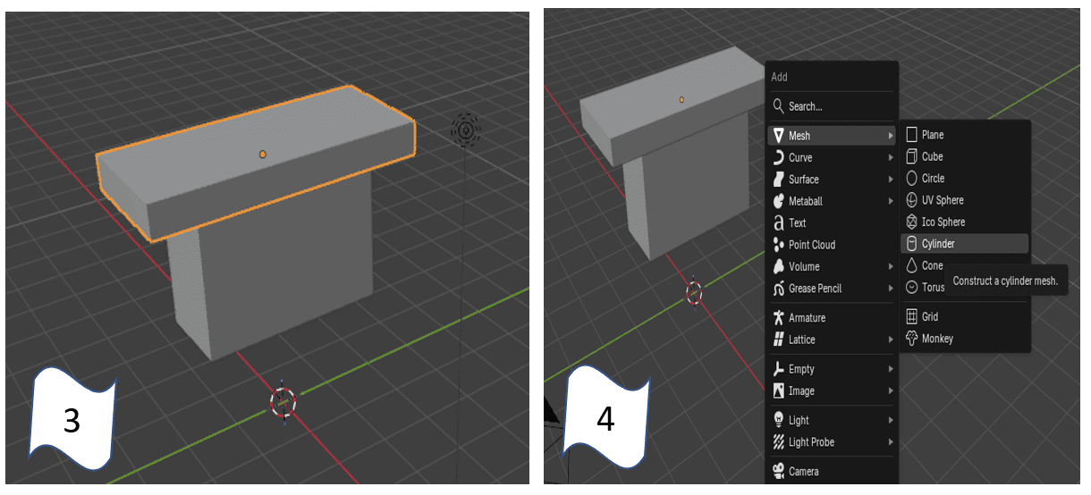
4.6.3 Basic Modeling in Blender (Step 5 & Step 6)
Step 5: Adjusting the Cylinder Shape
In this step, I focused on modifying the cylinder previously added to better match the proportions of a servo motor component. Using scaling and positioning tools in Blender, I adjusted its height and diameter to represent the base where the rotating mechanism will be placed. This step allowed me to refine the geometry and ensure it fits correctly with the rest of the structure. 🧱
Step 6: Assembling the Servo Components
Finally, I positioned the cylinder on top of the main body and added an additional smaller cylinder to represent the servo shaft (the part where the rotating arms are attached). By aligning and organizing these elements, I was able to recreate a simplified structure of a servo motor. This step was essential to visually demonstrate how an output device works, as the upper part represents the axis of rotation that will later simulate movement in my final project. ⚙️🧊
5.Fusion 360 – Understanding Precision & Parametric Modeling
For my pill dispenser with artificial vision project, Fusion 360 played a key role in understanding precision and parametric modeling. By using constraints, parameters, and dimensions, I designed the main structure and internal components, such as pill compartments and supports for electronic elements like the camera and motors.
Parametric modeling allowed me to easily adjust measurements and test different design variations without rebuilding the model from scratch. This was especially important to ensure proper assembly, tolerance control, and compatibility with digital fabrication processes such as 3D printing and CNC machining.
Overall, Fusion 360 helped translate conceptual ideas into a functional and manufacturable design.
Finally, the designs were exported as STL files, preparing the models for fabrication and allowing direct testing of the parts through rapid prototyping.
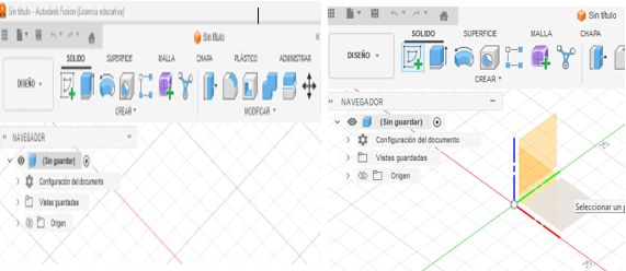
5.2 3D Modeling in Fusion 360 (Step 1 & Step 2)
Step 1: Creating the Sketch
In this step, I opened Autodesk Fusion 360 and started by selecting the sketch tools to define the base geometry of my design. Specifically, I used rectangle tools to create the main shapes, since the servo motor and its container are primarily composed of rectangular structures. This allowed me to establish the foundation of the model in a precise and structured way. In this case, my objective is to model a servo motor along with its housing, which will be part of my final project as an output component integrated into a training kit.
Step 2: Defining Dimensions and Preparing for Extrusion
Next, I began developing the sketch by assigning accurate dimensions to each rectangular section. Using constraints and measurement tools, I ensured that all parts were properly scaled and aligned according to the required proportions. This step is essential because it prepares the design for the next stage, where I will use the extrude tool to convert the 2D sketch into a 3D model. By defining precise measurements, I can guarantee that the final model will be functional and suitable for integration into my project. 📐⚙️
.png)
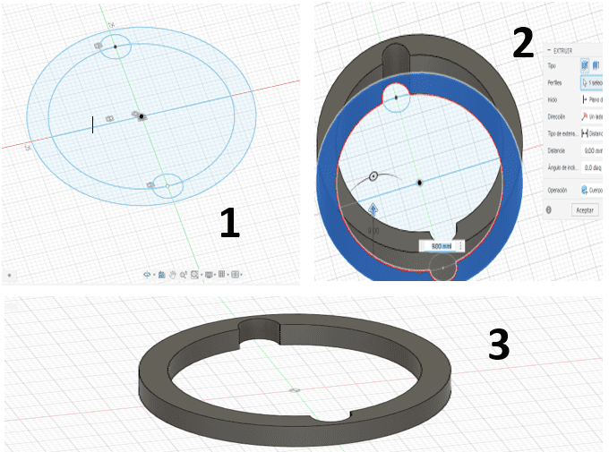
5.2.2 3D Modeling in Fusion 360 (Step 3 & Step 4)
Step 3: Extruding the Sketch into a 3D Volume
In this stage, I used the Extrude tool to give depth to the profiles created in the previous steps. By selecting the closed sketches and setting a distance of 16 mm, I transformed the 2D rectangles into a solid 3D body that represents the main structure of the servo motor and its container. This process is vital for my final project, as it allows me to visualize the real space the component will occupy within the TYMKA Training Kit. This solid block serves as the core housing that will eventually protect the internal mechanics of the output device.
Step 4: Modeling the Output Shaft and Top Cylinders
Finally, I began modeling the top sections of the servo motor by creating new sketches on the upper face of the previously extruded body. I designed the cylindrical parts that function as the output shaft, where the servo horns or blades will be attached. These cylinders are crucial for the actuator's functionality, as they represent the moving parts that will interact with the rest of the kit. By completing these details, I ensure that the servo motor is accurately represented as a functional Output component, ready for integration into my modular system. 🤖🔌
.png)
5.2.3 3D Modeling in Fusion 360 (Step 5 & Step 6)
Step 5: Completing the 3D Model of the Servo Motor
In this step, I finalized the 3D modeling of the servo motor by integrating the output shaft with the servo horn or blades. This completed assembly represents the fully designed actuator, showcasing the precise geometry required for its mechanical movement. As a key Output component for my final project, having the motor fully modeled is essential to ensure that the physical interaction between the motor and the training kit's structure is perfectly aligned. This detailed 3D representation serves as the digital twin of the hardware that will be used in the TYMKA Training Kit.
Step 6: Creating the Enclosure with Plane Offset
Next, I proceeded to design the outer container by using the Offset Plane tool to create a new construction plane at a distance of 10 mm from the motor's side surface. This separation is strategic, as it establishes the necessary clearance for the container walls, ensuring the servo motor fits comfortably within its compartment. By defining this specific offset, I can accurately sketch and extrude the enclosure that will protect the electronic components. This step is crucial for the modularity of my project, as it guarantees that the output module can be easily integrated and secured within the larger training ecosystem. 🛠️📐
.png)
5.2.4 3D Modeling in Fusion 360 (Step 7 & Step 8)
Step 7: Extruding the Enclosure Walls
In this step, I used the Extrude tool to give volume to the enclosure sketch created on the offset plane. By selecting the outer profile and extruding it toward the motor with a distance of -17 mm, I formed the protective walls of the container. This negative value ensures the extrusion goes in the correct direction to surround the motor without overlapping its geometry. This part of the design is fundamental for my final project, as the housing provides a secure mounting structure for the Output component, ensuring the servo motor is properly shielded and stable within the TYMKA Training Kit.
Step 8: Reviewing the Final Integrated Model
Finally, I completed the assembly to achieve the final form of the servo motor integrated within its dedicated container. This 3D model shows the motor perfectly positioned inside the housing, with enough clearance for the mechanical movements of the output shaft and horn. Reaching this stage is a major milestone for my Fab Academy documentation, as it validates that the digital design is ready for fabrication. This final component will now be part of the modular system, representing a functional and professionally housed actuator that is central to the training kit's educational purpose. 📦🦾
.png)
6. Blender vs Fusion 360: Make a model
In this stage, I compared Blender and Autodesk Fusion 360 to understand their differences in 3D modeling. Blender is mainly focused on artistic and organic modeling, offering powerful tools for sculpting, rendering, and creating complex visual designs. On the other hand, Fusion 360 is oriented toward parametric and engineering design, making it more suitable for creating precise and functional components.
Based on my experience, I decided to continue working with Fusion 360, as it better fits the needs of my project. While modeling an OLED I2C display, which is a key component of my system, I noticed that in Blender it took me around 10 minutes to complete the model due to its more artistic workflow. In contrast, using Fusion 360, I was able to create the same model in approximately 2 minutes thanks to its parametric tools and precision. This comparison clearly showed that Fusion 360 is more efficient for mechanical design and prototyping, especially when working with electronic components and structured geometries.
⚔️ Blender vs Fusion 360
| 🧩 Feature | 🎨 Blender | ⚙️ Fusion 360 |
|---|---|---|
| 💻 Interface | Flexible but complex | Clean and engineering-oriented |
| 🧰 Modeling Type | Organic and artistic modeling | Parametric and precise modeling |
| 🎯 Precision | Moderate precision | High precision (ideal for engineering) |
| 🚀 Workflow | Creative but slower for technical parts | Fast and efficient for mechanical design |
| ⏱️ Modeling Time | ~10 minutes (OLED model) | ~2 minutes (same model) |
| ⚙️ Use Case | Animation, rendering, artistic design | Engineering, prototyping, fabrication |
| 💰 Cost | Free and open-source | Free (students) / Paid license |
| 📚 Learning Curve | Steeper (many tools) | Easier for technical workflows |
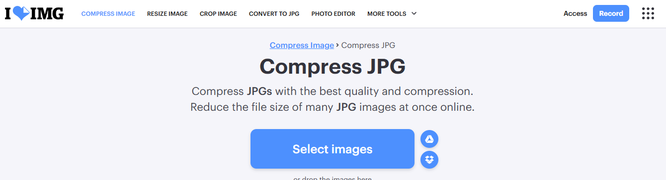
7.IMAGE COMPRESSOR
To optimize the images for my Fab Academy website, I used the online tool iLoveIMG This platform allowed me to easily compress my images without losing too much quality, which is important to keep the website fast and lightweight.
By reducing the file size, my web pages load faster and are easier to upload to GitLab. This also helps keep the repository organized and prevents heavy files from slowing down the site. The tool was simple to use and very effective for preparing images for web documentation.
8.AI-Generated Images – Speeding Up the Process
Curious about how AI could speed up my design process, I decided to test AI-generated images to explore different visual concepts for my final project in this case I used Gemini AI. This allowed me to quickly visualize ideas, experiment with styles, and refine the overall look before moving into detailed modeling and fabrication.
To guide the AI, I used the following prompt:
> “Professional product photo of a "FAB-CORE Modular Electronics Learning System." An angled clear acrylic panel is mounted on a laser-cut wooden base, showcasing intricate etched copper circuits and colorful modular components (joystick, buttons, OLED screen, servo, and LED matrix). Set on a Fab Lab workbench with an industrial blue laser cutter and a 3D printer visible in the background, labeled with "Week 3" and "Week 5" text. High-resolution engineering style with clean studio lighting, tools like a multimeter and soldering iron are on the sides.”This helped me transform my original sketch into a more polished and artistic version, which I later used as visual reference for the next stages of the design process.
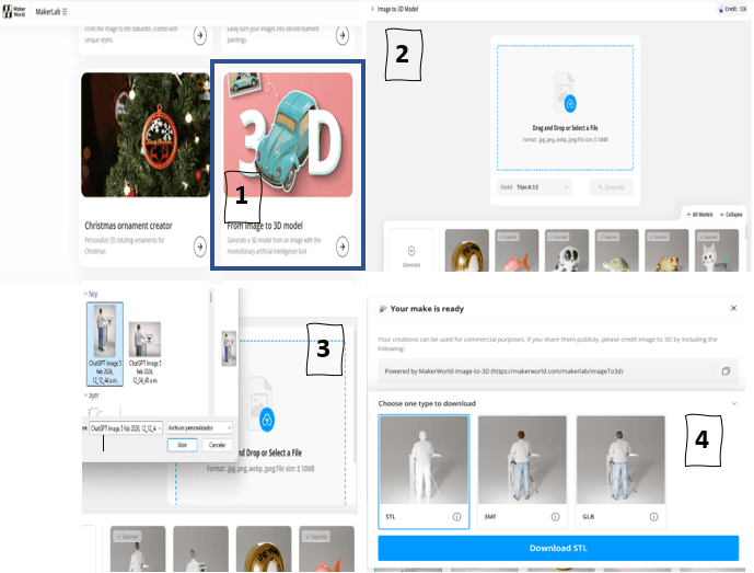
9.Image to 3D Model
To achieve a more realistic representation of my pill dispenser with artificial vision, I used ChatGPT to generate a realistic image based on a hand-drawn sketch of the project. This step helped me better visualize proportions, details, and the overall form of the device before moving into 3D modelin
Once the realistic image was generated, I used the MakerWorld platform, which provides an image-to-3D model feature. This tool allowed me to convert the generated image into a basic 3D model, serving as a starting point for further refinement.
>This workflow helped bridge the gap between concept sketches and 3D modeling, speeding up the design process and providing a visual reference for later adjustments in CAD software.
10.Final Thoughts
This week helped me clearly visualize my final project and understand how each digital tool plays an important role in the design process. Moving from hand sketches to raster design, vector graphics, 3D modeling, and animation allowed me to shape my idea into something more concrete, functional, and visually clear.
Learning to use Photoshop and Illustrator was a key part of this process. Photoshop helped me improve and refine my initial concept, while Illustrator allowed me to transform those ideas into clean vector designs. Through Illustrator, I also designed the logo and name of my project, which gave it a strong visual identity and made the concept feel more real and professional.
For the 3D development, I started by using Tinkercad to take my first steps in 3D design and understand basic modeling concepts. Then, I moved to Fusion 360, where I created the main 3D design of my pill dispenser, focusing on dimensions, structure, and fabrication feasibility.
To make my idea more realistic, I also used ChatGPT to generate visual representations of both the concept and the prototype. After having a more realistic 3D reference, I used MakerLab from MakerWorld, specifically the “From Image to 3D Model” option, to generate a first 3D model directly from the image.
Once I had this model, I imported it into Blender, where I added bones (armature) to the character and components. This allowed me to start creating a 3D animation in which a blind user approaches the dispenser and shows the medical prescription. Step by step, this process is helping me build a more engaging and realistic interaction.
Working with all these tools taught me that design is an iterative process. Each step revealed new details, improvements, and challenges that pushed me to rethink parts of my project. This constant refinement helped me better understand how users—especially blind users—will interact with the system.
Overall, this experience strengthened my confidence in digital fabrication and design workflows, and motivated me to continue developing my intelligent pill dispenser into a functional, accessible, and meaningful product.
11. Files
Here are the project files available for download:
- Blender Servo: Download .blend
- Blender OLED: Download .blend
- Fusion Servo & Container: Download .f3d
- Fusion Servo & Container FOR 3D PRINT: Download .stl
- Logo in Illustrator Vector Design: Download .ai
- Sketch in Photoshop File: Download .psd
- Logo in SVG: Download .svg
- Fusion 360 File: Download .f3d