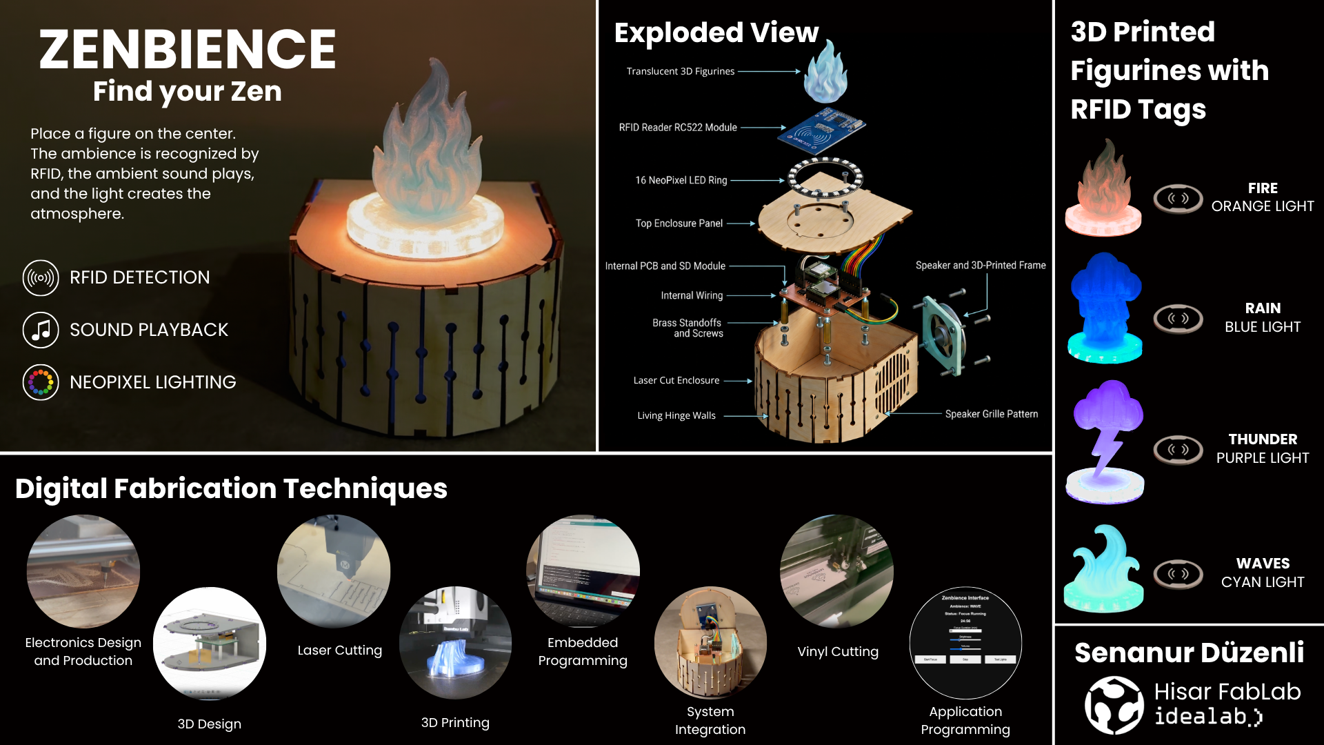
Final Project #
For my final project, I am aiming to create:
A tangible ambience device where physical interaction instantly transforms a space into a personalized immersive experience through synchronized light and sound.
Slide #
Video #
Hero Shots #
Ideation of Zenbience #
Coming up with a final project idea was a hard process. Knowing myself, I knew that I wanted to create some kind of a desk object. My first ideas included making a kinetic sculpture. However, that idea did not satisfy me enough to hold on to it.
I realized that I needed to personalize my idea in order to be satisfied with it.
For years, I have had struggles concentrating while studying or working on projects. If I am not in my hyperfocus mode, even the tiniest sounds will distract me from what I am doing (not even talking about the loud ones). What I discovered as a solution was having virtual ambiences or opening up ambience videos on Youtube to help me get in the zone.
Some examples that I have tried and found useful in the past:
- Hogwarts Library Ambience
- Cozy Scottish Castle Fireplace Ambience
- Thunderstorm in the Library Ambience
- A Soft Murmur ambient sound mixer
Inspired from these examples, I decided to make a desktop device that:
- keeps you focused and calm 🌿🧘🏻♀️
- keeps the ambience disconnected from the screen ✍🏼
- is pretty to look at 🥰
v1.0 #
Below, I present to you the first sketch of Zenbience. The device lets the user layer a number of ambient sounds on top of each other, creating the perfect ambience for their study or meditation (or whatever that demands focus).
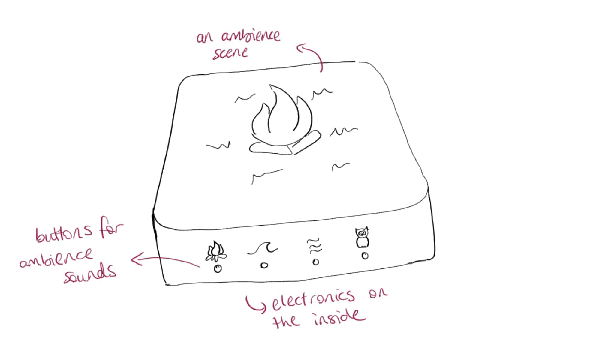
In short, Zenbience is a miniature ambience scene that lets users shape their environment through sound, supporting a focused state of mind.
Computer Aided Design #
For 3D design, I wanted to use the tool I am most familiar with.
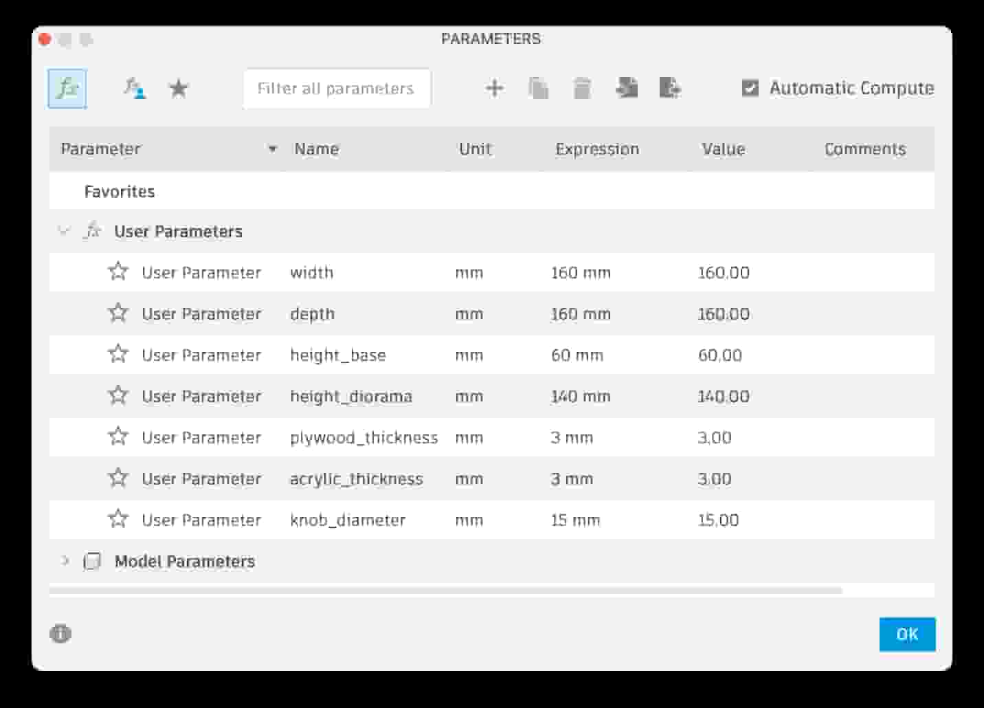
I used parametric modeling for to create the 3D design of my final project. However, for now, it is just a beginner level design to visualize my idea. I will have to make a plan on how to produce it and create the 3D design according to that plan.
Here is the video of how I designed the first sketch:
v2.0 #
Sketches #
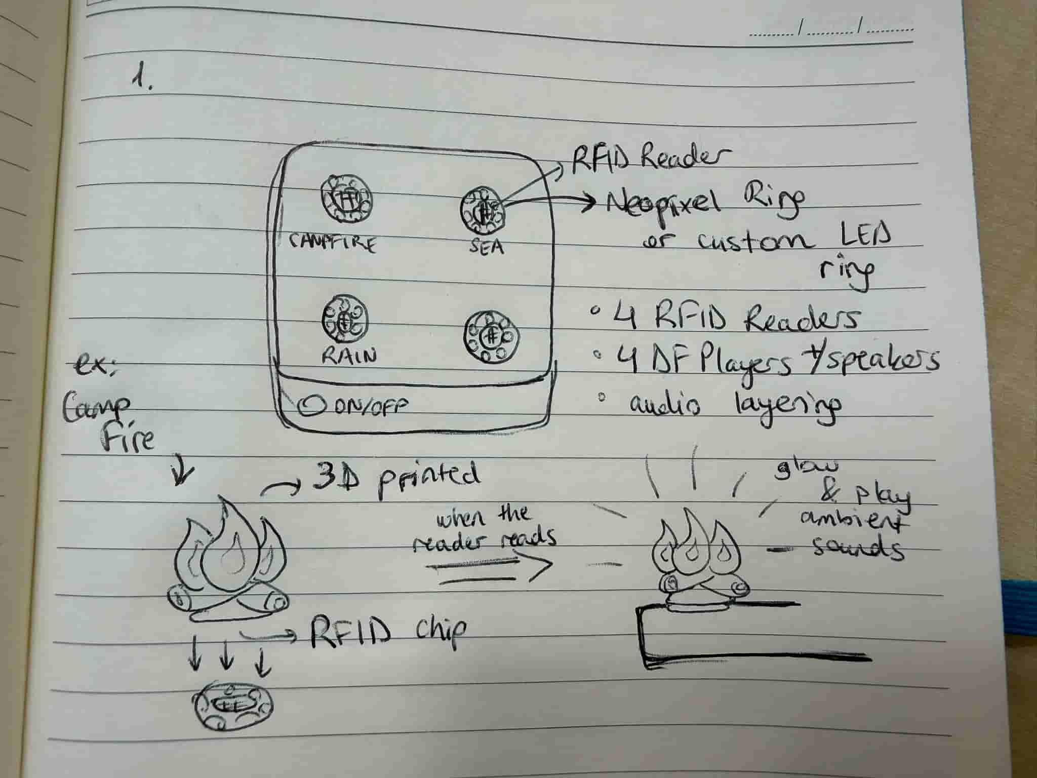
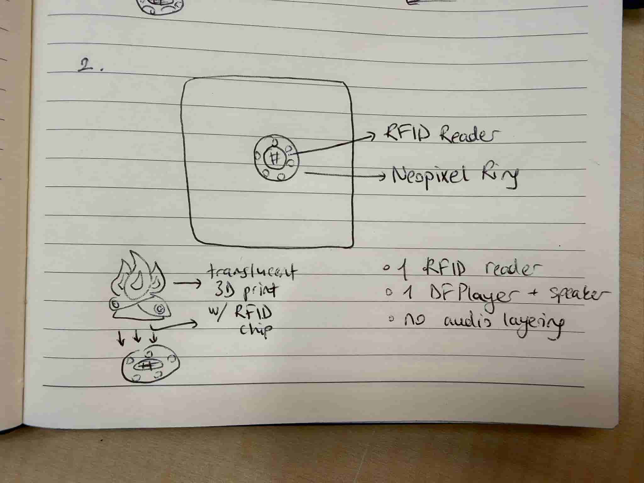
In v2.0 of the project, I decided to focus on creating an immersive ambience. Based on my research on the previous projects done by other people that I have discussed in Week 17, I decided to use an RFID reader and a Neopixel ring to enhance the immersive experience.
Below are the two options that I have thought about. However, using 4 RFID readers would be quite complex due to the limited pins that I have on the XIAO SEEED ESP32-C3. Therefore, I decided to continue with v2.2, and also get rid of the audio layering for simplicity.
v2.1: #
v2.2: #
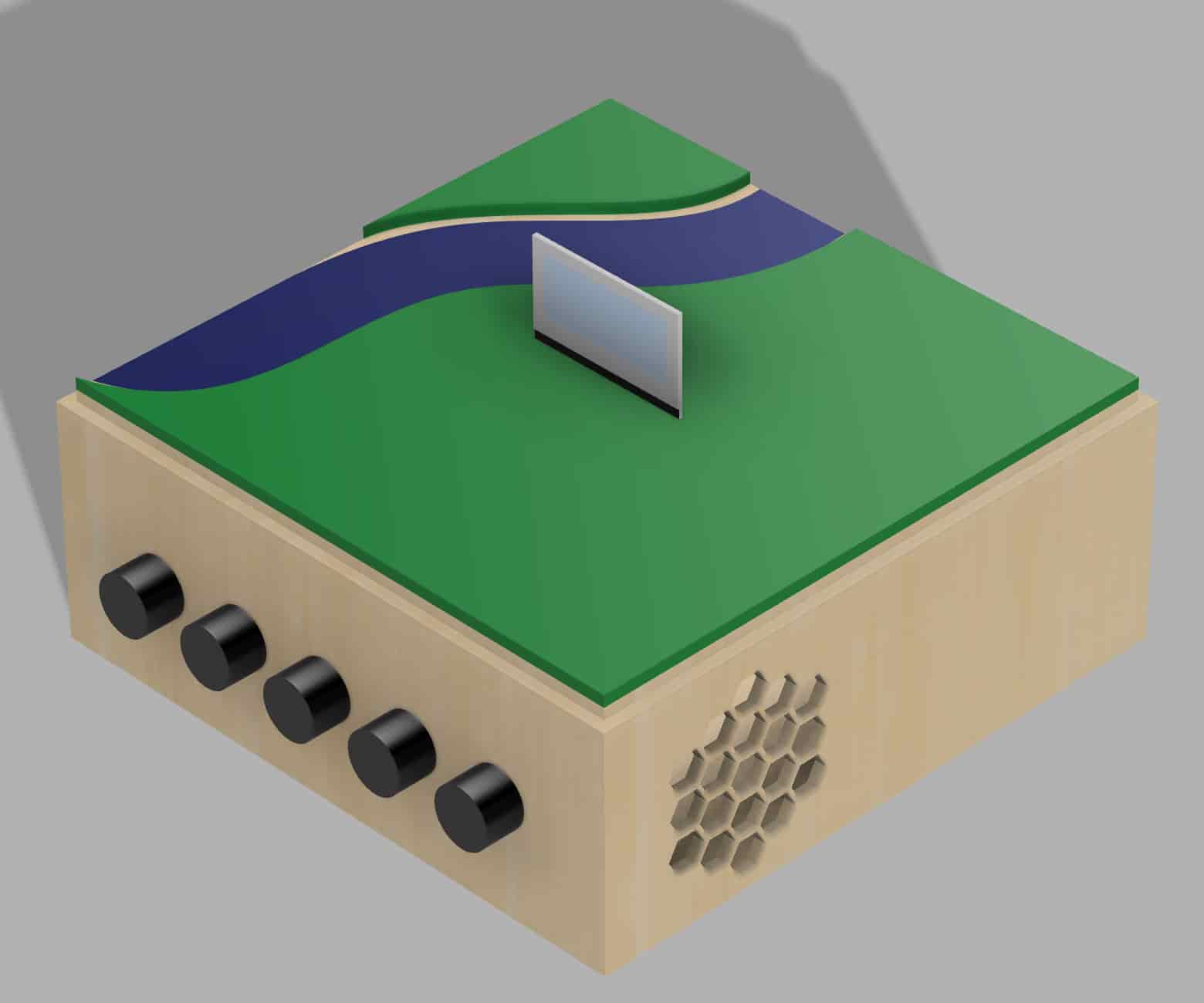
AI (ChatGPT) Generated Project Images:
I wanted to use plywood for the casing because wood gives the natural and grounded feeling of being present in the moment.
Embedded Design #
I gathered the electronic components for my idea. I used a breadboard to connect all of the components. I connected the speaker to the DFPlayer Mini.
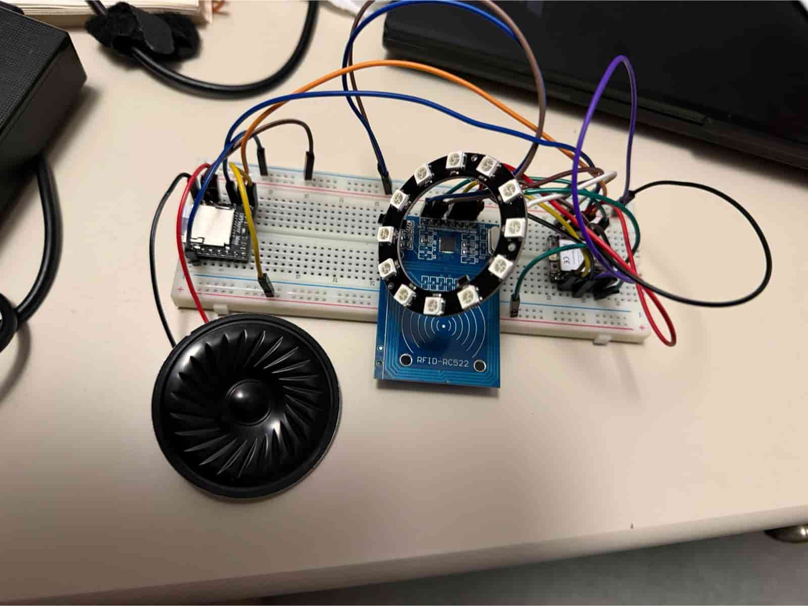
Then I asked ChatGPT to create a test code. The test code detects an RFID tag, lights the Neopixel ring, and plays the fire crackling sound. Below is a video of the test:
Electronics Design #
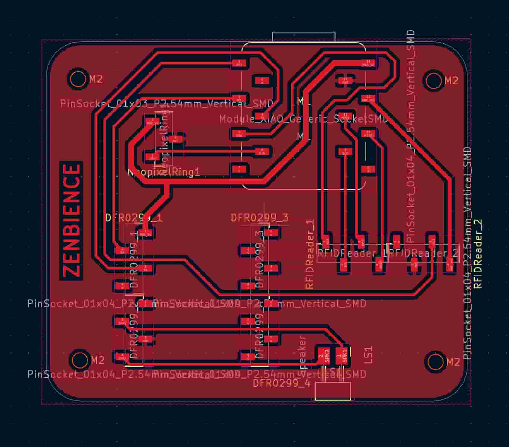
I did my Electronics Design on KiCAD. I downloaded the Fab KiCAD Library and used the symbols in that library. However, I couldn’t find any symbols for the RFID Reader and DFPlayer Mini. I used vertical pin sockets instead. I also added M2 mounting holes.
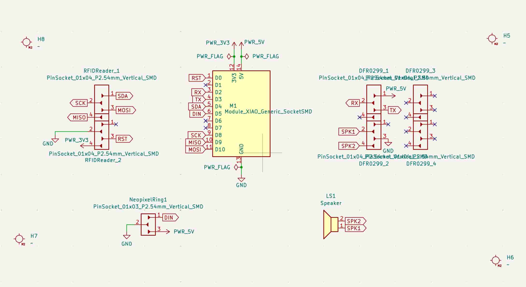
In the PCB Editor, I defined 2 track widths in addition to the 0.4mm netclass width: 0.6mm for 3v3 and 0.8mm for 5V power lines. It took a while to adjust the footprints optimally on the PCB. Also, I used the 0.0254mm grid to be able to place the vertical pin sockets accurately, since I did not have the footprints for the RFID Reader and DFPlayer Mini.
Electronics Production #
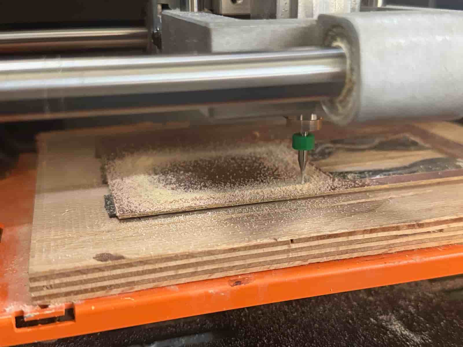
I download my PCB design files as .svg files and “resized the page to selection”. Then I saved the files. In the end I am left with an F.cu file and an Edge cuts file. Edge cuts defines the cutting lines (including the mounting holes) and F.cu defines all the tracks on the PCB.
After generating the g-codes on Mods Project, I did the production on Roland SRM-20.
For more details refer to my Week 8 documentation.
Midterm Review: #
So far, I have completed the ideation and the embedded system design. All of my components work. I have designed my PCB on KiCad and produced my microcontroller board. I also tested with the components soldered on my board.
What I have left are as follows:
- Finishing the Computer Aided Design
- Doing some tests with the laser cutter to figure out the best materials (wood vs. kraft paper), kerf, and joints
- Interface
- System integration
- Printing my 3D figures
Right now, as I am typing this, it is May28th. My presentation is on June 10th. My schedule will be as follows:
May 28th: Do laser cutting tests and finish up CAD
May 29th: Finish up CAD and interface
May 30th: Interface + CNC weekly assignment
June 1st: Manufacturing parts and system integration
June 2nd: Manufacturing parts and system integration
June 3rd: Finish up weekly documentation
June 4th-8th: System integration, tests, video and presentation
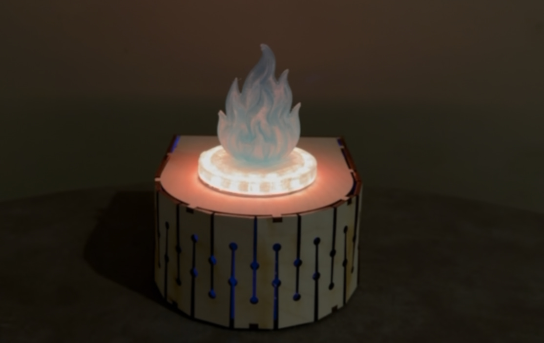
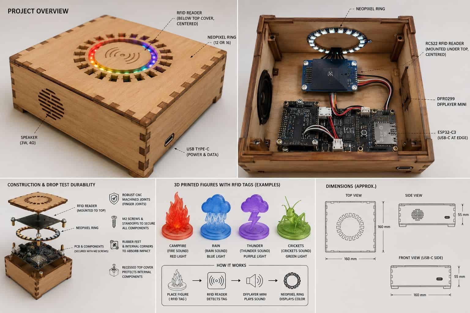
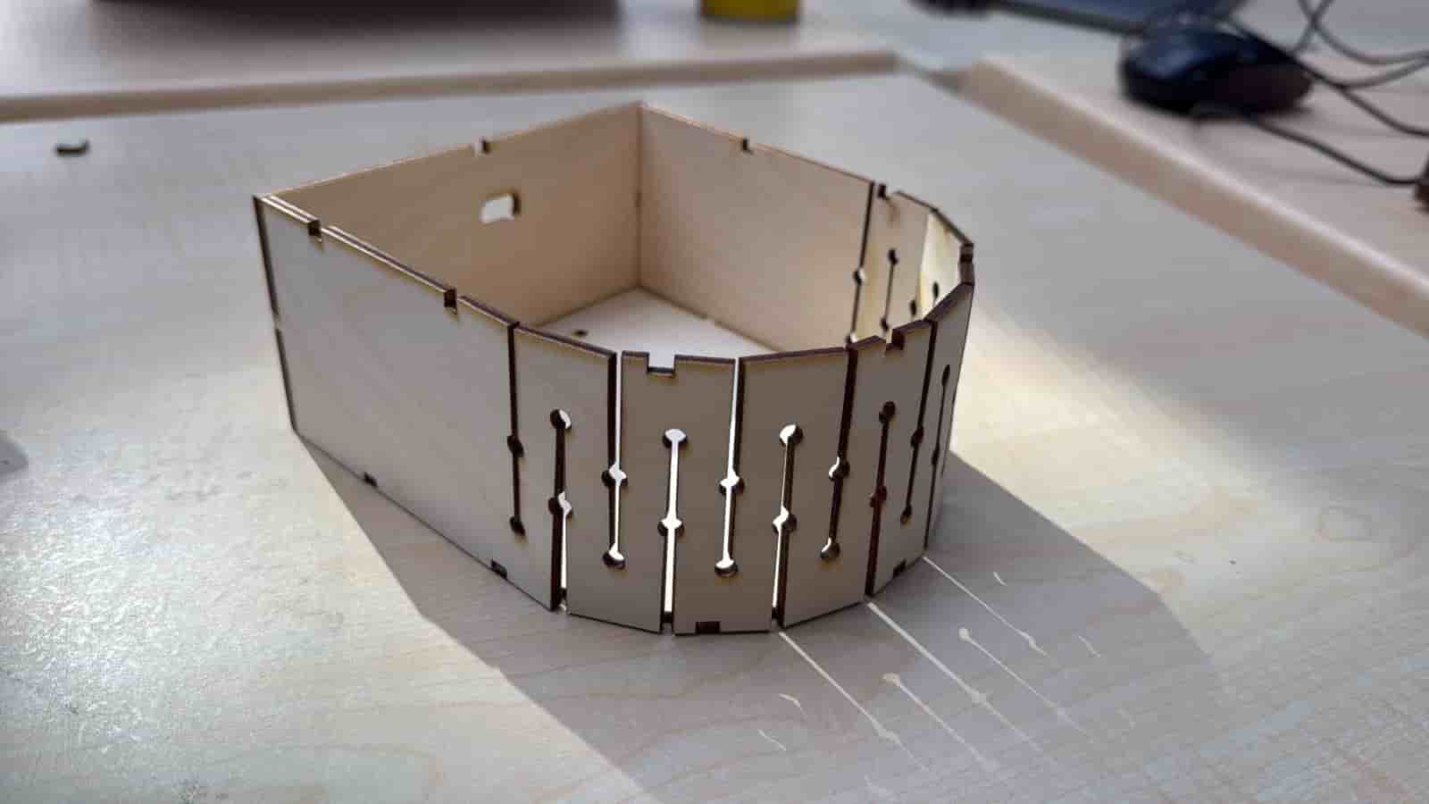
Laser Cut Enclosure with 3D Design #
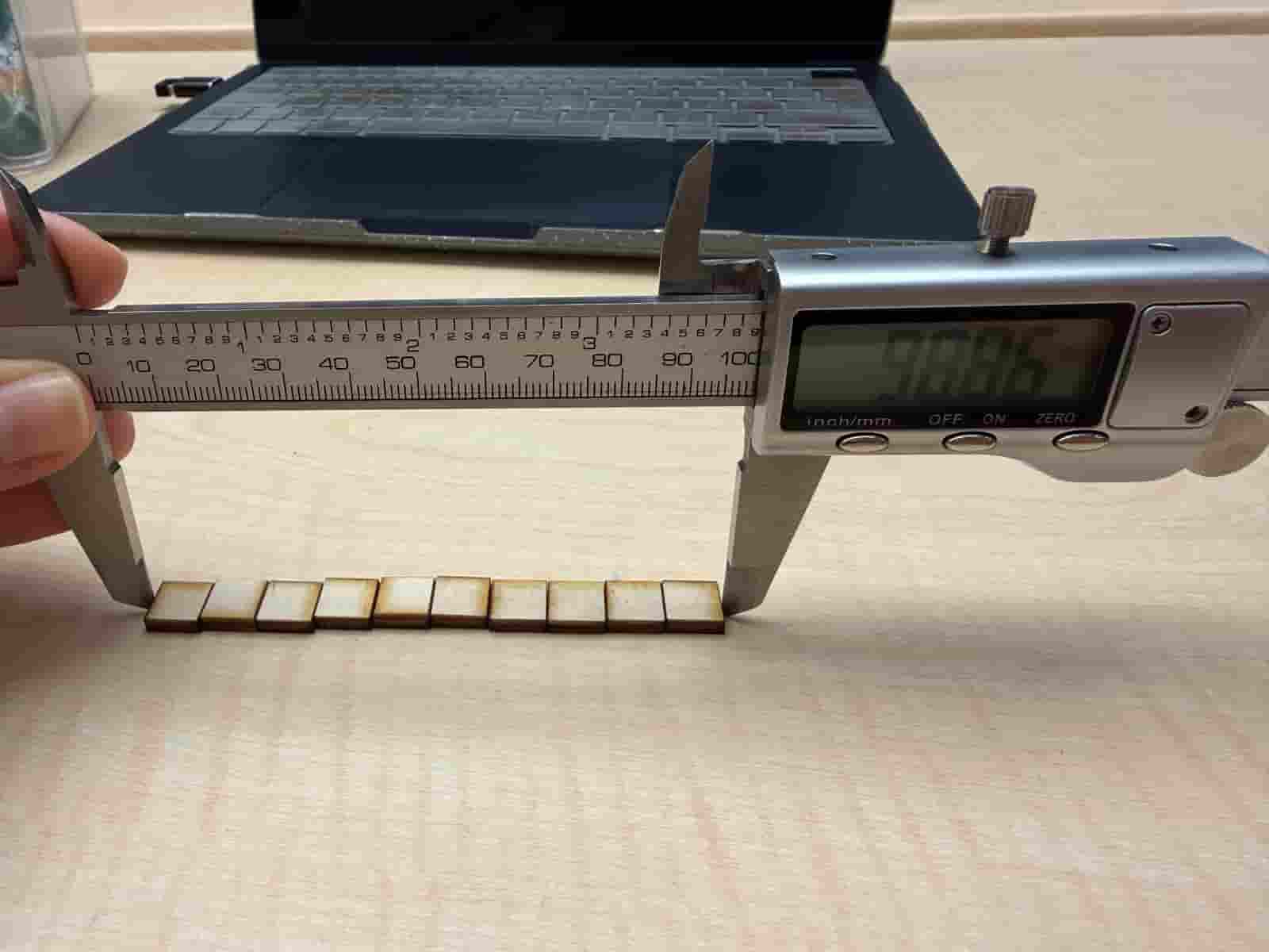
I created a Kerf Test file that cuts 10 10mmX10mm squares. When measured with a digital caliper, it should ideally give me 100mm, but instead it read 98,86. This means that there is a loss of 1,14mm in the material. I divide it by 10 (since 10 squares) and I get 0,114mm. This is the kerf. I will divide this by 2 to use in my designs, which give me a value of 0,057.
3D Design #
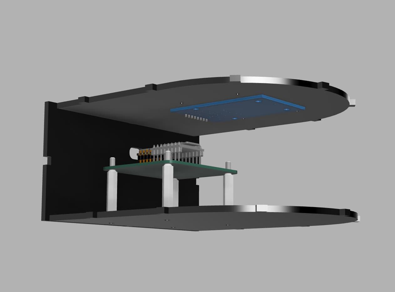
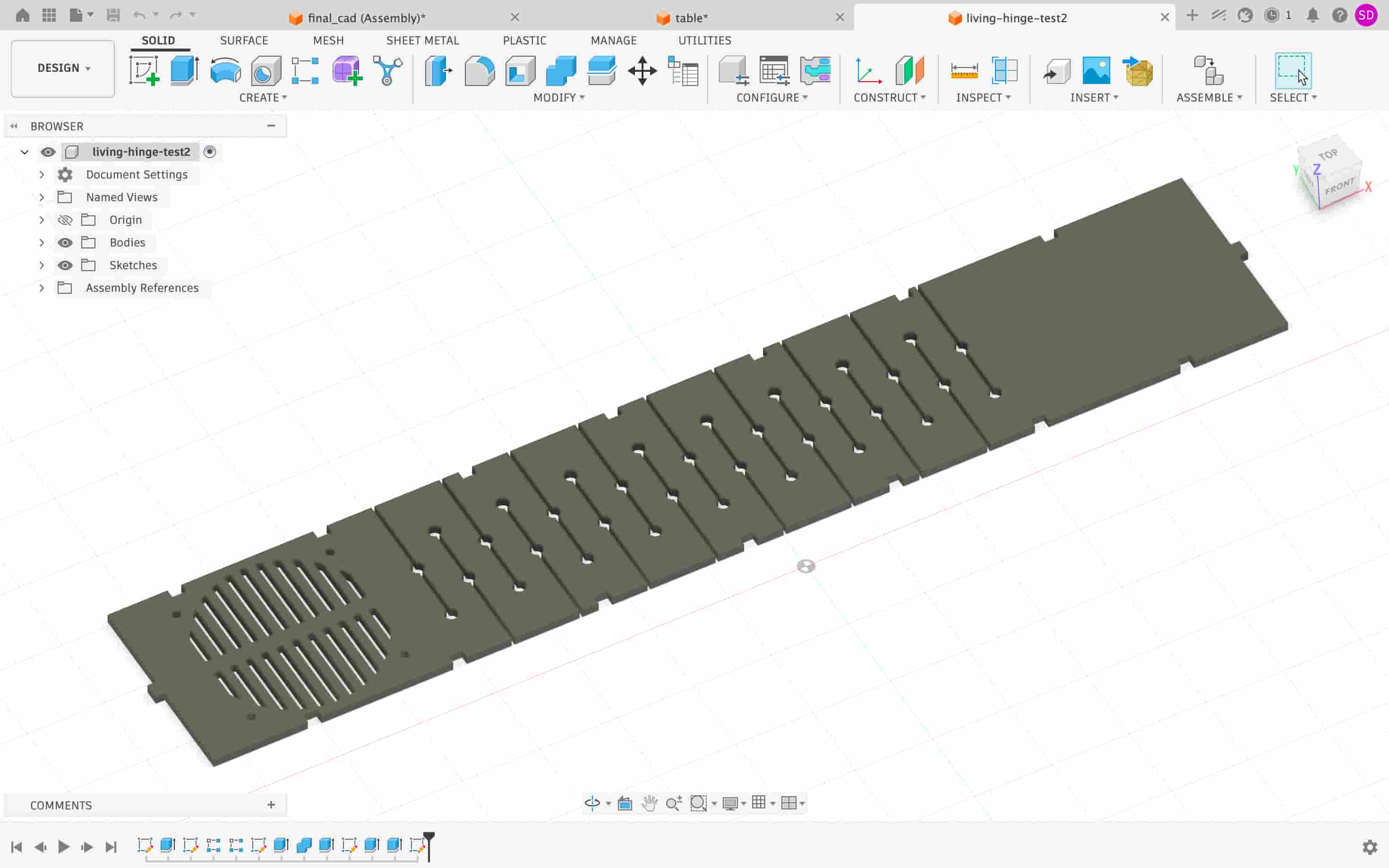
I designed the 3D CAD in Fusion 360. The rounded side on the enclosure will be a living hinge. The joints are mathematically calculated to connect seamlessly to the living hinge side. One trick here is to use components designed by other people online. I used GrabCAD to find 3D models of standoff spacer, neopixel, rfid reader, esp32-c3, and dfplayer mini. I designed the enclosure around this setup. It was easier than to CAD from 0!
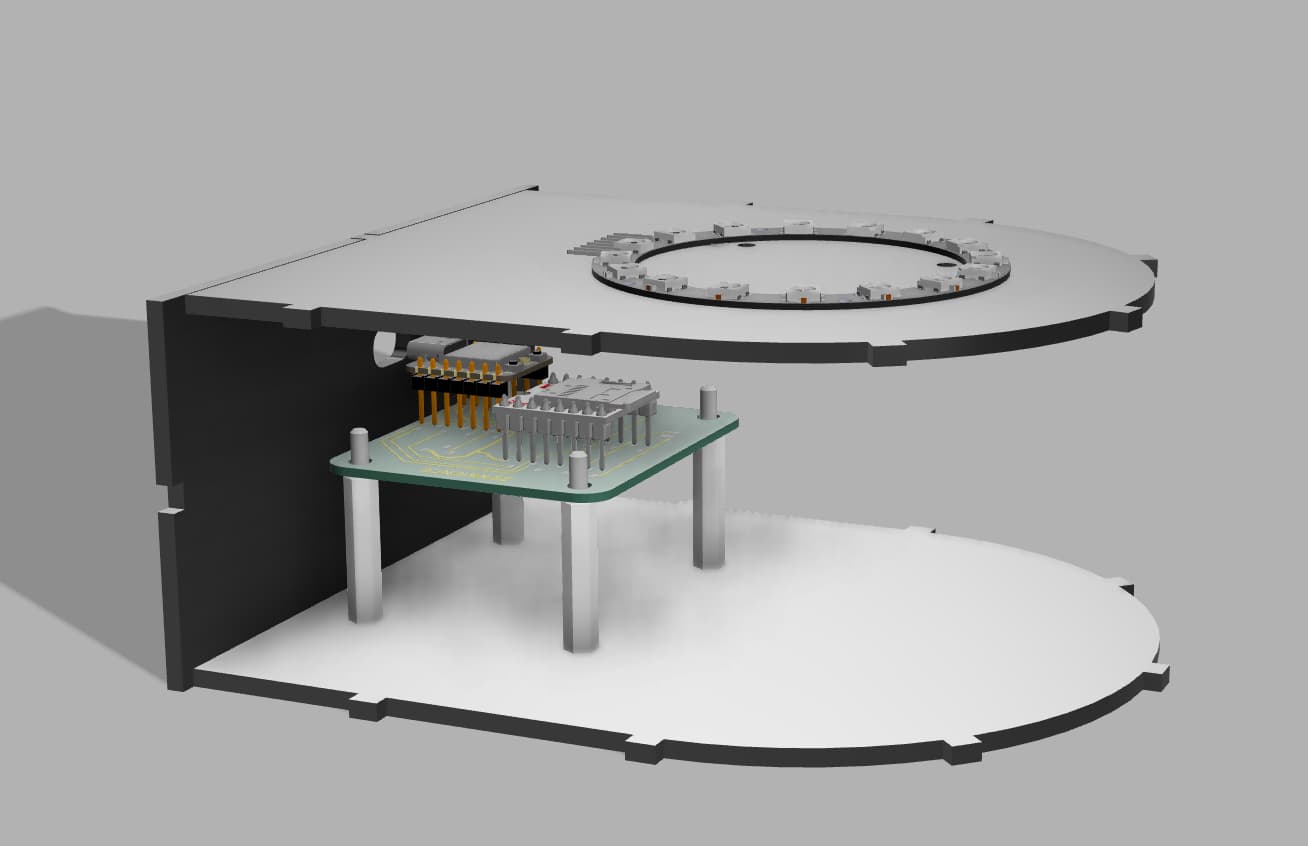
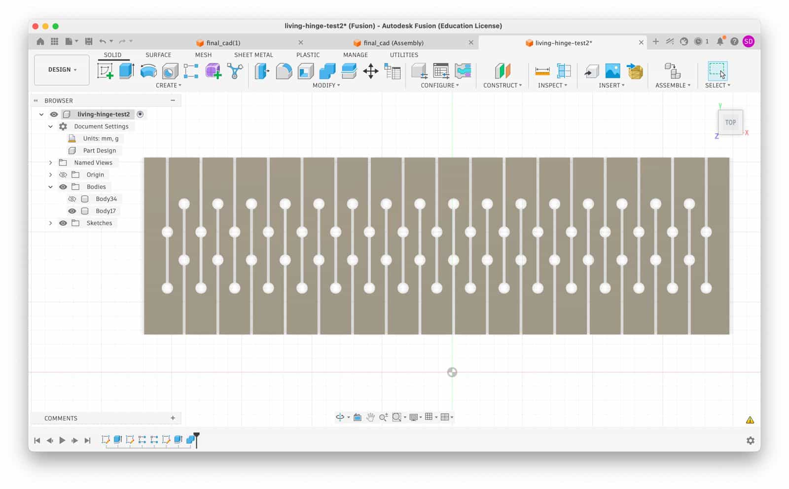
For the living hinge part of the enclosure, I calculated the half of the circumference of the 60mm diameter circle by calculating (pi * r), where pi is 3,14 and r is 60mm. The result gives me 188,5mm. I add 10mm on each side to make sure the joints on the base are covered. The overall length for the living hinge becomes 208,5mm. The design becomes like this:
Laser Cutting #
I then use the laser cutter to manufacture my enclosure. After a few iterations, I successfully manage to set all the parameters right.
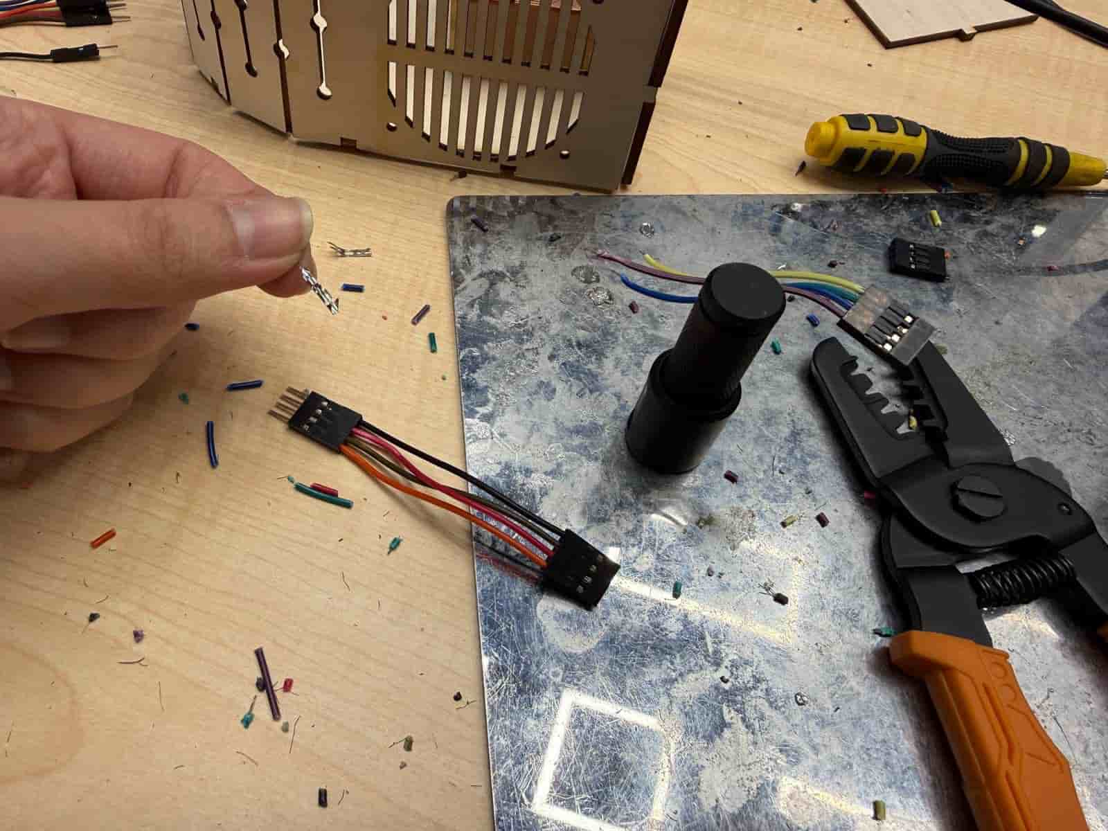
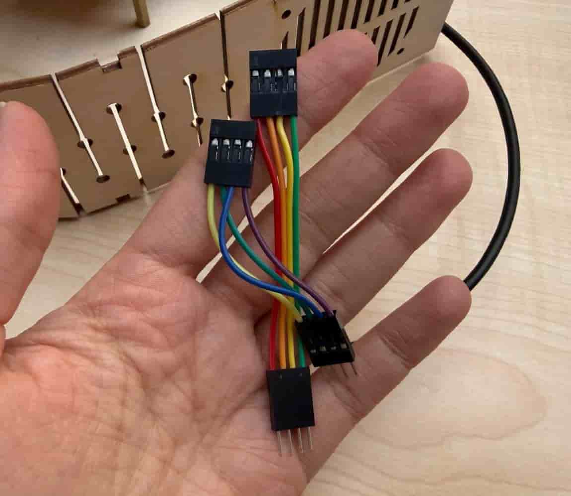
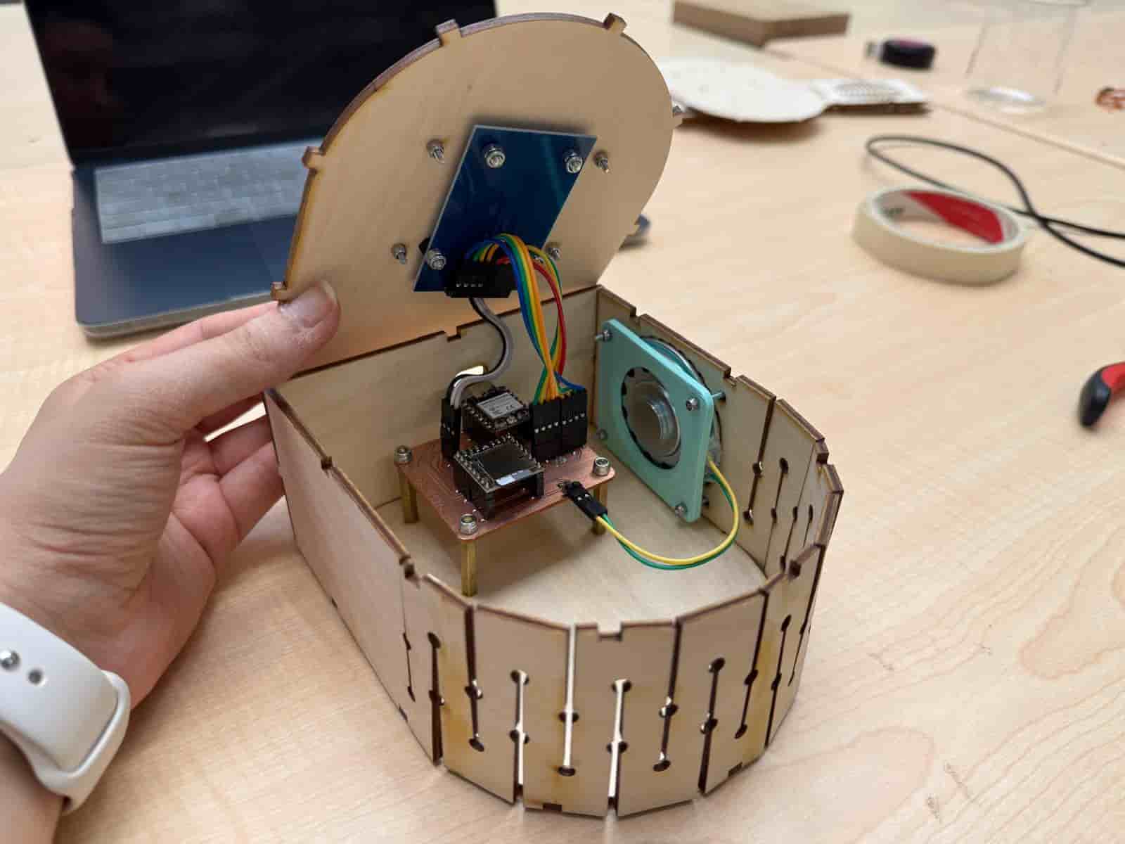
System Integration #
I wanted a clean system integration. That is why, after securing my electronic parts, I shortened some jumper wires and did iterations and iterations of crimping.) Crimping is sometimes hard and frustrating. However, Kris’s tutorials were very helpful.)
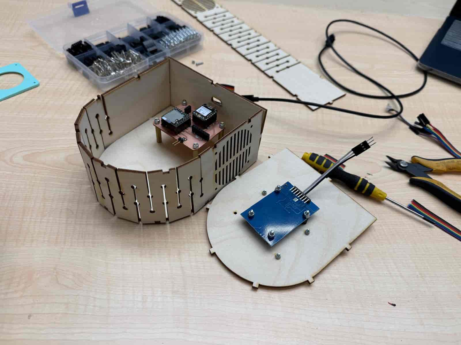
I also 3D designed and printed a holder for the speaker. Then, I assembled the system using standoff spacers, screws, and fiber nuts, ensuring that my electronic parts were in tact inside the enclosure. My main goal was to have no sounds when I shook the package. And I achieved it.
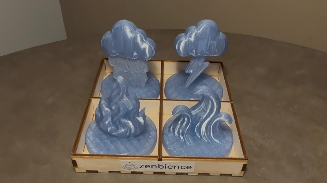
3D Figurines #
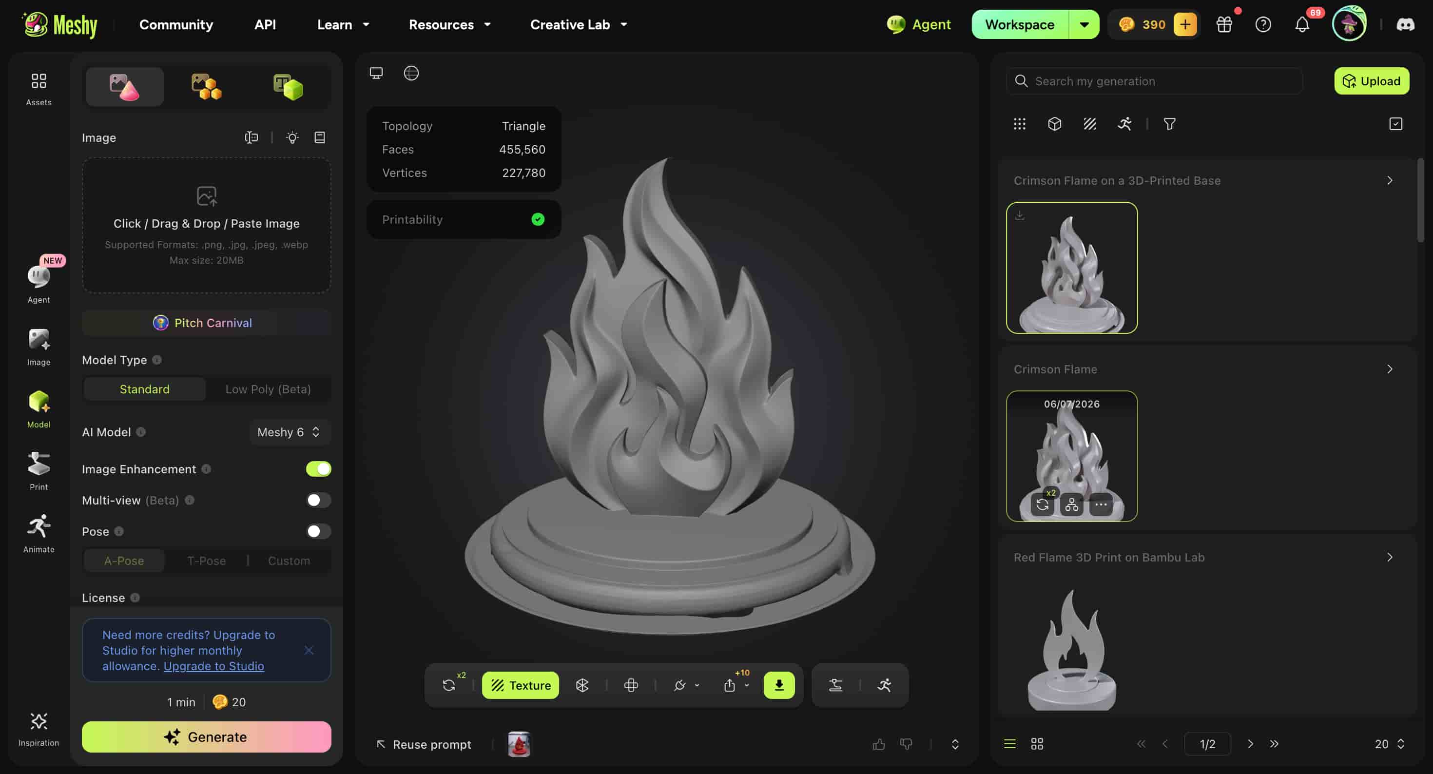
My project needed some 3D figurines with RFID tags. I decided to use Meshy.ai for this purpose. I gave an image and it created the figurines for me. I also had to do some post-processing in Fusion360.
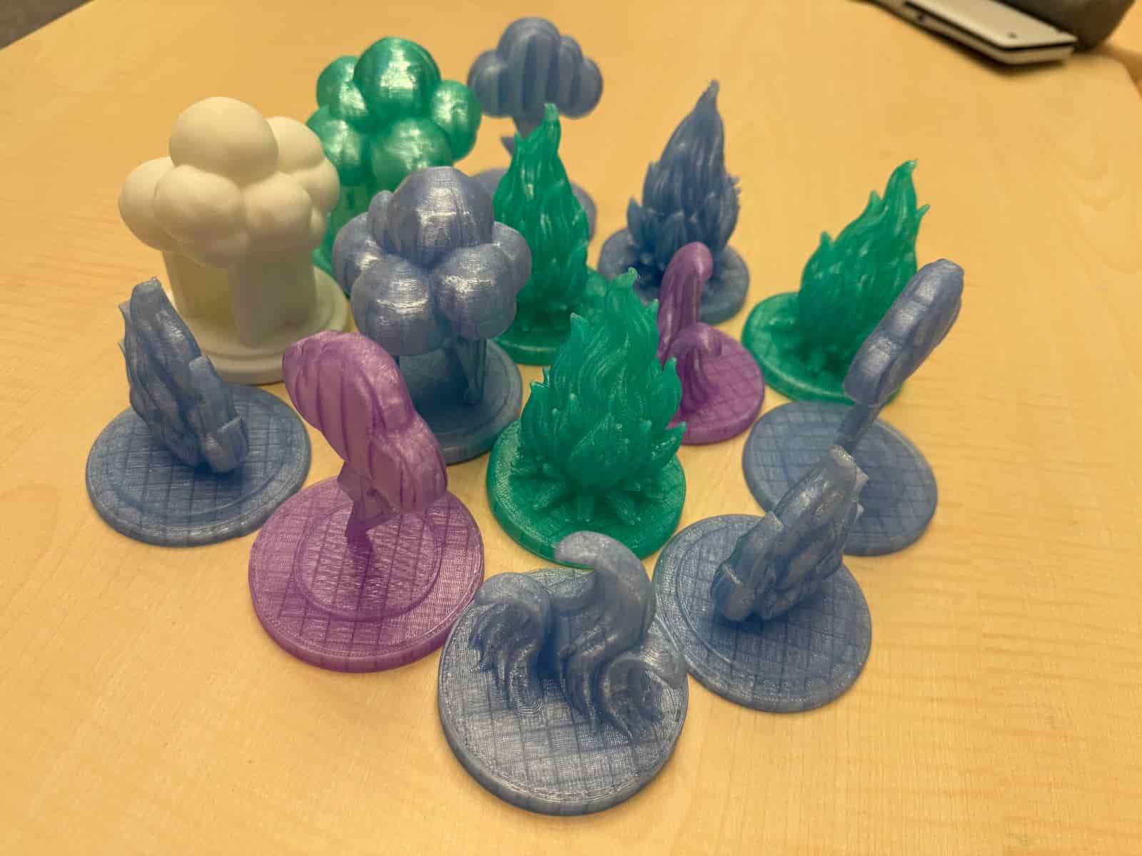
I printed the 4 figurines (Fire, Rain, Thunder, Waves) using transparent PETG filament. We had a few at the lab, so it is safe to say that I had a few printed figurines.) I also had a chance to experiment a little with changing nozzle temperatures and and speeds and other settings. Because PETG requires different settings than PLA, like higher temperatures.
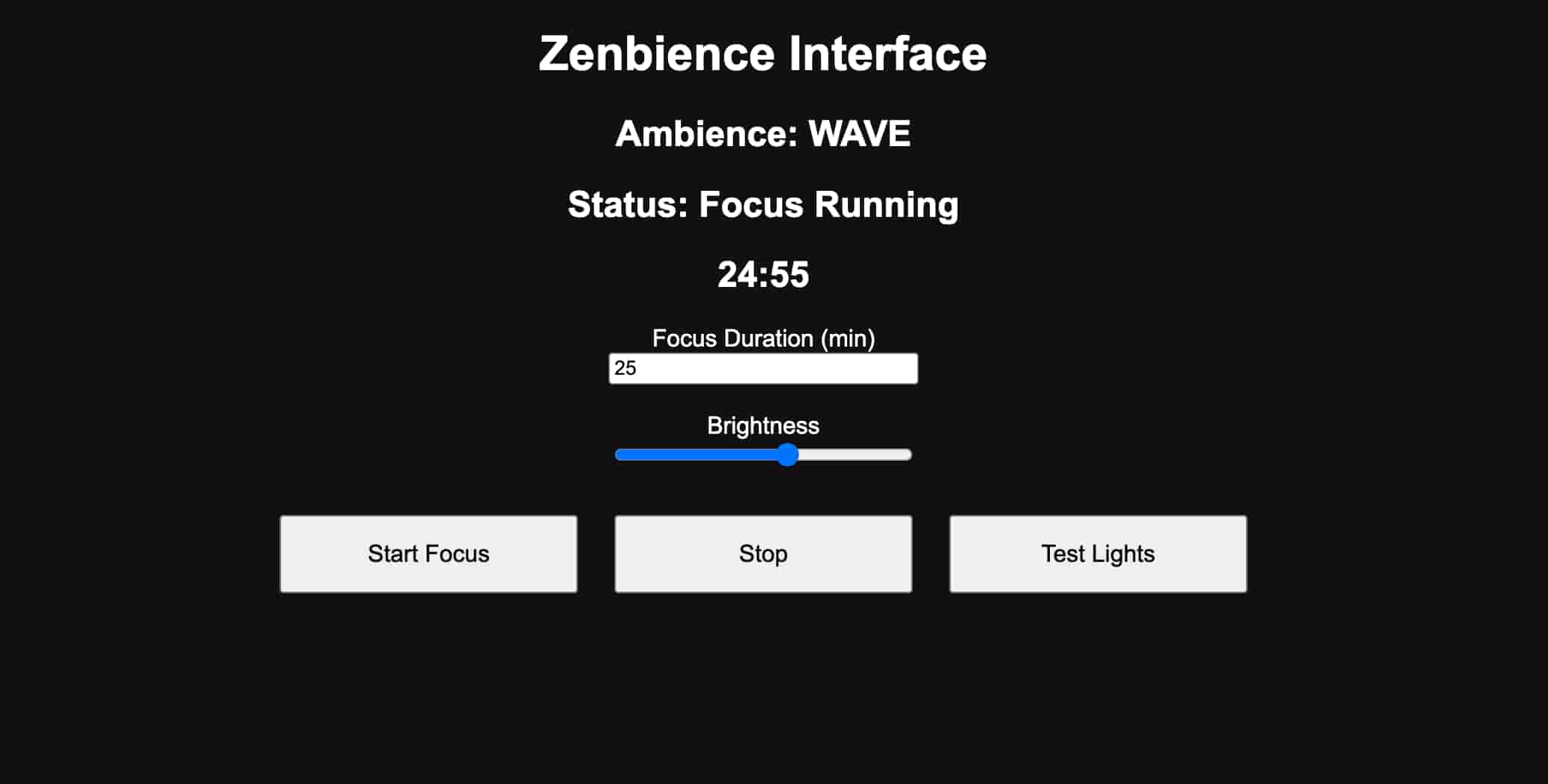
Interface and Application Programming #
I designed a web-based user interface for Zenbience using the XIAO ESP32-C3. The ESP32 hosts an HTML/CSS/JavaScript webpage that allows users to start focus sessions, adjust brightness and volume, monitor the current ambience mode, and view the countdown timer over Wi-Fi. The interface communicates with the embedded firmware through HTTP requests and integrates with the RFID reader, NeoPixel LEDs, and DFPlayer Mini.
The development process, implementation details, and source code are documented in Week 14 page.
Final Product #
The final product successfully creates tangible ambience, transforming sound, light, and atmosphere into a personalized experience.
BOM List: #
| Component | Estimated Cost (TRY) | Estimated Cost (USD) |
|---|---|---|
| SEEED XIAO ESP32-C3 | 350 | 7.61 |
| DFR0299 DFPlayer Mini | 120 | 2.61 |
| WS2812 NeoPixel Ring 16 | 250 | 5.44 |
| 8Ω 0.5W Speaker | 50 | 1.09 |
| RC522 RFID Module | 100 | 2.18 |
| 64GB SD Card | 700 | 15.23 |
| Fasteners and Wiring | 100 | 2.18 |
| Copper Clad Board | 100 | 2.18 |
| 3mm plywood | 150 | 3.26 |
| Transparent PETG Filament | 500 | 10.9 |
| PLA Filament | 100 | 2.18 |
| Estimated Total | 2520 | 54.86 |
Related Weekly Work: #
- Computer Aided Design
- Embedded Programming
- Electronics Design
- Electronics Production
- Input Devices
- Output Devices
- Networking and Communications
- Interface and Application Programming
- System Integration
- Applications and Implications
- Invention, Intellectual Property, and Income
Files:
- Interface (.ino) (replace WiFi information)
- CAD Files
- 3D Figurines (.3mf)