Week 8 - Electronics Production #
Hero Shot: #
TL;DR #
I redesigned my microcontroller development board in KiCad to make it smaller, then exported the PCB layers as SVG files. Using Inkscape and Mods Project, I generated toolpaths for the Roland SRM-20 and milled the PCB traces and outline. After cleaning the board, I soldered the headers and sockets, checked connections with a multimeter to prevent short circuits, connected the components, and successfully tested the PCB.
Group Assignment #
Link to this week’s group assignment
PCB Production with Roland SRM-20 #
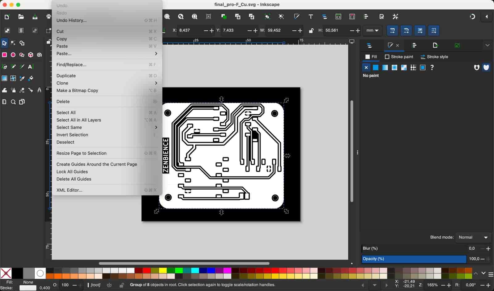
For my Electronics Production week individual assignment, I fabricated and tested a custom microcontroller development board based on the PCB I designed during Electronics Design week. I first optimized the original design in KiCad by making the PCB layout more compact. After finalizing the board, I exported the F.Cu and Edge Cuts layers as SVG files. In Inkscape, I used the “Resize Document to Selection” option to ensure the document dimensions matched the PCB size exactly, which is important for accurate toolpath generation.
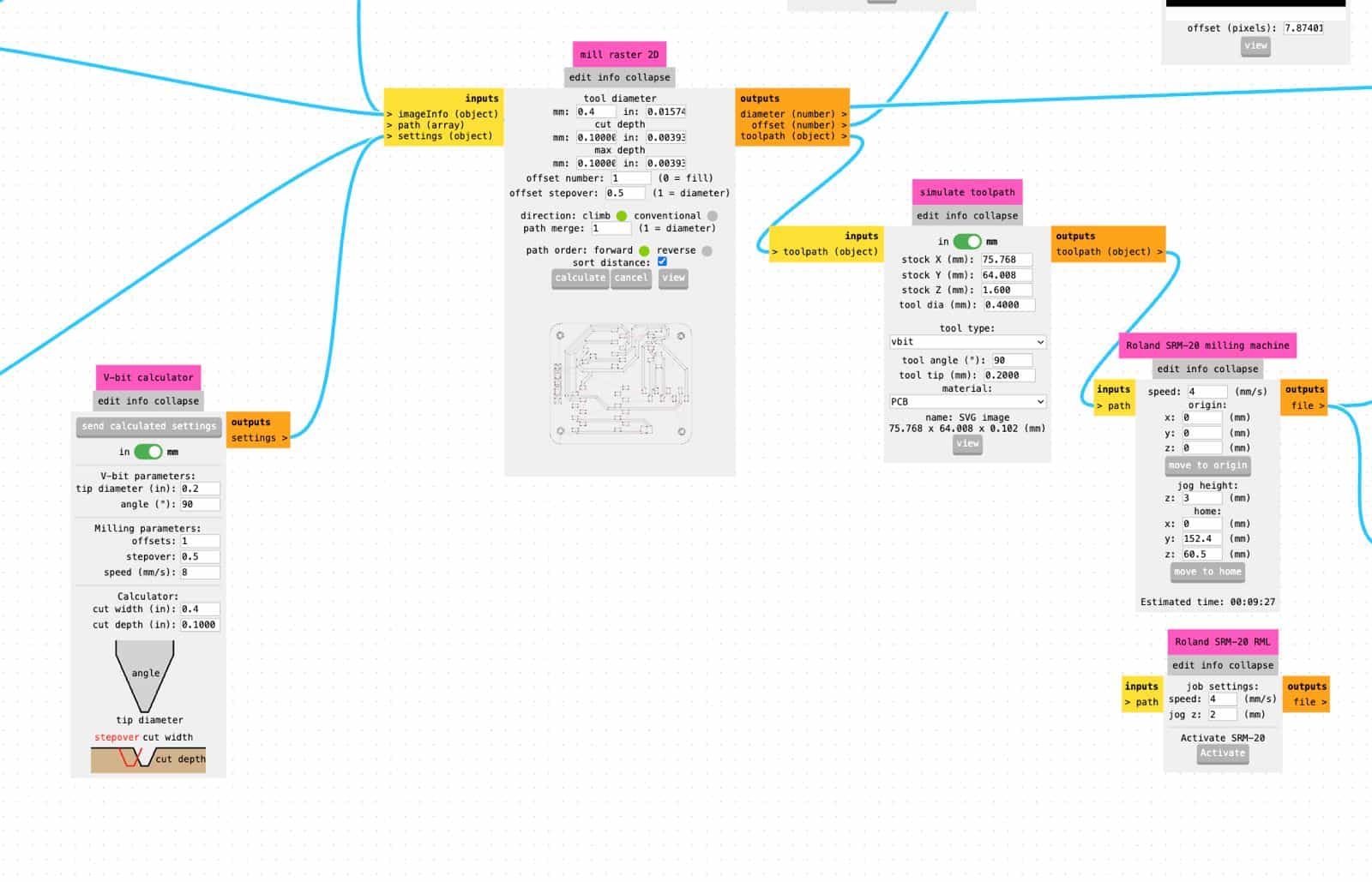
To prepare the milling files, I used Mods Project, the browser-based CAM workflow developed by the Center for Bits and Atoms. Inside Mods, I selected the Roland SRM-20 mill 2D PCB workflow to generate the G-code/toolpaths for both the copper traces (F.Cu) and the board outline (Edge Cuts).
These are the settings I used for F.Cu:
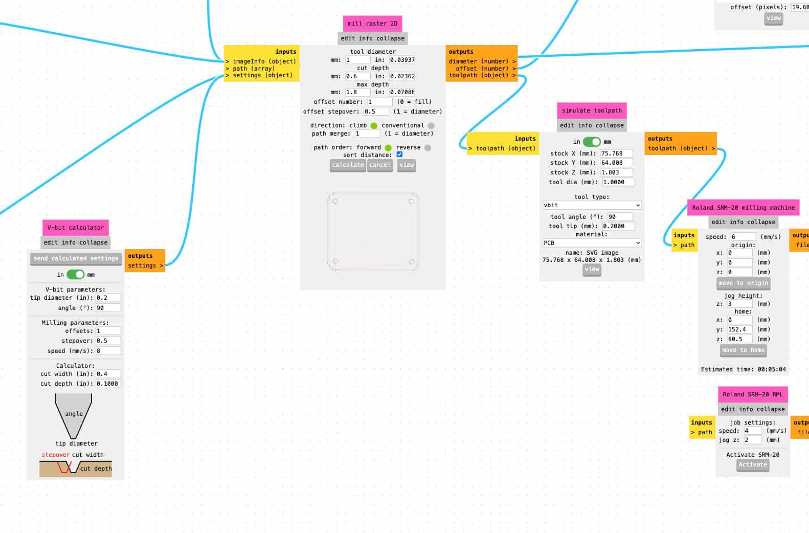
These are the settings I used for Edge Cuts:
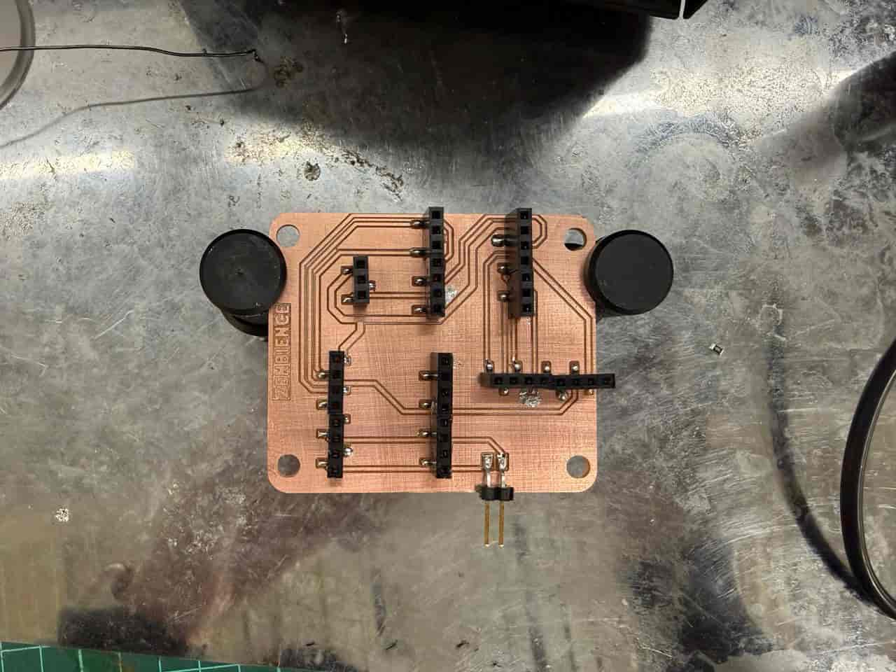
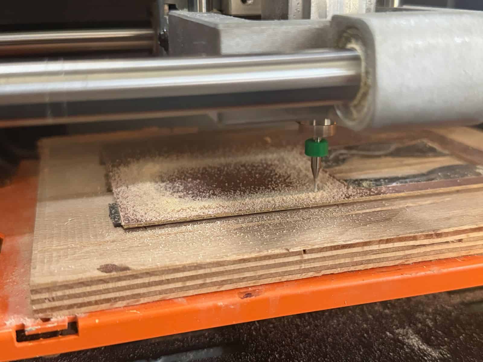
I used a piece of double-sided tape to securely fix the copper-clad board onto the bed of the Roland SRM-20 before starting the milling process. After generating the files, I milled the PCB in two stages: first the F.Cu traces, then the Edge Cuts outline.
Once milling was complete, I cleaned the PCB surface using isopropyl alcohol (aka IPA) to remove dust and residue. I then soldered the pin headers and sockets onto the board. During soldering, I continuously checked the electrical connections with a multimeter to verify continuity and prevent short circuits.
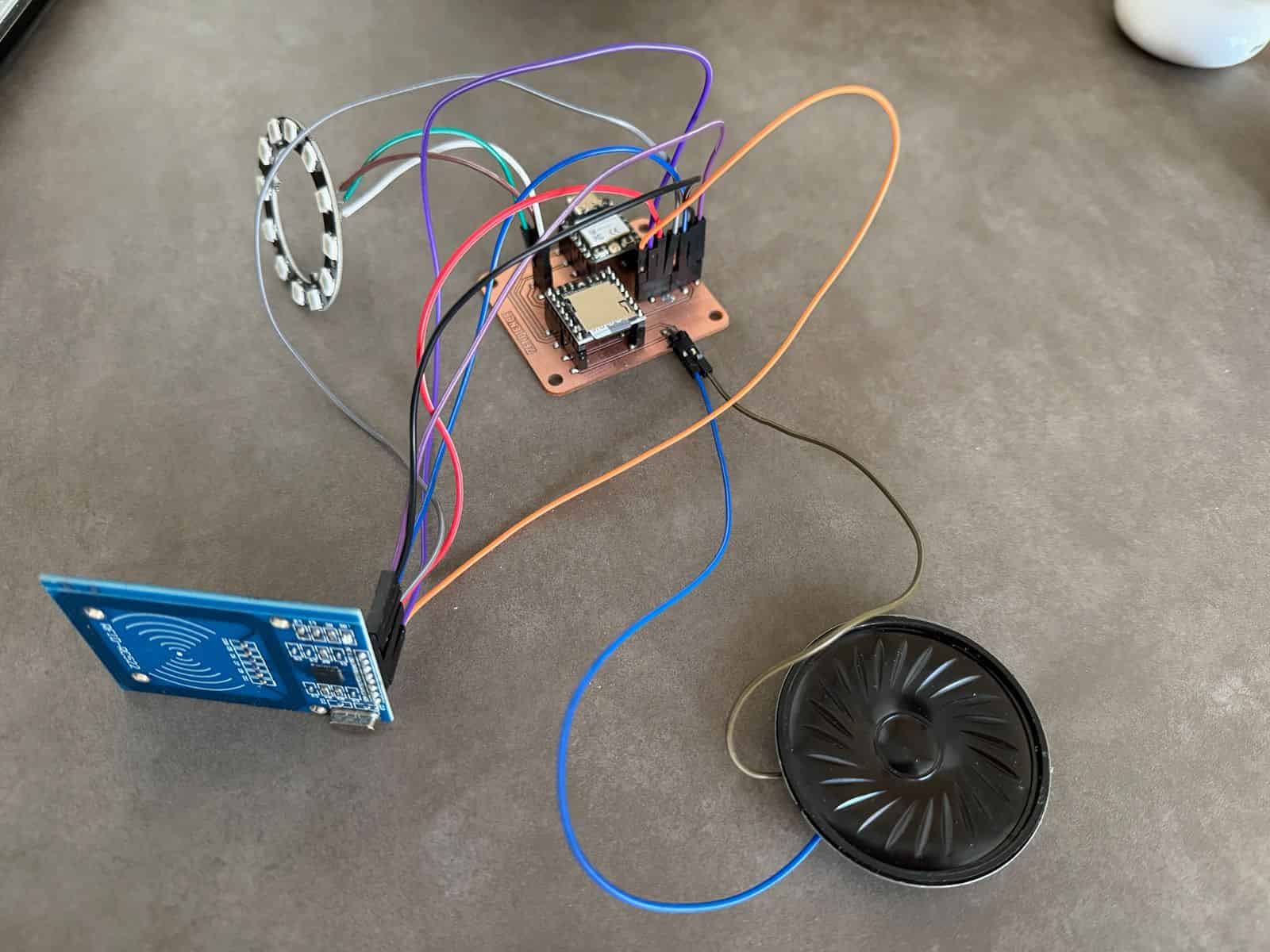
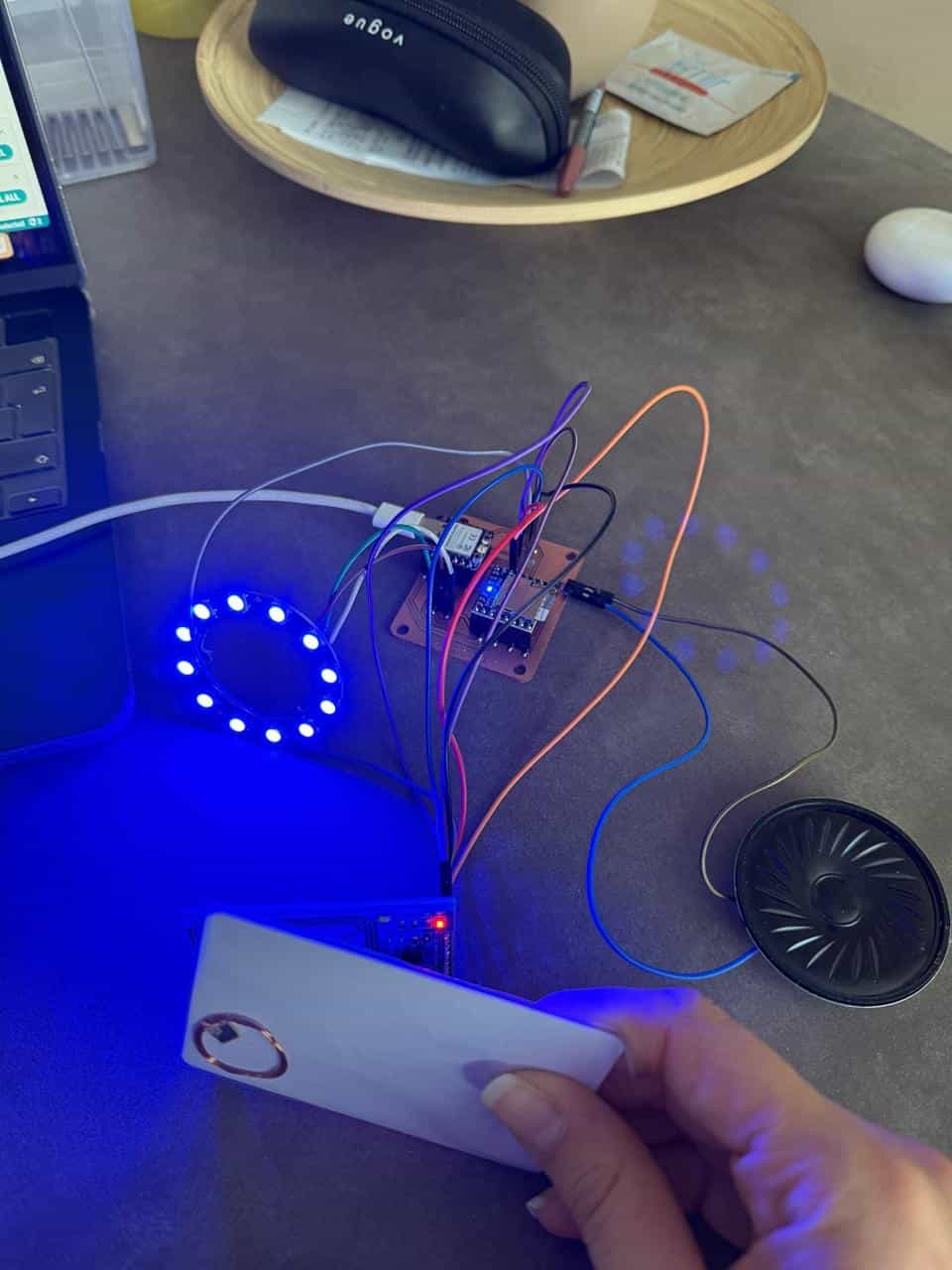
Finally, I connected the external components and successfully tested the PCB to confirm that the board functioned correctly.
Files: