Week 7 - Computer-Controlled Machining #
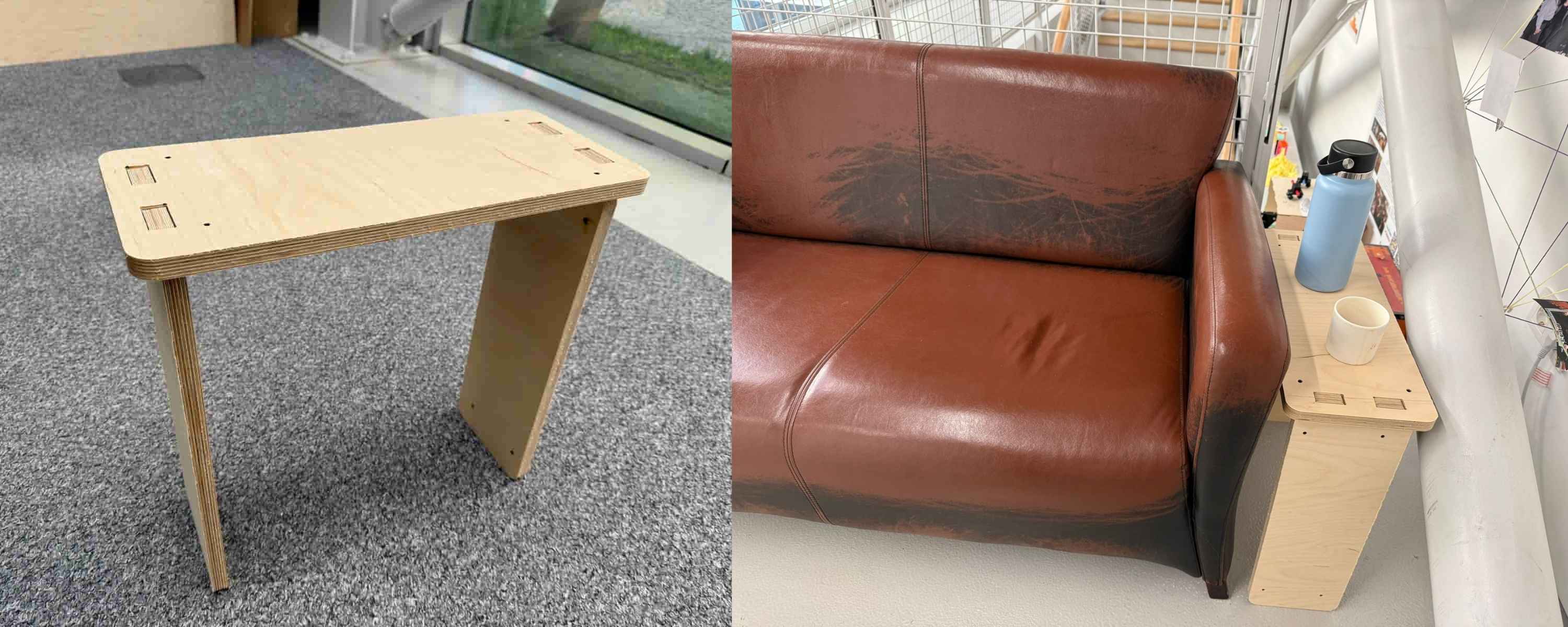
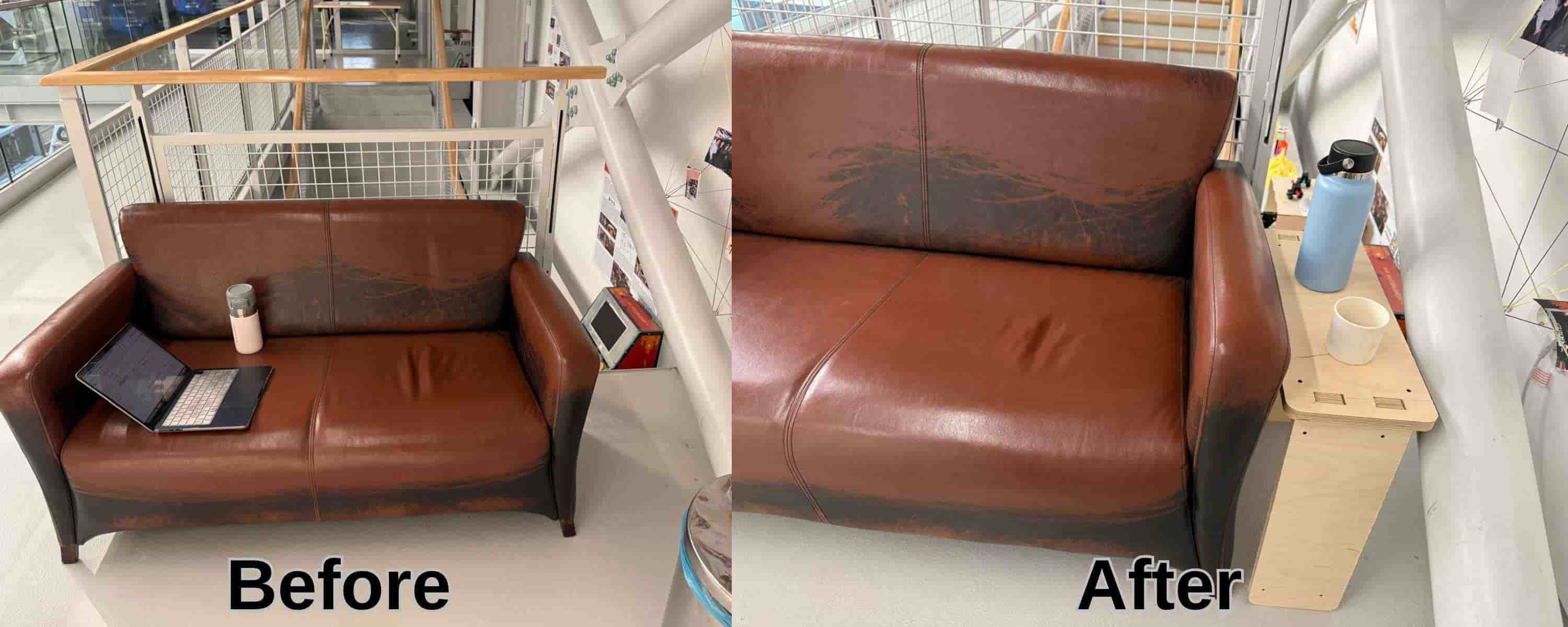
Hero Shot: #
TL;DR #
This week, I designed and fabricated a full-size coffee table for our lab’s break area using parametric design and CNC machining. After creating the model with press-fit joints and dogbone fillets, I exported the design as a DXF file and generated pocket and profile toolpaths in VCarve. The parts were machined from 20 mm plywood using a CNC router, then assembled into a functional coffee table without the need for additional fasteners.
Group Assignment #
Link to this week’s group assignment
Manufacturing a Coffee Table #
For the Computer-Controlled Machining week, I designed, milled, and assembled a full-size coffee table for the break area in our lab. The table was intended to fit in the empty space next to the couch and provide a practical surface for coffee and other items.
Parametric Design #
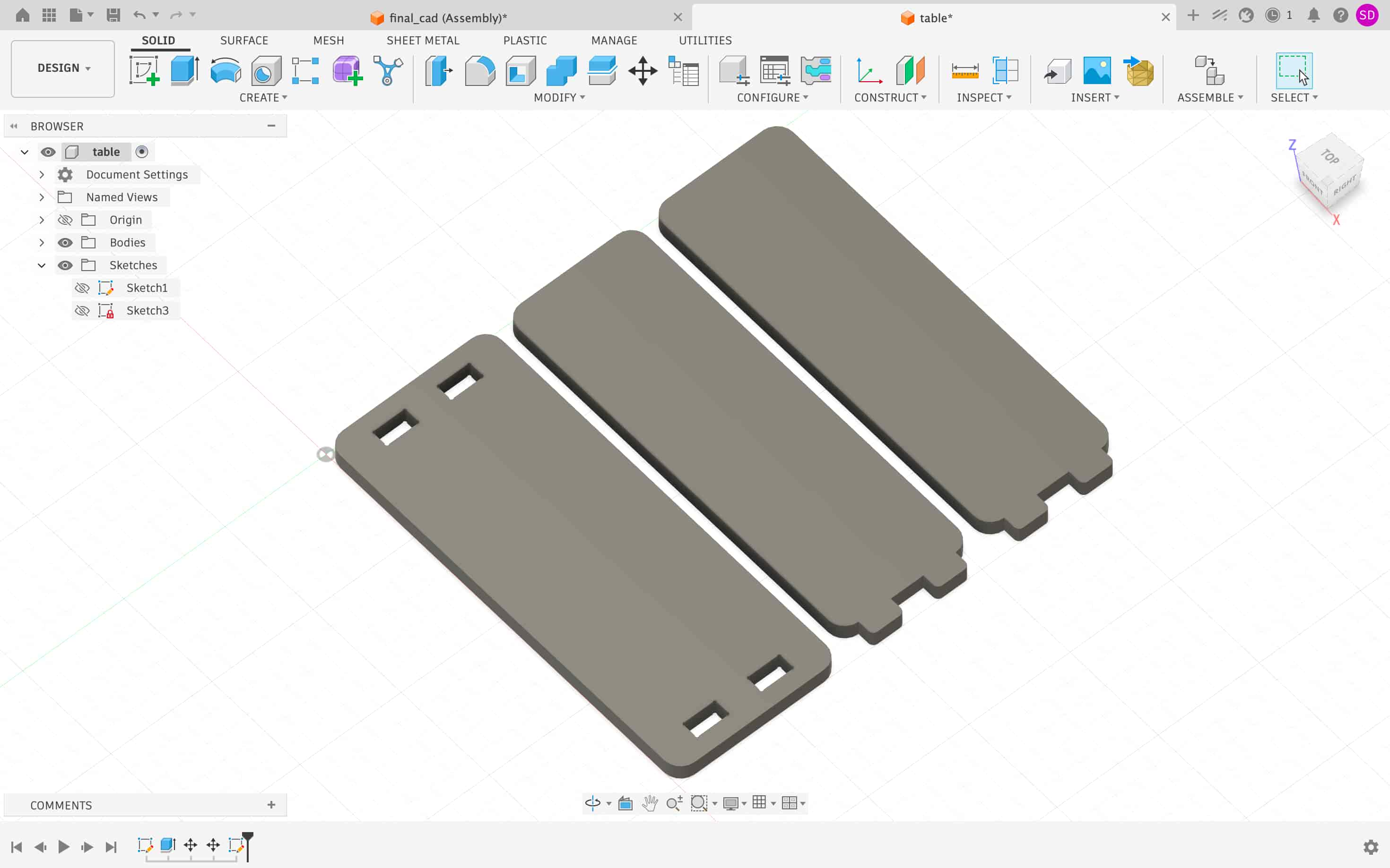
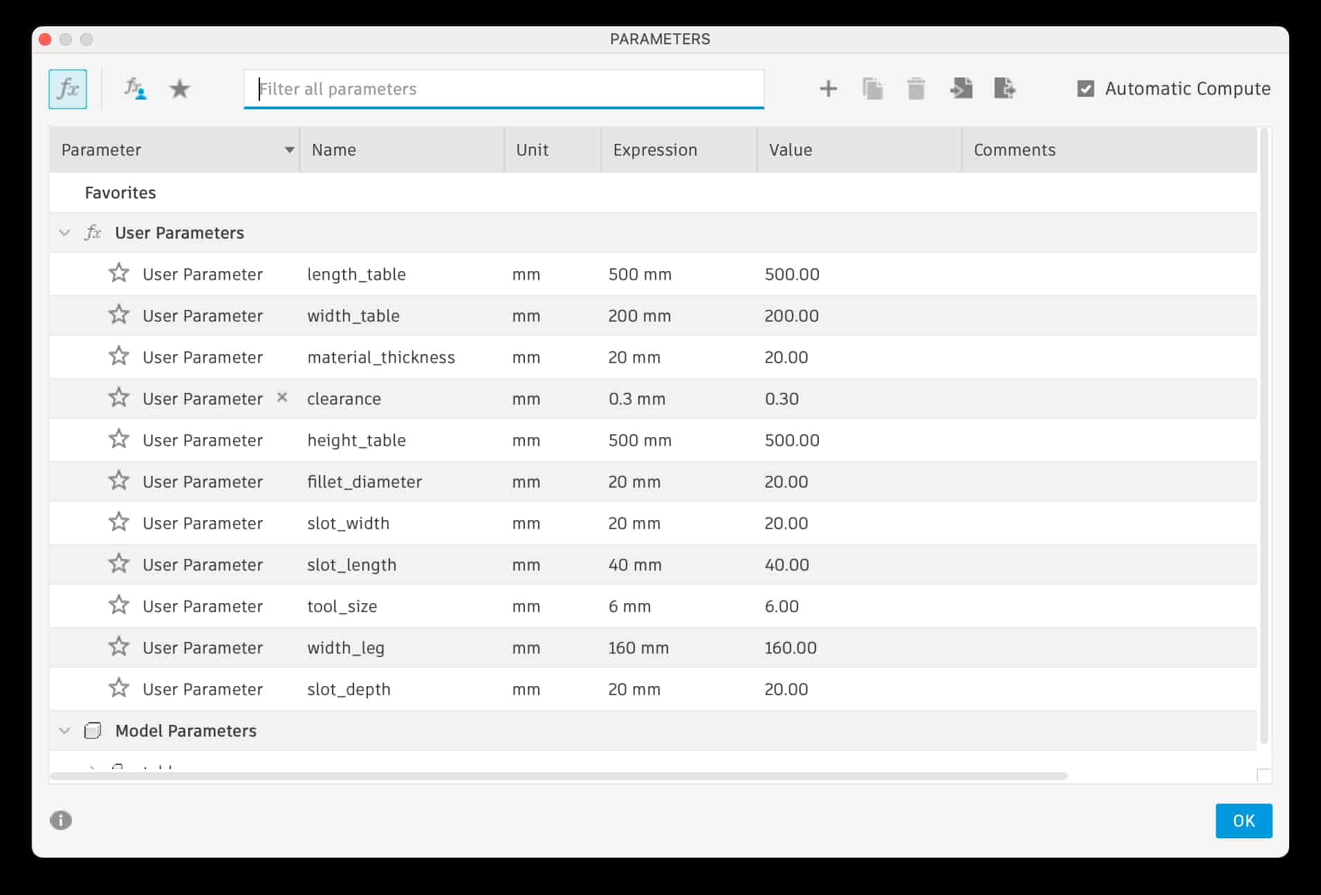
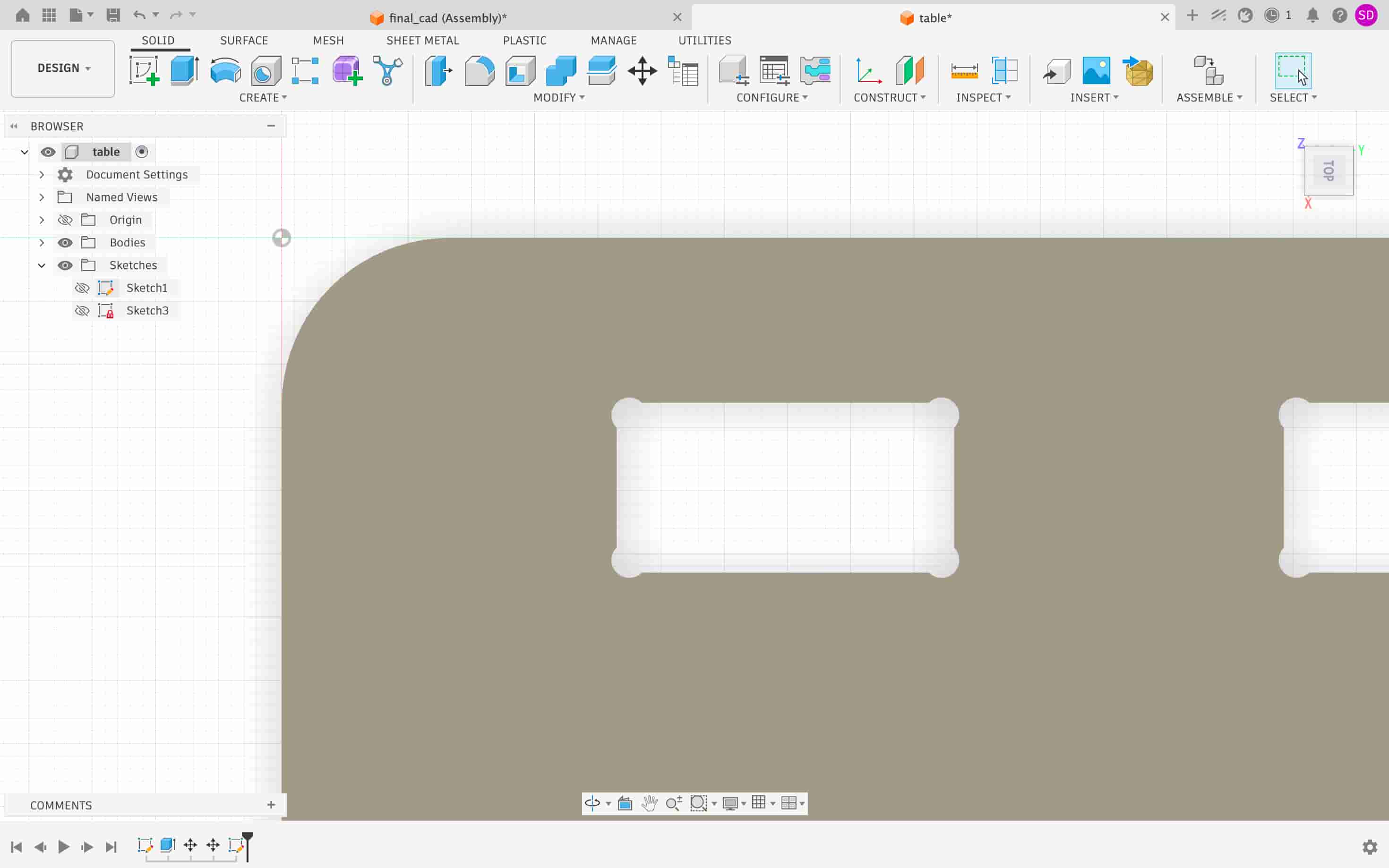
The coffee table was designed parametrically in Fusion 360. The dimensions of the table were controlled using user-defined variables, allowing the design to be easily adjusted if needed. To achieve a good press-fit assembly, a clearance of 0.3 mm was added between mating parts.
Since CNC routers use round cutting tools, they cannot produce perfectly sharp internal corners. To compensate for this limitation, dogbone fillets were added to all slot corners. The dogbone fillets were created with an approximately 2 mm radius, being sufficient to cut with a 4 mm diameter cutting tool, ensuring that the parts could fit together without interference.
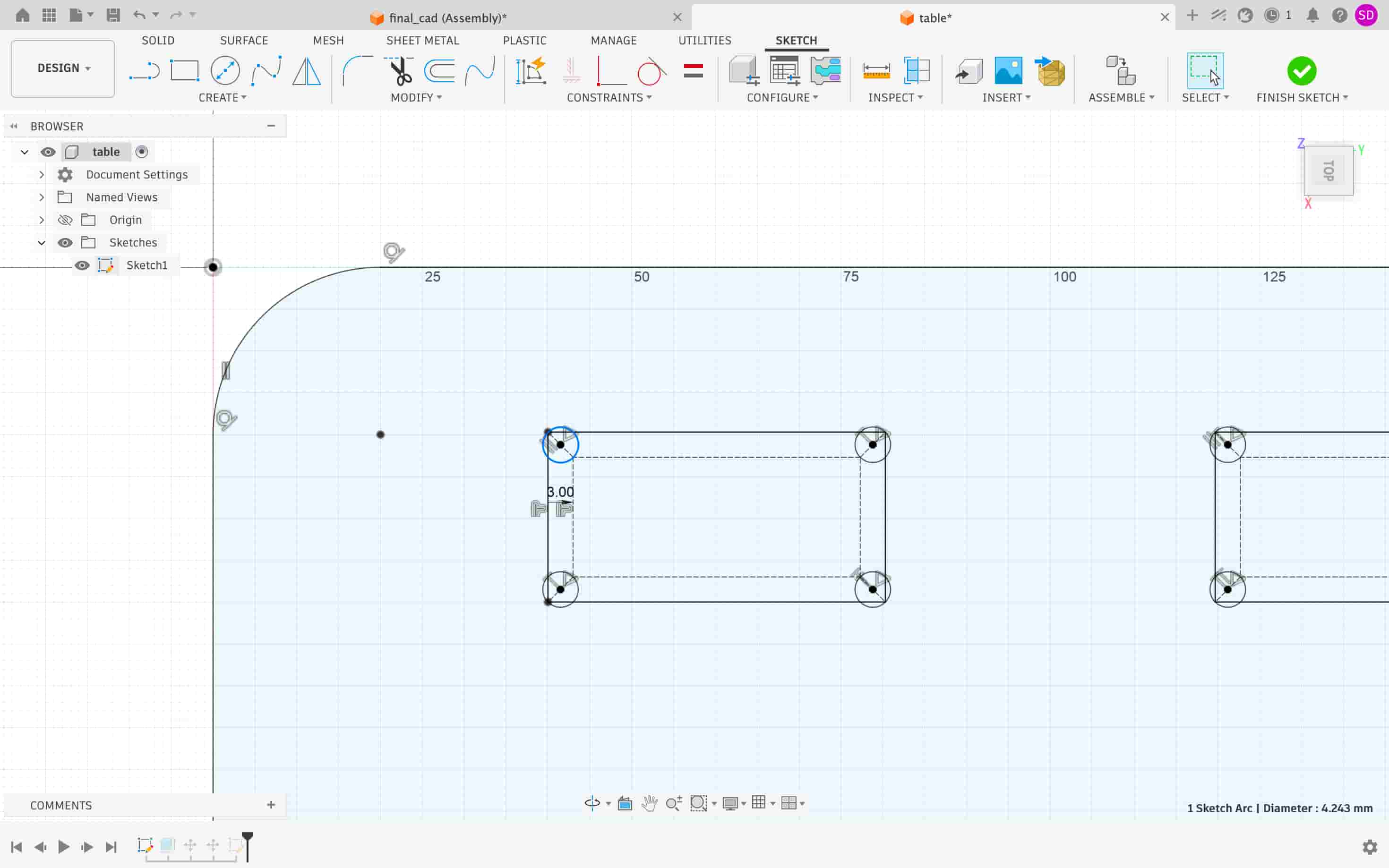
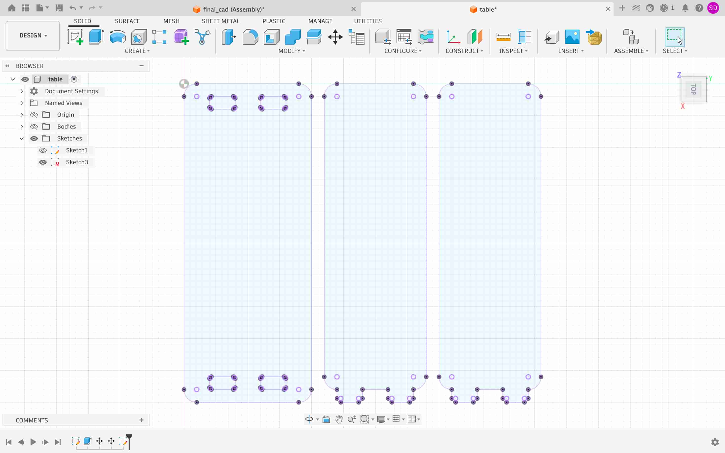
After completing the design, the outlines of all components were projected into a separate sketch and exported as a DXF file for CAM processing.
Toolpath Preparation in VCarve #
The DXF file was imported into VCarve, where the machining operations were prepared. When creating a new job, the material and machine setup parameters were defined as follows:
| Parameter | Value |
|---|---|
| Job Type | Single-sided |
| XY Datum Position | Bottom Left |
| Z Zero Position | Material Surface |
| Material Thickness | 20 mm |
| Safe Z Height | 20 mm |
These settings establish the work area and define how the machine references the material during machining.
VCarve was used to:
- Define the plywood sheet dimensions
- Configure the cutting tool
- Create profile machining operations
- Simulate the machining process
- Export machine-ready toolpaths for the CNC router
Tool Configuration #
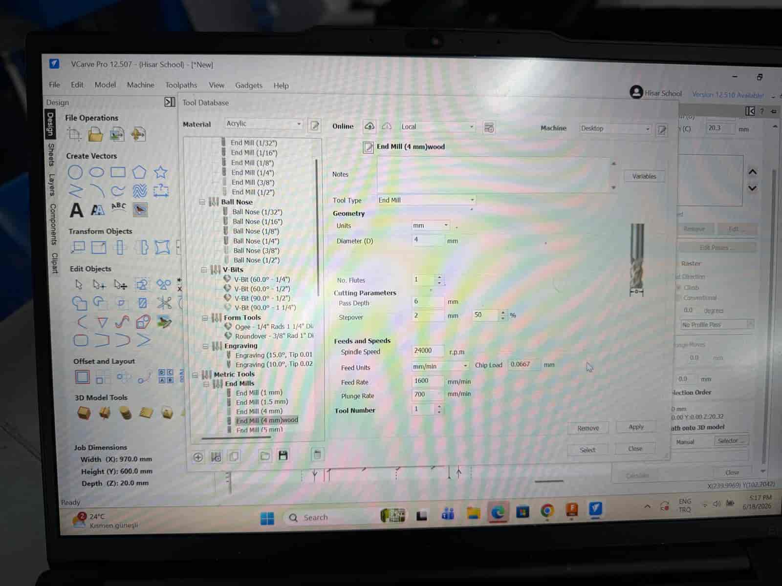
A flat end mill was selected for all cutting operations.
| Parameter | Value |
|---|---|
| Tool Type | Flat End Mill |
| Diameter | 4 mm |
| No. Flutes | 1 |
| Pass Depth | 6 mm |
| Stepover | 50% |
| Spindle Speed | 24000 RPM |
| Feed Rate | 1600 mm/min |
| Plunge Rate | 700 mm/min |
| Parameter | Value |
|---|---|
| Tool Type | Flat End Mill |
| Diameter | 6 mm |
| No. Flutes | 1 |
| Pass Depth | 10 mm |
| Stepover | 40% |
| Spindle Speed | 24000 RPM |
| Feed Rate | 2000 mm/min |
| Plunge Rate | 1000 mm/min |
The selected parameters provided a balance between cutting efficiency and surface quality for the plywood material.
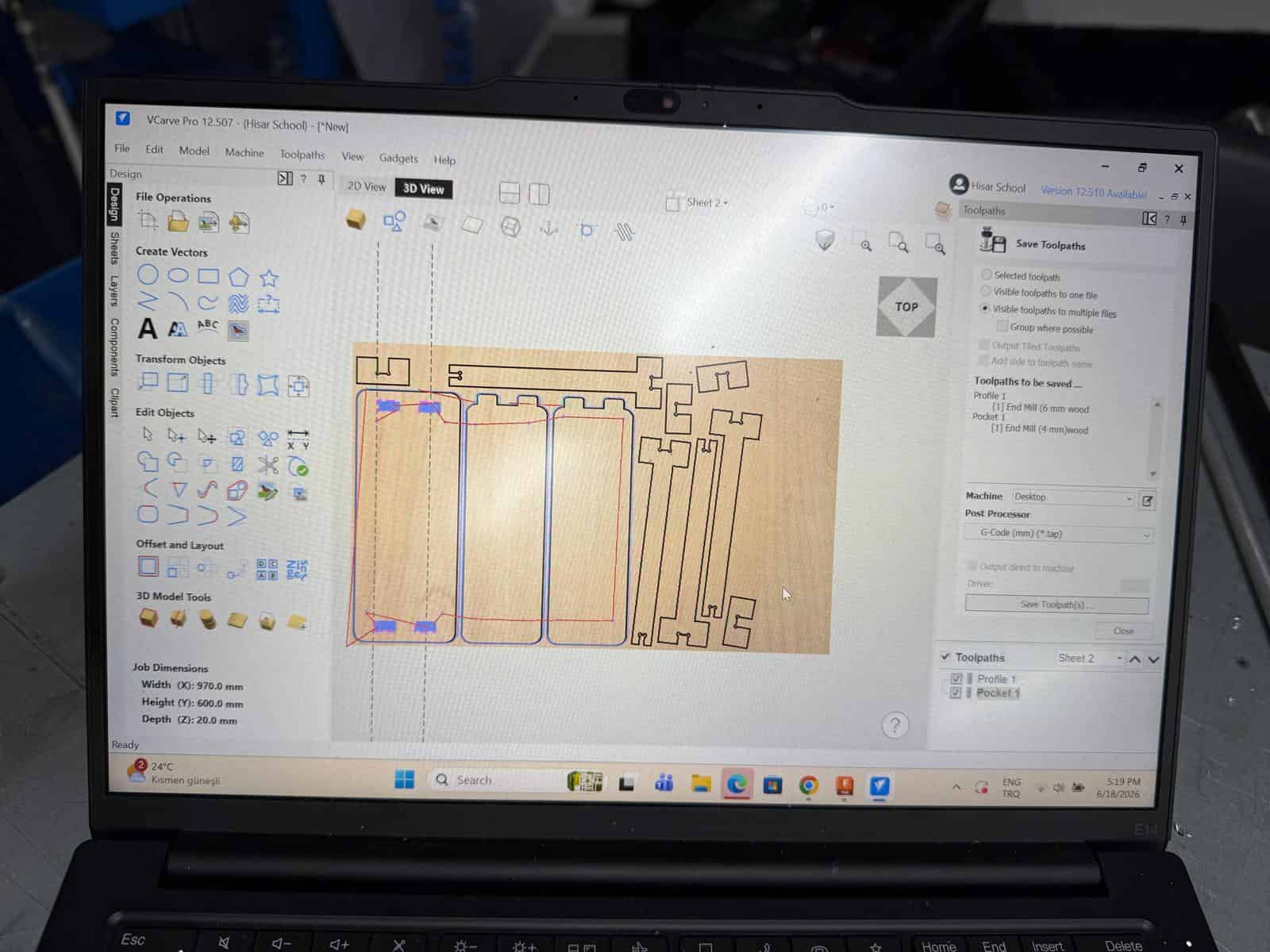
Toolpaths #
The components were machined using a combination of pocket and profile toolpaths. Pocket toolpaths were used to remove material from internal features, while profile toolpaths were used to cut the outlines of the parts and separate them from the plywood sheet.
Different profile directions were assigned depending on the geometry being cut:
| Geometry | Toolpath Type |
|---|---|
| Slots and internal features | Inside Pocket |
| External part contours | Outside Profile |
Using inside profiles for slots preserves the correct opening dimensions, while outside profiles ensure the external dimensions of the parts remain accurate.
Cut Depth Settings #
To guarantee complete separation of the parts from the plywood sheet, the cutting depth was set slightly deeper than the material thickness. The 0.5 mm allows the cutter to pass completely through the material even if there are slight variations in board thickness or machine leveling.
| Parameter | Value |
|---|---|
| Material Thickness | 20 mm |
| Cut Depth | 20.5 mm |
Ramp Entry #
To reduce stress on both the cutting tool and the machine, a ramp entry strategy was used instead of a direct plunge.
| Parameter | Value |
|---|---|
| Ramp Type | Smooth Ramp |
| Ramp Distance | 15 mm |
With this approach, the tool gradually enters the material, resulting in smoother cutting and reduced tool wear.
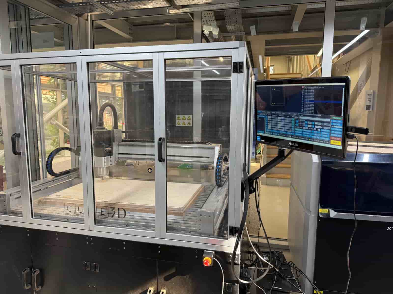
CNC Machine Preparation #
For this week’s assignment, I used Derinmotion Cube3D, a CNC router manufactured in Türkiye.
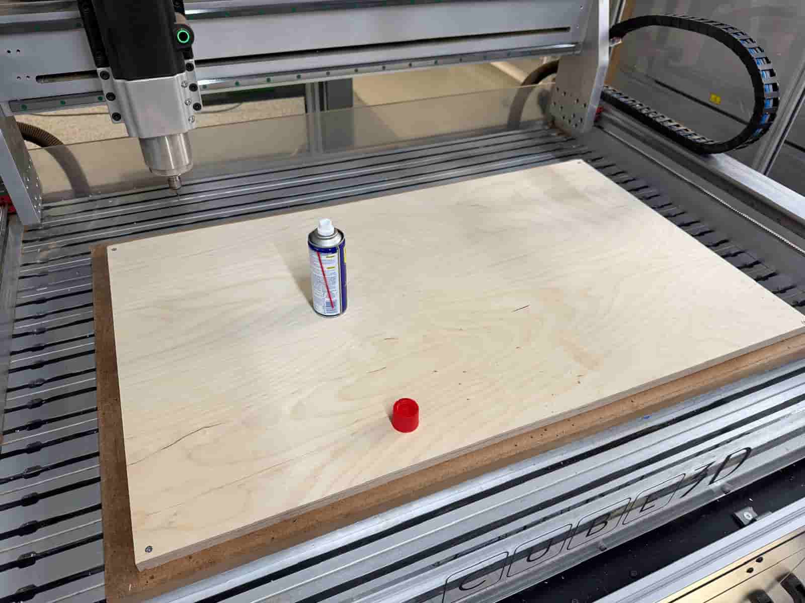
Before machining, the machine bed was cleaned and prepared. Proper preparation helps ensure:
- Accurate material positioning
- Reliable workholding
- Improved machining quality
- Safer operation
The plywood sheet was securely fixed to the machine bed before cutting began.
Safety Considerations #
Operating a CNC router requires attention to safety at all times.
The following precautions were observed during machining:
- Wear hearing protection
- Keep hands away from moving components
- Never leave the machine unattended while cutting
- Verify that the material is fixed
- Review all toolpaths before starting the job
Setting the Work Origin #
Before machining, the machine coordinate system was established by defining:
- X-axis origin
- Y-axis origin
- Z-axis origin
Accurately setting the work origin ensures that the machine follows the generated toolpaths in the correct location on the material.
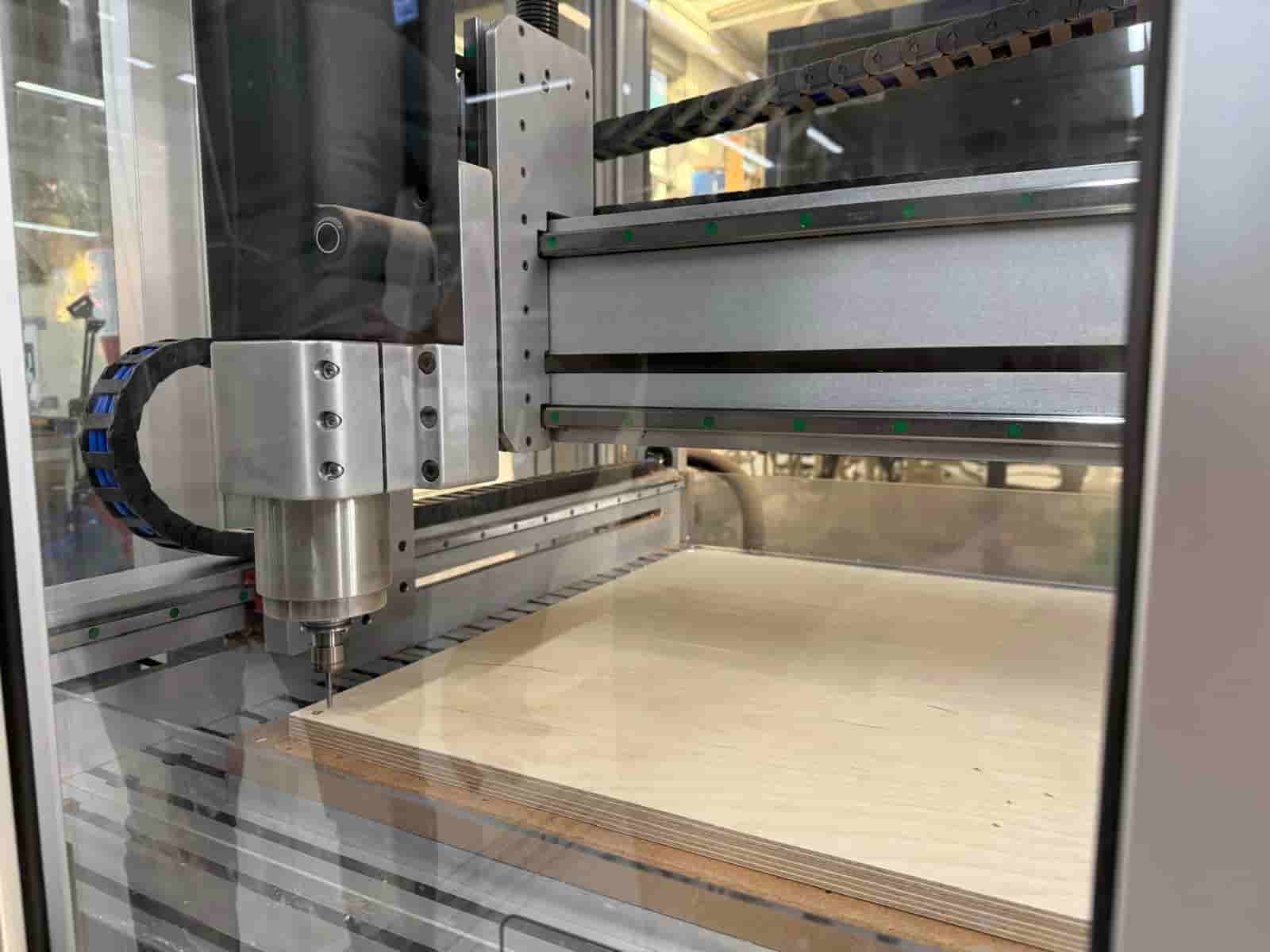
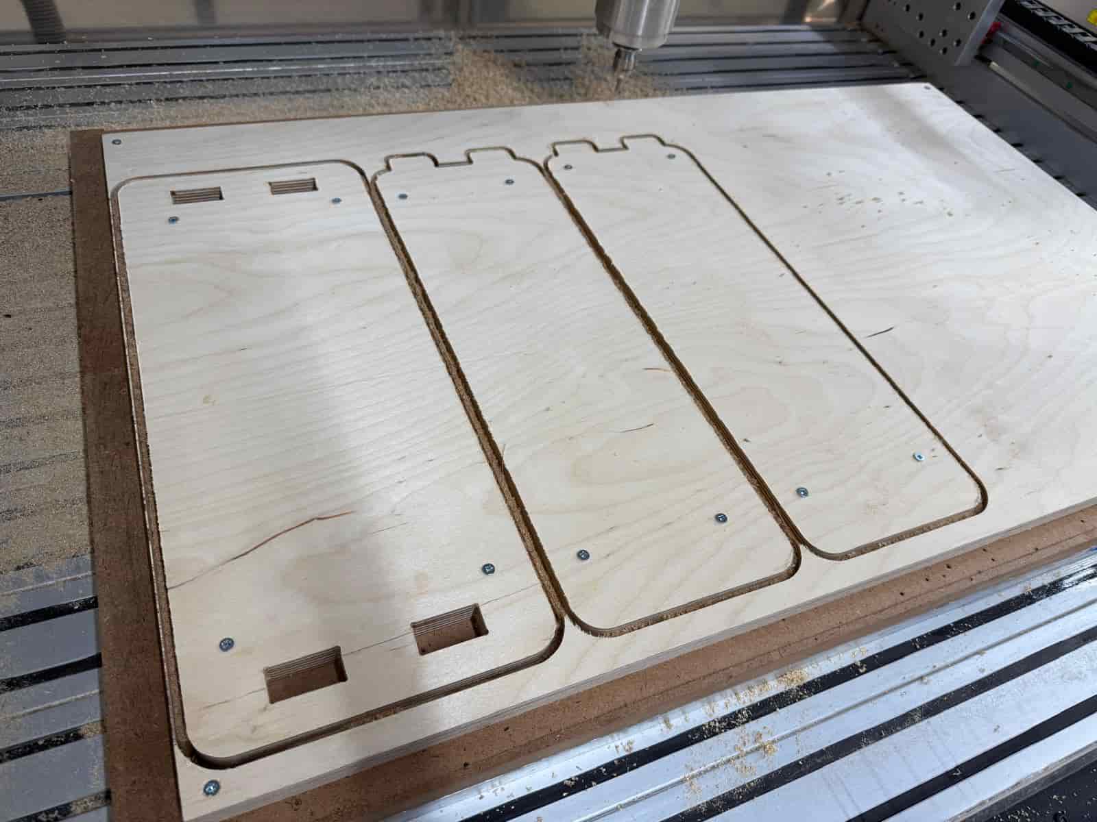
CNC Machining #
After the machine setup was completed and the work coordinates were established, the machining process was started.
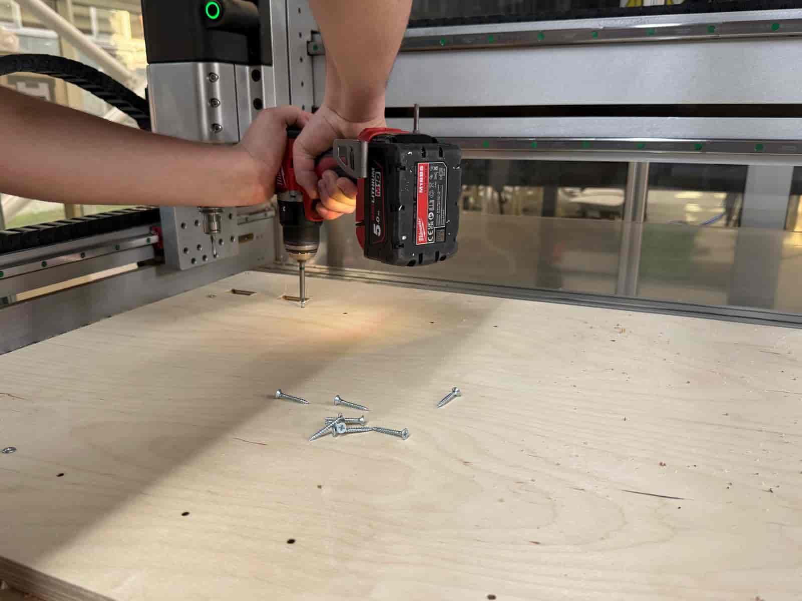
After the pocket toolpath is completed, new screws were added to fix the final machined pieces on the machine bed. Then the end mill is changed to 6mm and the profile process was started.
The CNC router followed the generated toolpaths to cut all coffee table components from the plywood sheet. Once the cutting process was finished, the parts were removed from the machine bed, cleaned, and assembled using the press-fit joints designed in the CAD model.
The completed assembly resulted in a functional coffee table for the lab break area.
Files: