Week 11 - Networking and Communications #
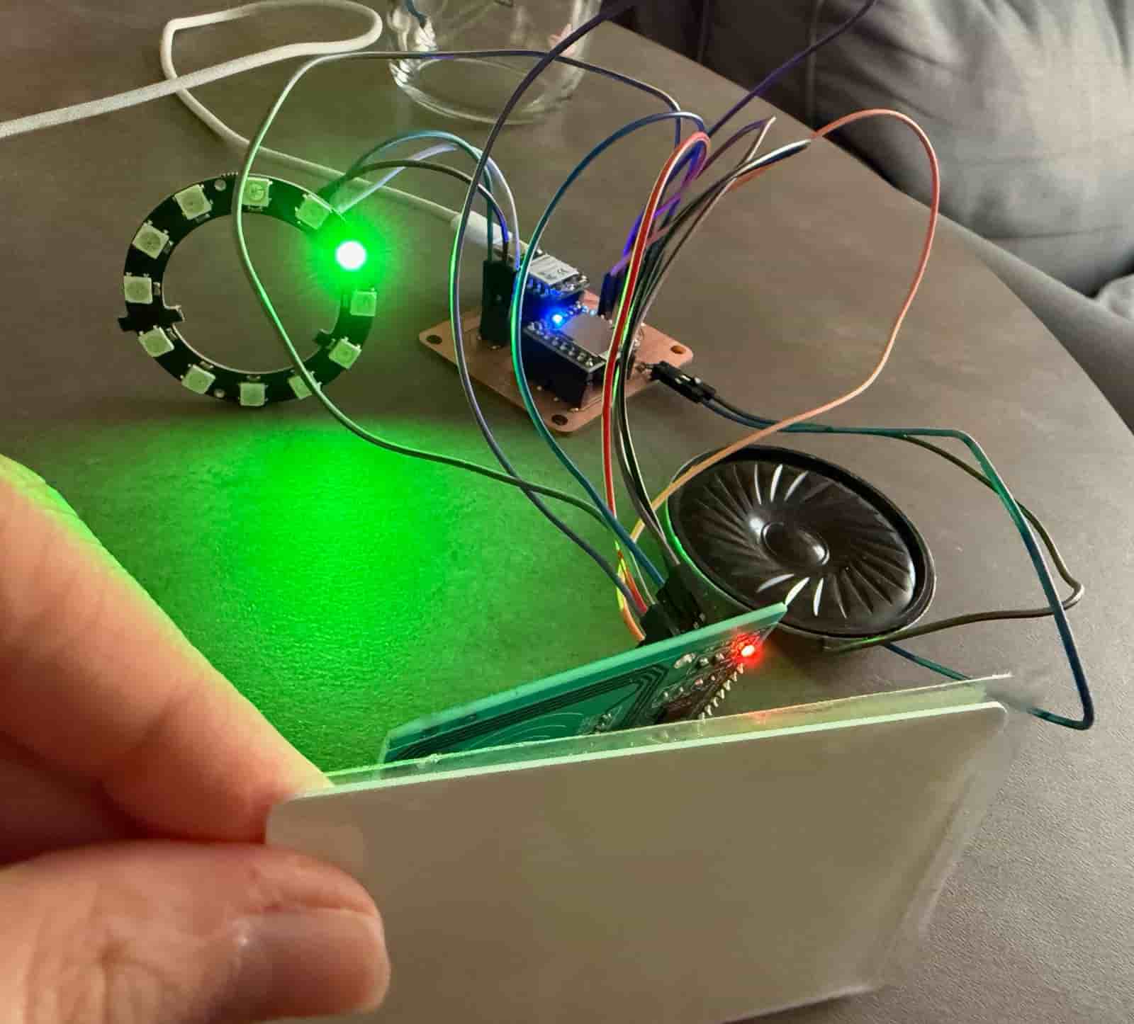
Hero Shot: #
TL;DR #
I connected a WS2812B NeoPixel Ring 12 to my custom PCB and programmed it using a single-wire serial communication protocol. Each LED acts as an individually addressable node on a shared communication bus, allowing the microcontroller to control every LED independently with different colors and timing patterns.
Group Assignment #
Link to this week’s group assignment
Communicating with a Local Output Device via Web Browser #
The goal of this week was to design and build a wireless network node capable of communicating with a client device over Wi-Fi while controlling a local output device. So for this assignment, I used an ESP32-C3 as an HTTP server, allowing a web browser to send commands that trigger the NeoPixel LED ring connected to the microcontroller.
The ESP32-C3 connects to a Wi-Fi network using the provided SSID and password. Once connected, it is assigned an IP address, which serves as its network address. The board hosts a simple web page that can be accessed from any device connected to the same network.
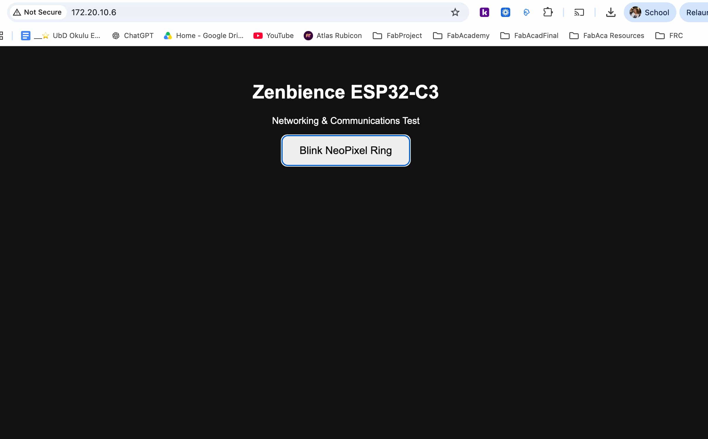
The web page contains a single button that sends an HTTP request to the ESP32-C3. Upon receiving the request, the ESP32-C3 blinks the connected NeoPixel ring three times, demonstrating successful communication between the client and the embedded node.
The communication flow is as follows:
Laptop / Phone
       |
   HTTP Request
       |
   Wi-Fi Network
       |
   ESP32-C3
       |
 NeoPixel Ring
For Wifi communication and the HTTP server, I included the following libraries:
#include <WiFi.h>
#include <WebServer.h>
With the following function, the ESP32-C3 connects to the specified wireless network using the Wi-Fi credentials (the SSID and the password):
WiFi.begin(ssid, password);
The connection status is continuously checked until the board successfully joins the network. Once connected, the assigned IP address is printed to the Serial Monitor.
Serial.println(WiFi.localIP());
An HTTP server is created on port 80. Two routes are registered:
/serves the HTML page./blinkexecutes the NeoPixel blinking function.
server.on("/", handleRoot);
server.on("/blink", blinkRing);
The HTML page contains a button that sends a request using JavaScript’s fetch() function.
<button onclick="fetch('/blink')">
When the request reaches the ESP32-C3, the handleBlink() function calls blinkRing(), which turns all sixteen LEDs green, switches them off and on three times.
This video shows the NeoPixel ring test that is triggered via a web browser:
I used ChatGPT for guidance while determining the HTTP server commands and route handling needed to communicate with the ESP32-C3. The use of AI was only to clarify the appropriate functions for establishing the HTTP connection. The implementation, testing, and integration with the NeoPixel ring were completed by me.
Files: