Week 15 - System Integration #
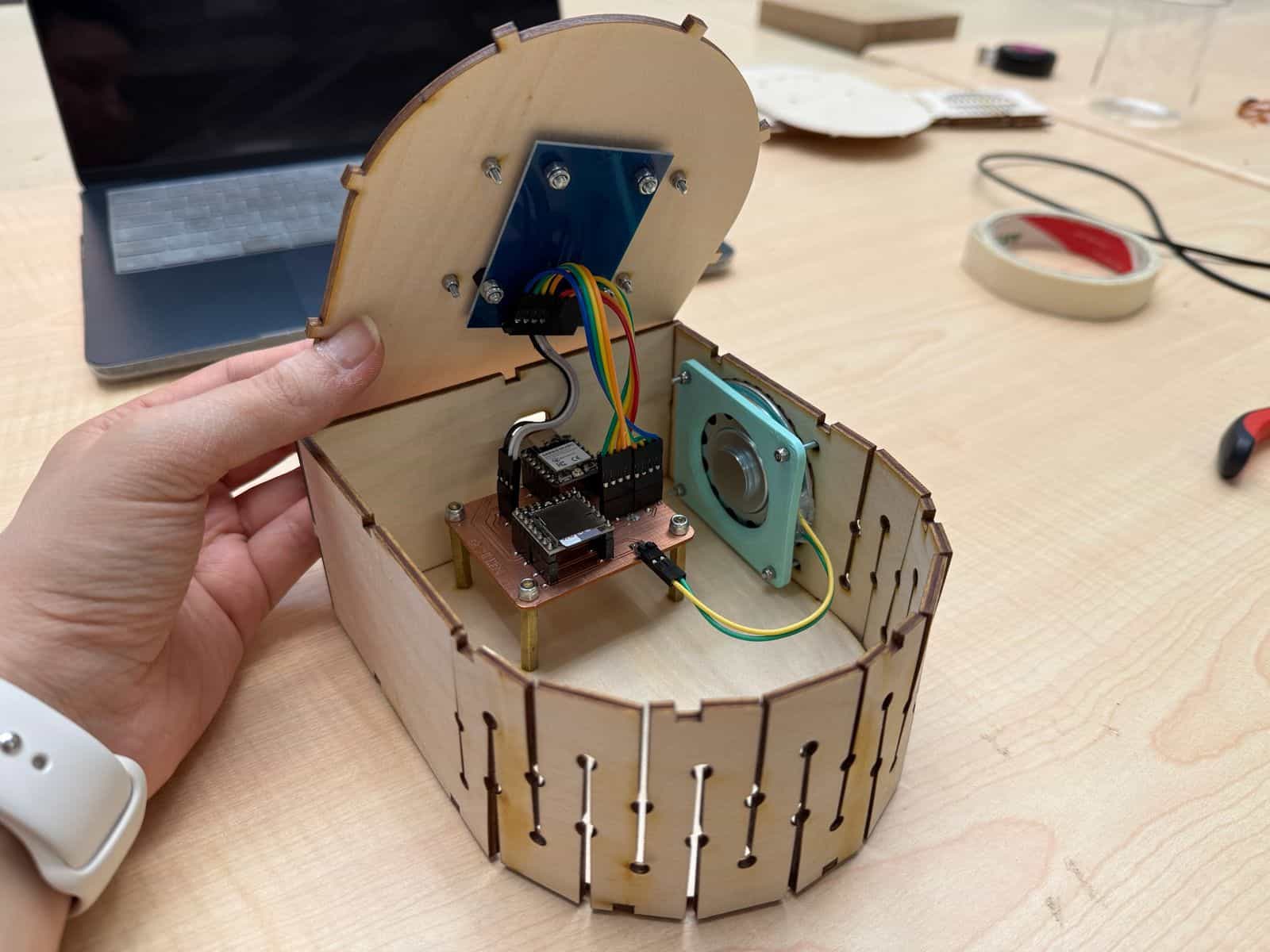
Hero Shot: #
TL;DR #
For this week’s assignment, I made a plan for the system integration and assembly of my final project and created CAD sketches on how it will look like. I used the necessary skills to ensure my system looks like a finished project rather than an early stage prototype.
CAD Drawings and System Integration Plan #
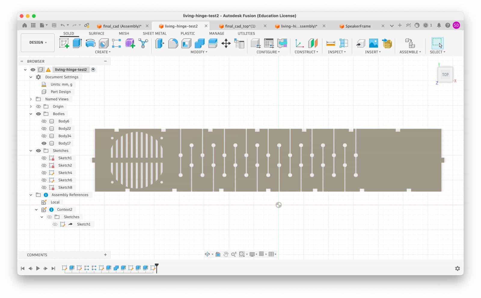
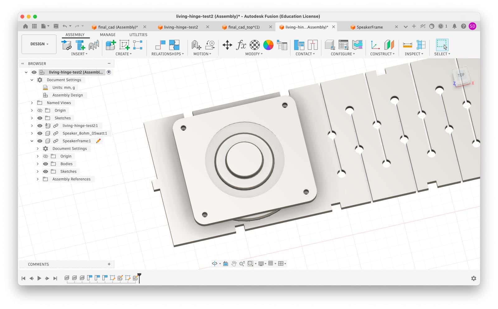
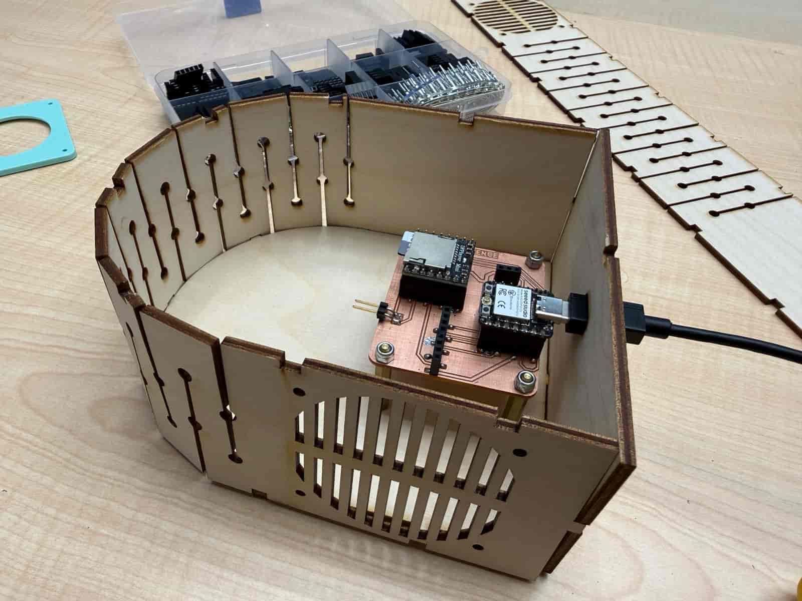
I created the final design of my final project, Zenbience. For the packaging I decided to use laser cutting with 3mm basswood plywood. Around the enclosure, I designed a living hinge. The living hinge has joints around it to ensure the enclosure can be tightly snap-fit. The joints were mathematically calculated with the top, base, and back covers.
I used the 3D model of my PCB that I exported from KiCad. Since I want to use a wall adapter to power my desk device, I had to leave a small slot for the type-C connection to the XIAO SEEED ESP32-C3. Placing the PCB board directly on the base of the plywood would not be very good and stable. So, I used 4 20mm standoff spacers and 4 M3 fiber nuts along with 4 M3 * 10mm bolts to secure the PCB tightly. As a result, the PCB cannot move freely inside my enclosure.
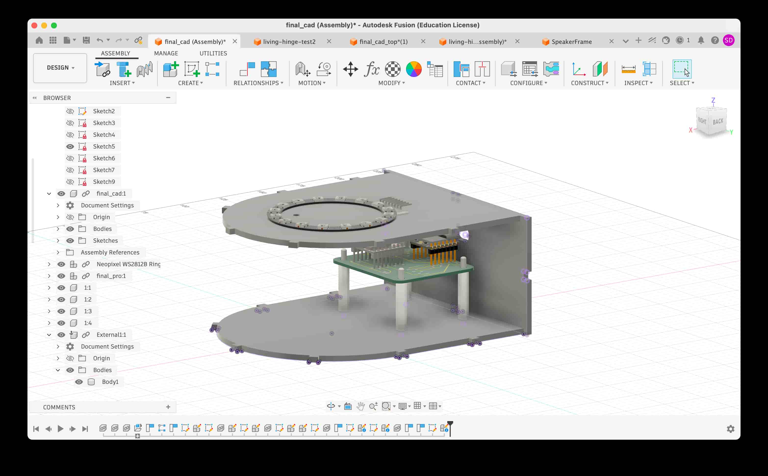
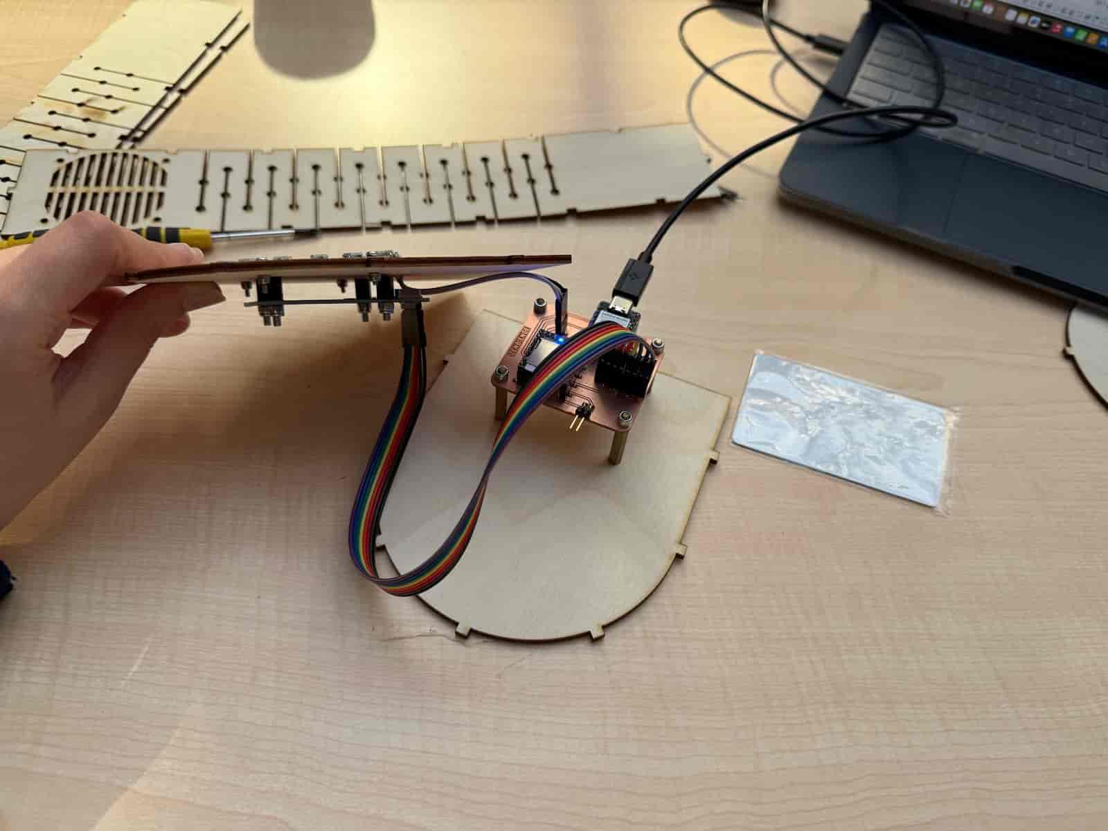
On the top cover, I wanted to secure both the neopixel and the RFID reader. The neopixel has to be seen from the outside but the RFID reader can be under the cover. Before commiting to the design, I also tested the RFID reader to see how much distance it can read from. My tests were fruitful (it could read under about 15mm of plywood!), giving me the choice to place it under the cover. I also added a slot on the top cover for the cables of the neopixel.
I laser cut the parts, gathered the nuts and bolts, and assembled. After some iterations, I was successful.
For more detail, please refer to my Final Project documentation page.
Files: