Week 12 - Machine Building #
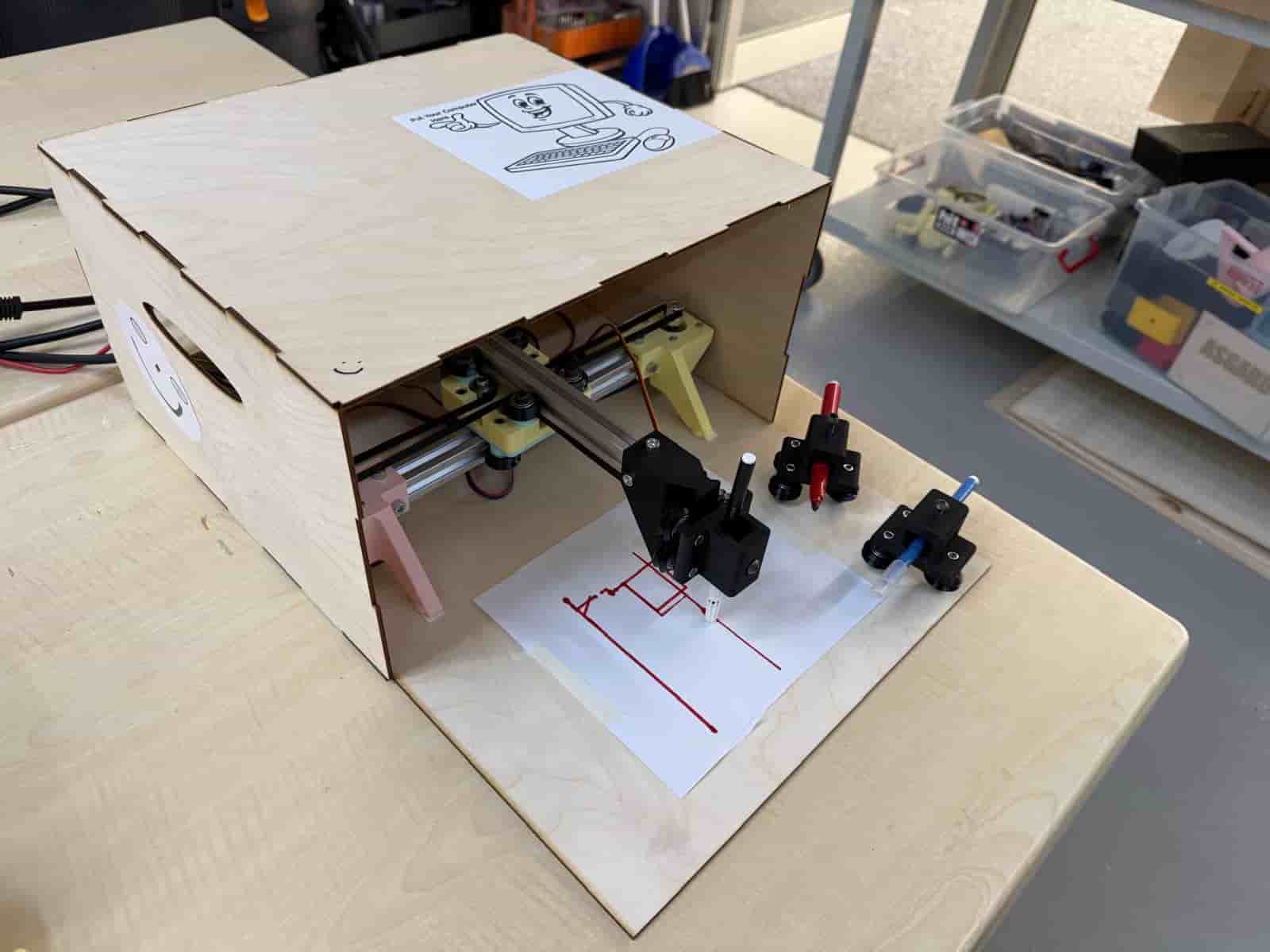
Hero Shot: #
TL;DR #
This week we collaborated with the Aalto FabLab as the HAAC (Hisar Aalto Cooperation) team for the machine building project. We decided to build a plotter machine, which we named the HAAC Plotter. My main task was to gather all the mechanical parts required and then to assemble the machine using the guides of the Blot Plotter by HackClub.
Links and Resources for HAAC Plotter #
This week’s group assignment page
Hisar FabLab Machine Week documentation page
Hisar FabLab Machine Week resources and demos
HAAC Plotter Control Dashboard
Ideation #
Our first plan was to build an EDM machine based on the CoreXYZ principle. Due to some unforeseen circumstances, some members had limited availability. Therefore, we decided make a change of plans and decided to build a pen plotter. The Blot Plotter by HackClub offered an open guide of the assembly.
We had daily meetings and individual tasks that we kept track on a Miro board. We also created a Google Drive for all the media files. My task was to assemble the plotter.
Assembly #
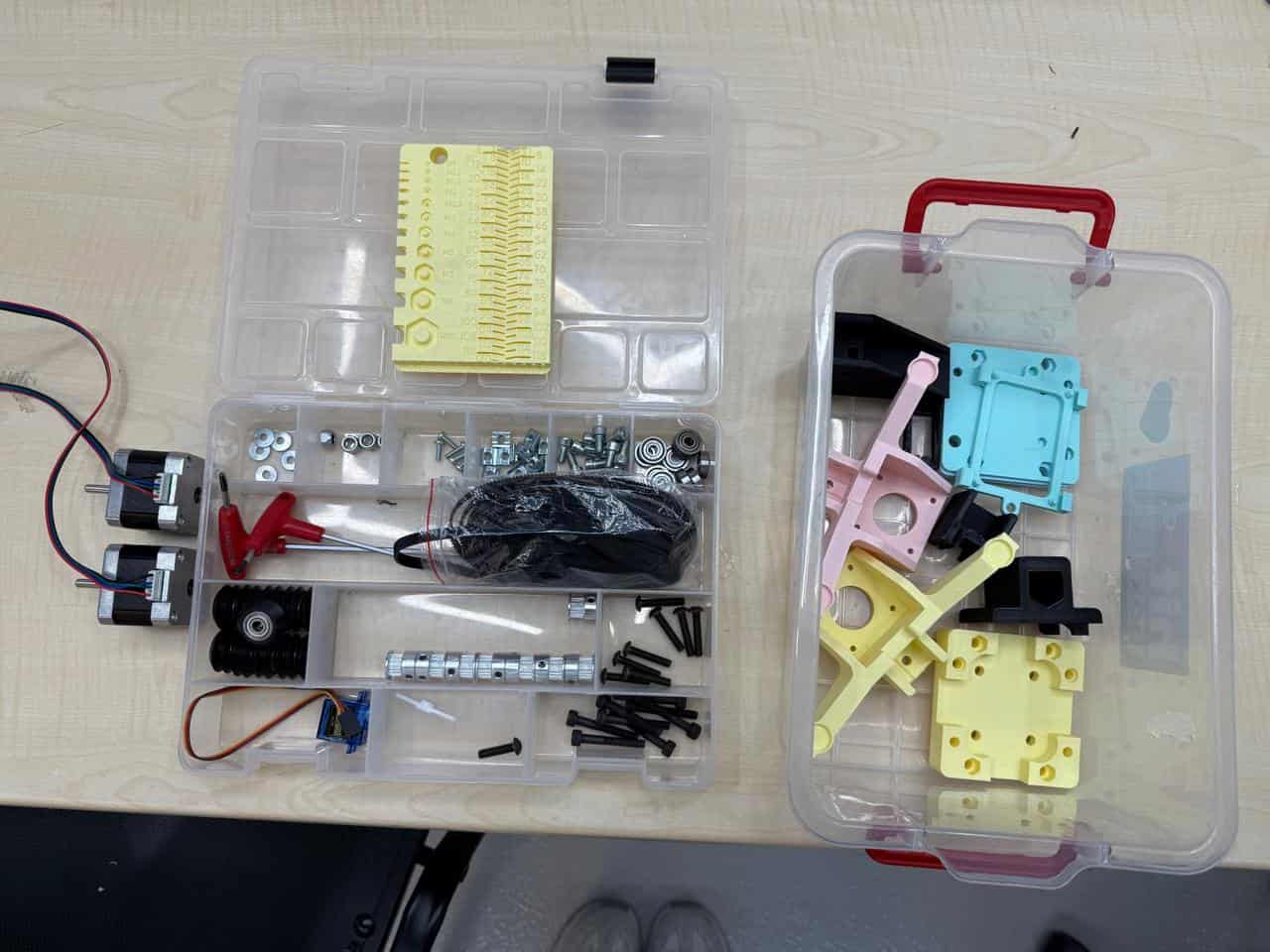
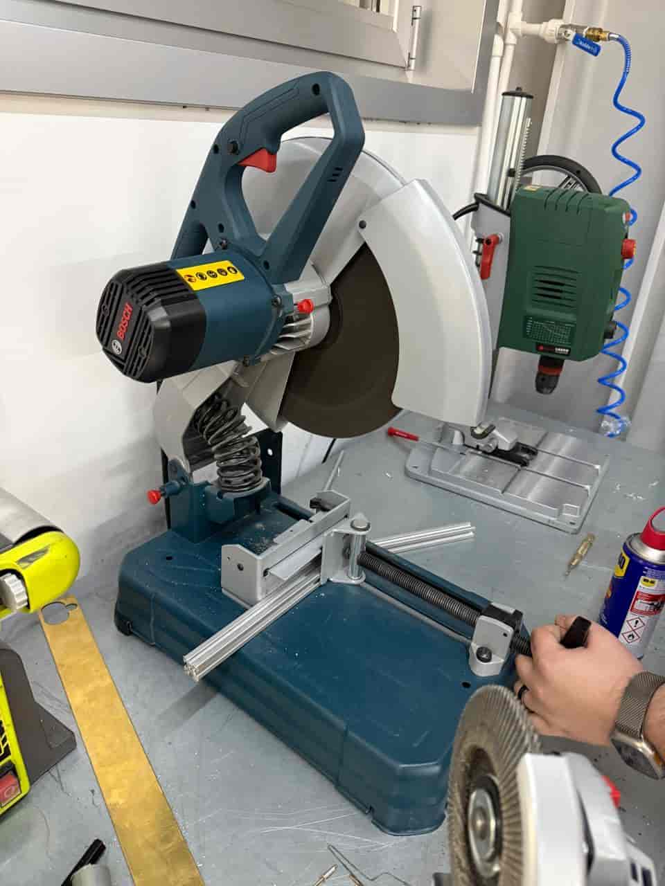
I started by gathering all of our tools and parts. The tools and parts can be found in this guide. I 3d printed the design files of the Blot machine and also designed some spacers required for the connections since we did not have aluminum spacers.
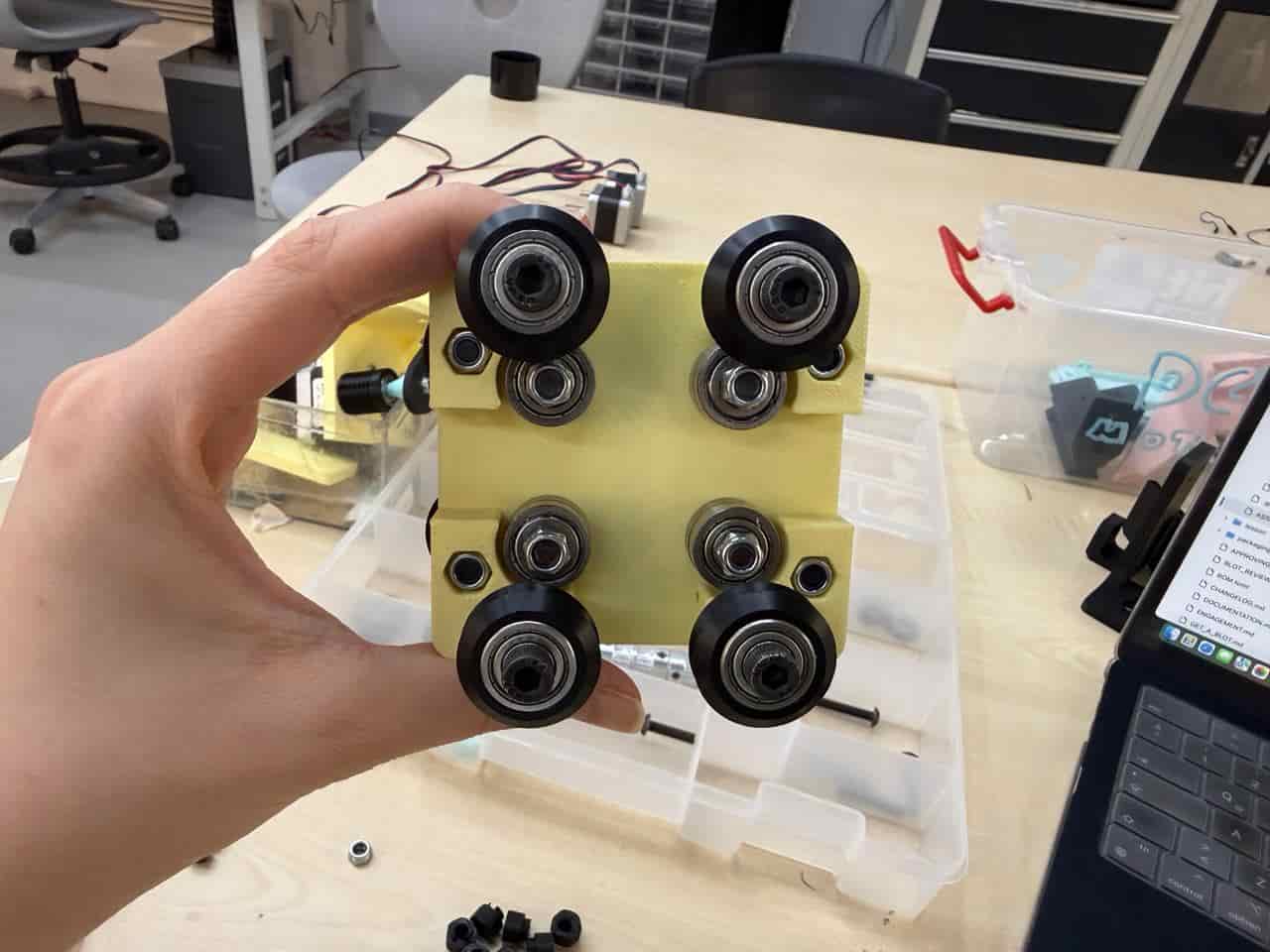
I started off by assembling the carriage. For the carriage I needed the following parts:
- 4 x M5x25 Button Cap Screw
- 8 x M5x35 Button Cap Screw
- 8 x 625zz V-Wheel
- 8 x 5x16x5mm flanged bearing
- 4 x 6mm tall x 8mm OD x M5 inner Spacer
- 12 x M5 Nut
- 4 x 6mm tall x M5 inner Eccentric Spacer
- 4 x 1mm tall x 10mm OD x M5 inner Spacer
- 1 x Carriage
- 1 x Carriage Plate
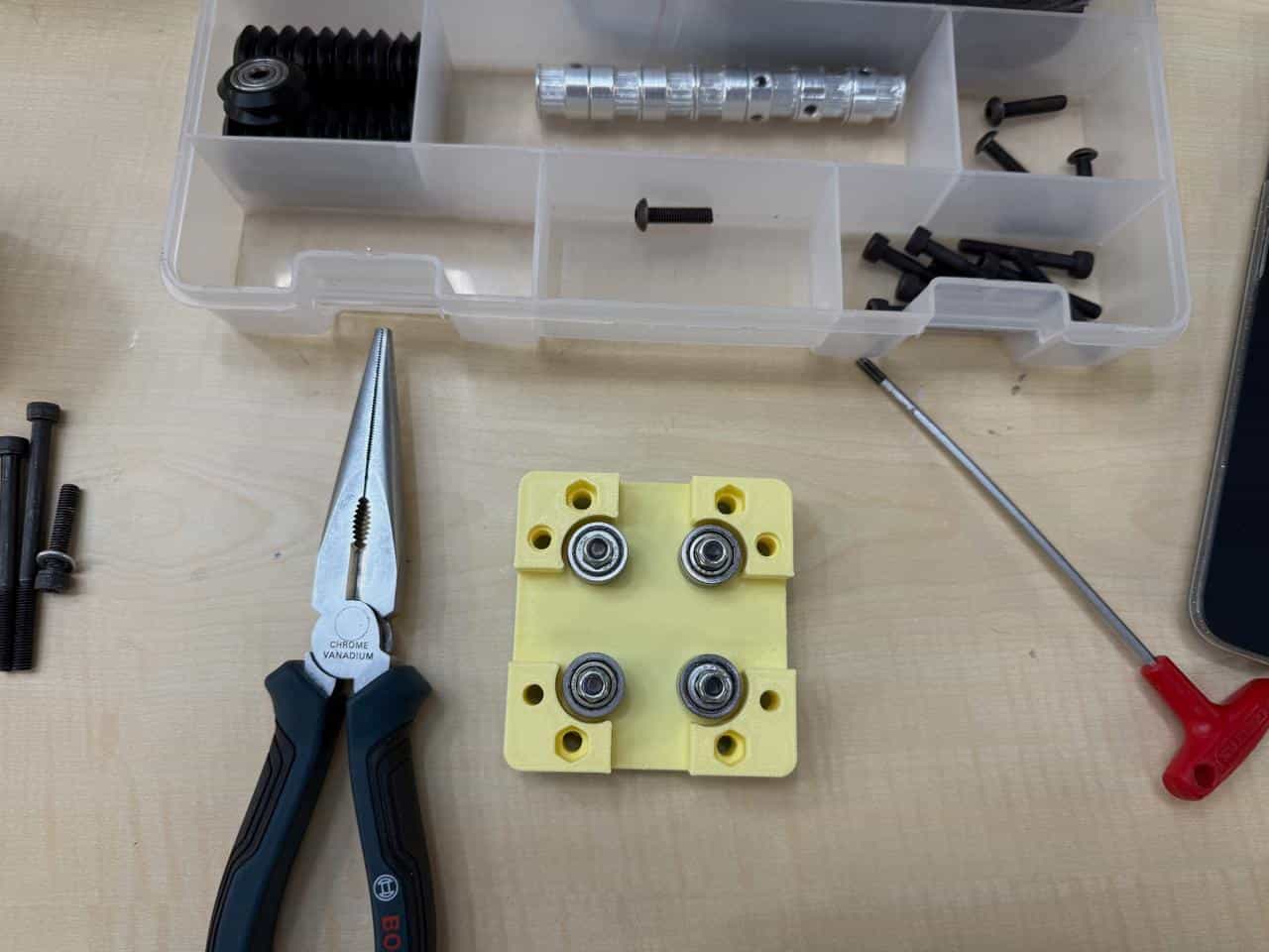
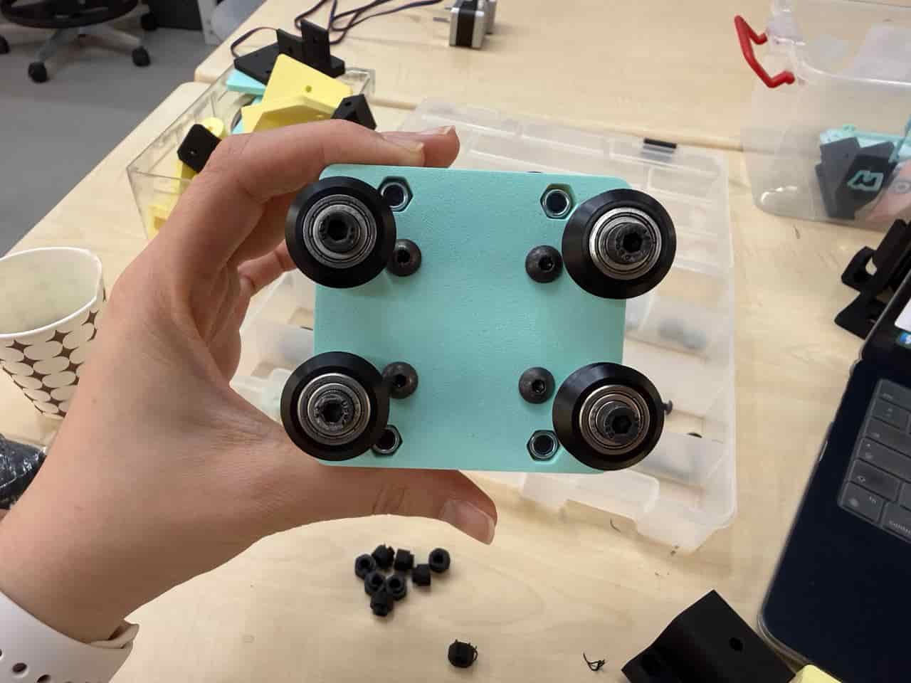
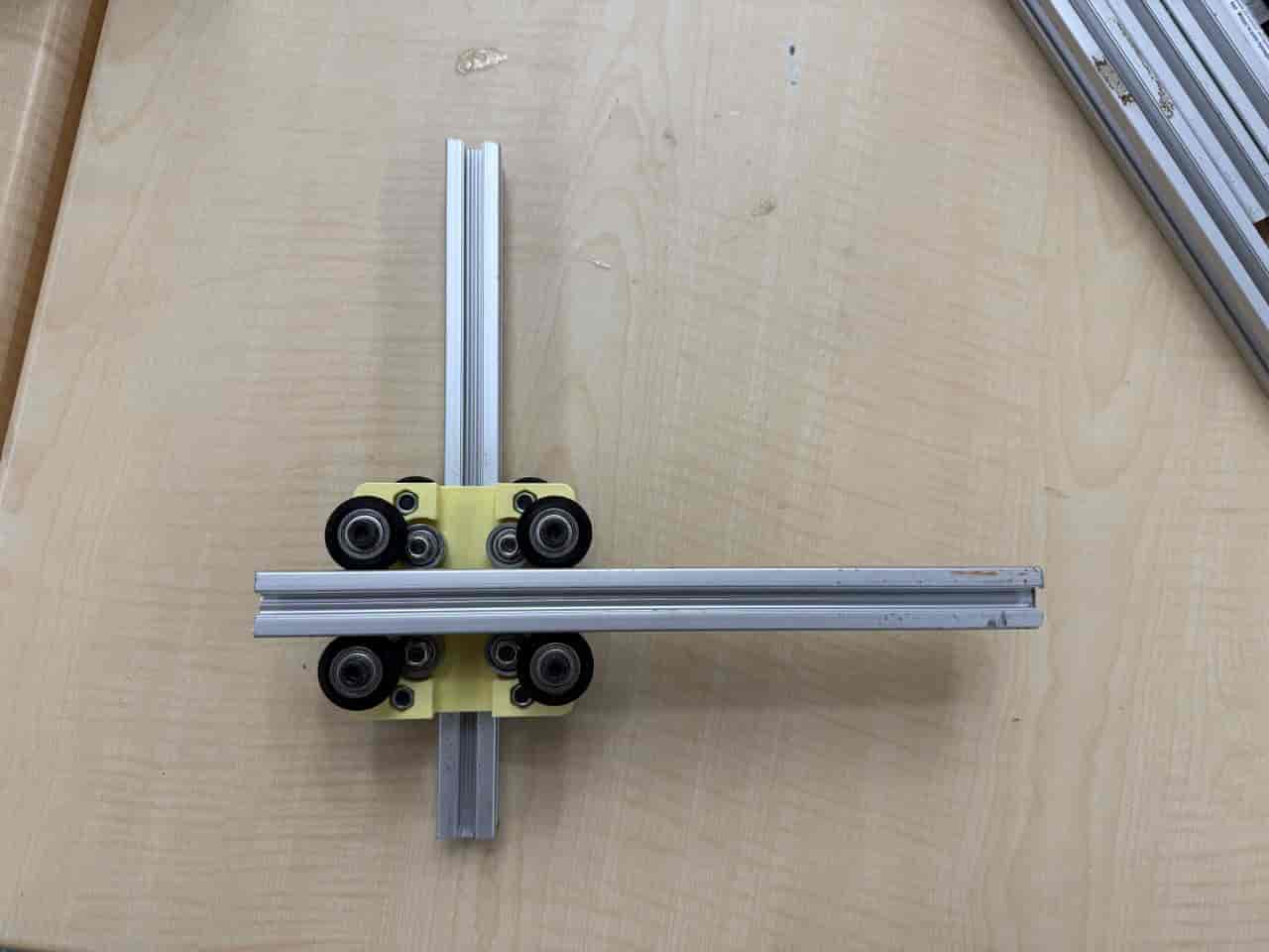
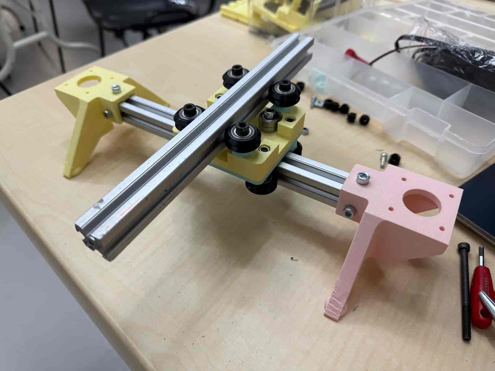
The carriage should look like this when finished:
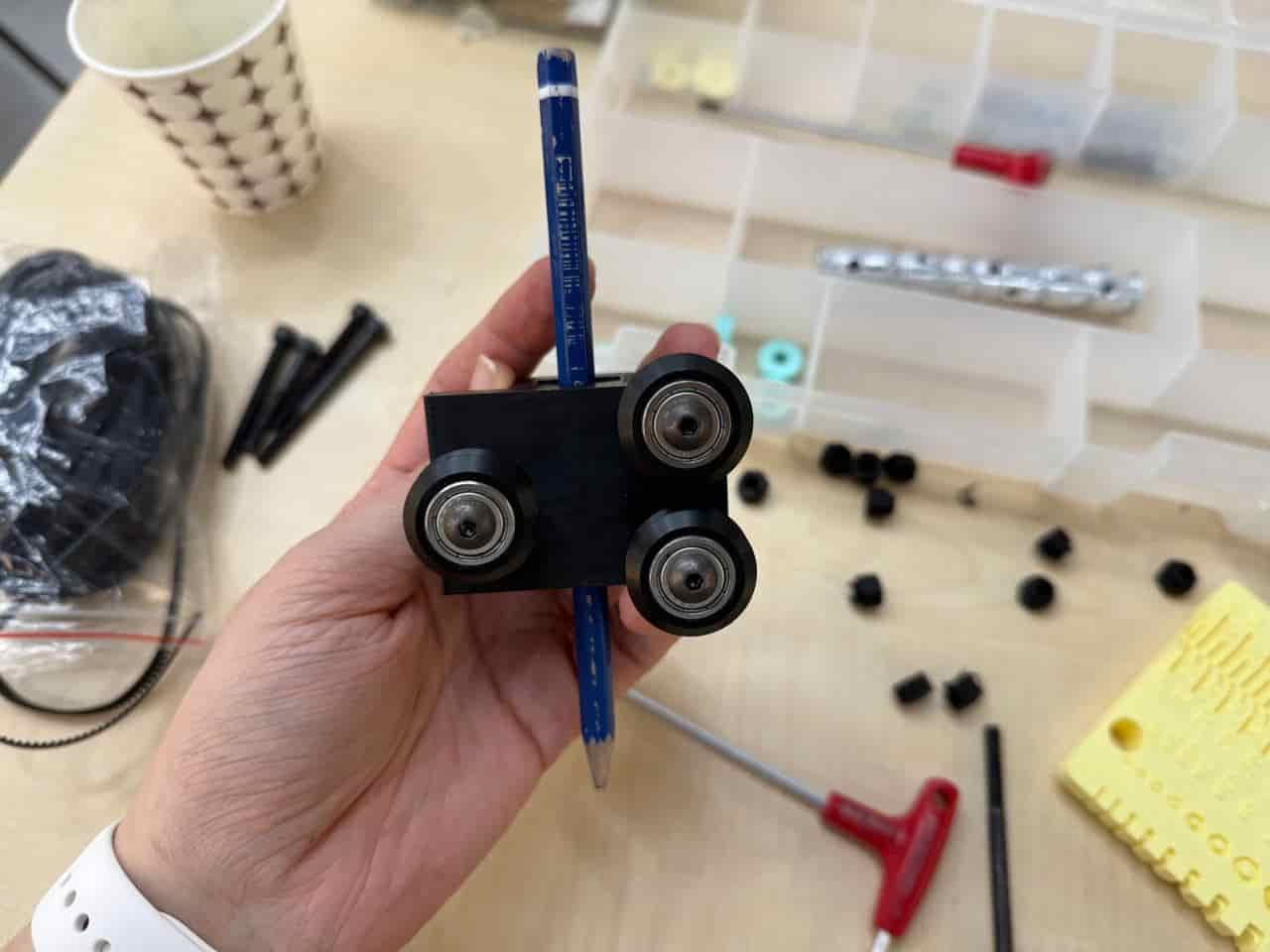
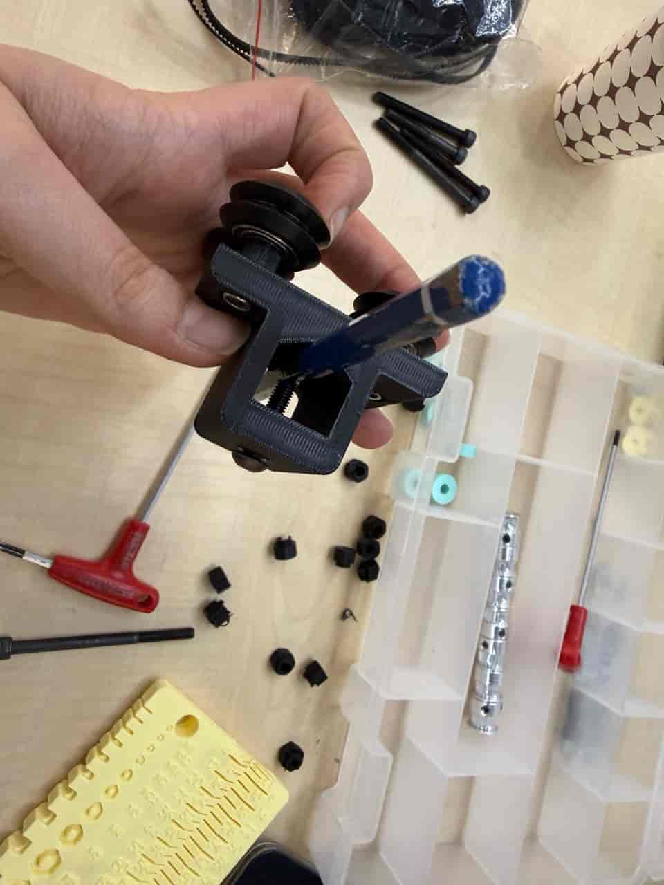
For the rail that holds the tool holder, the following parts are required:
- 1 x M5x25 Button Cap Screw
- 1 x M5 Nut
- 1 x 1mm tall x 10mm OD x M5 inner Aluminum Spacer
- 1 x Printed Rail
- 2 x 5x16x5mm flanged bearing
- 1 x Servo (25mm cable) + arm
I attached two bearings on the “Printed Rail” part.
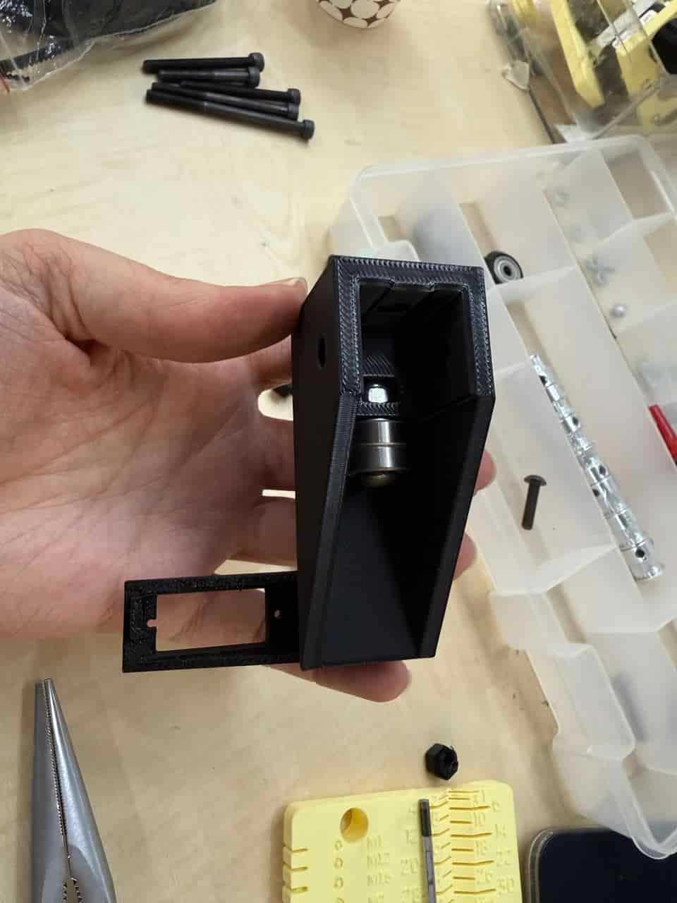
Then, I assembled the toolholder. The following parts are needed for the tool holder:
- 3 x M5x25 Button Cap Screw
- 4 x M5 Nut
- 1 x M5x20, knurled cylinder head
- 1 x Tool Head
- 1 x 6mm tall x M5 inner Eccentric Spacer
- 3 x 625zz V-Wheel
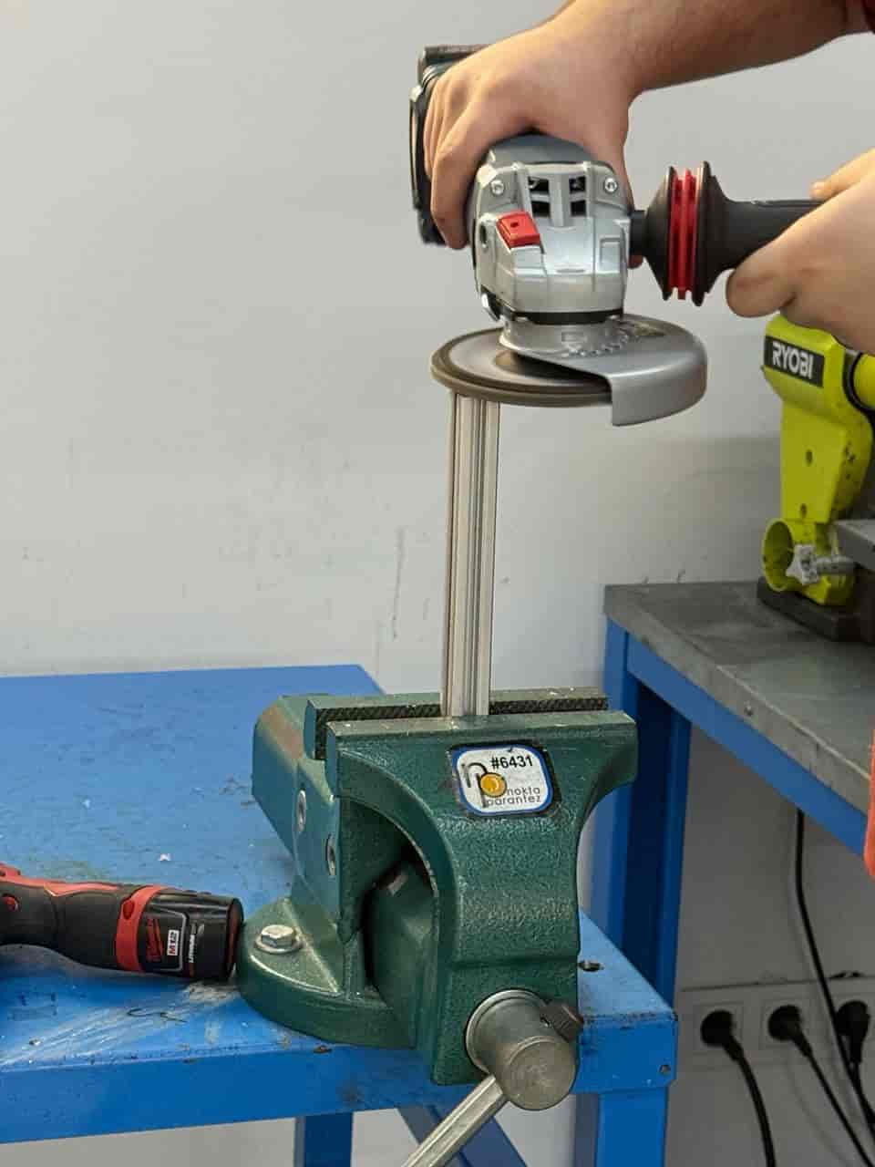
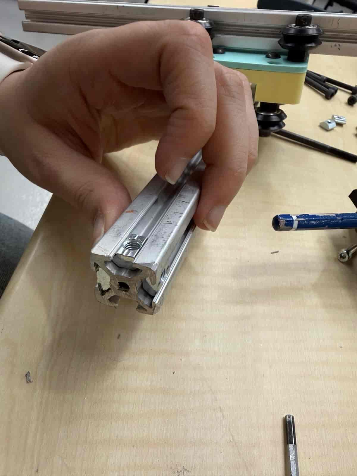
After that, we cut 2 aluminum extrusions into 25cm in length pieces.
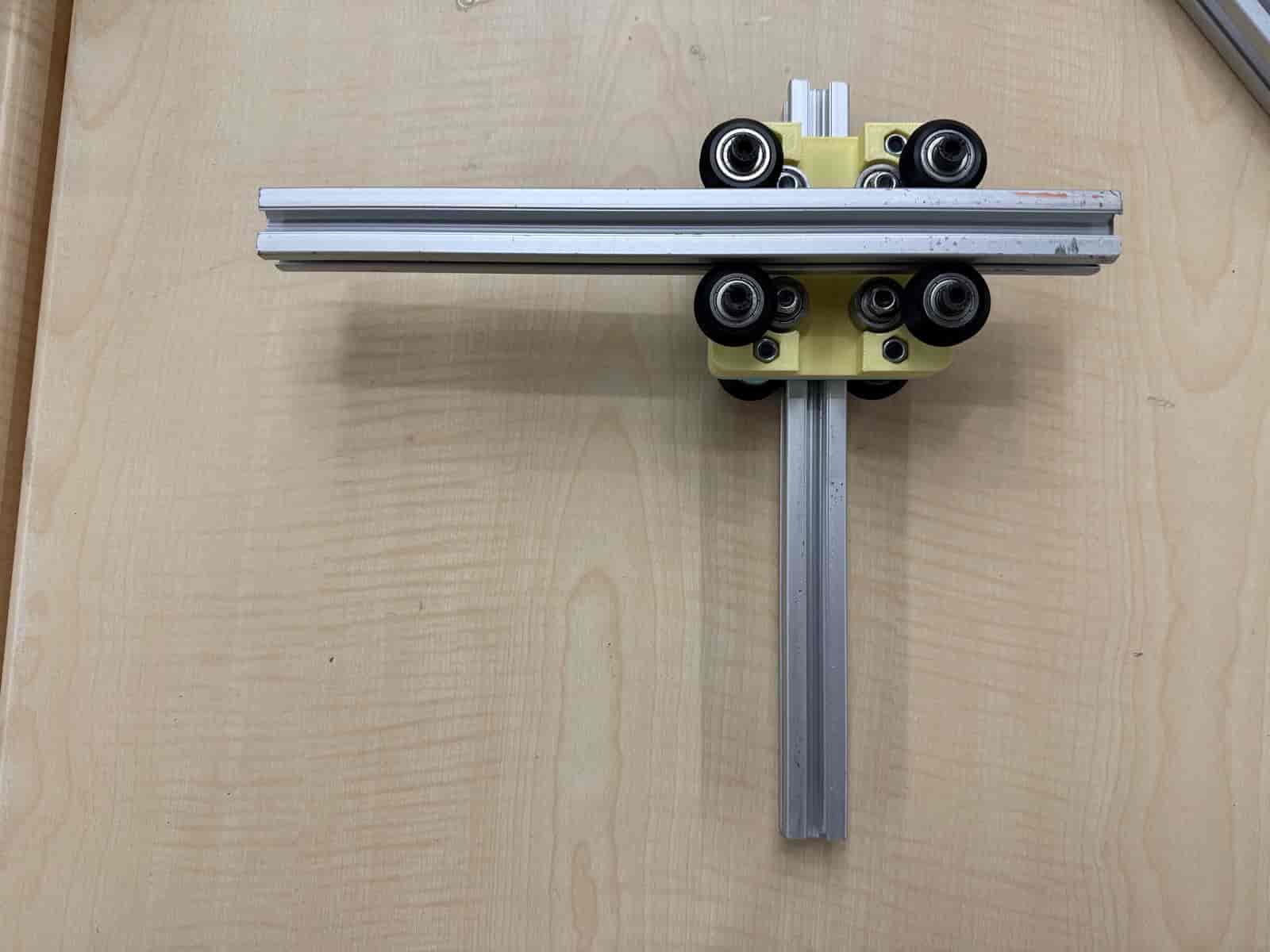
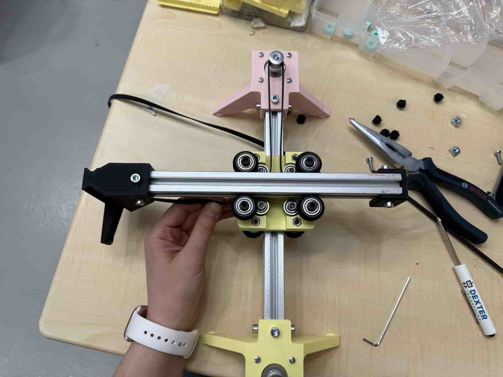
Then, I tested the carriage and extrusions.
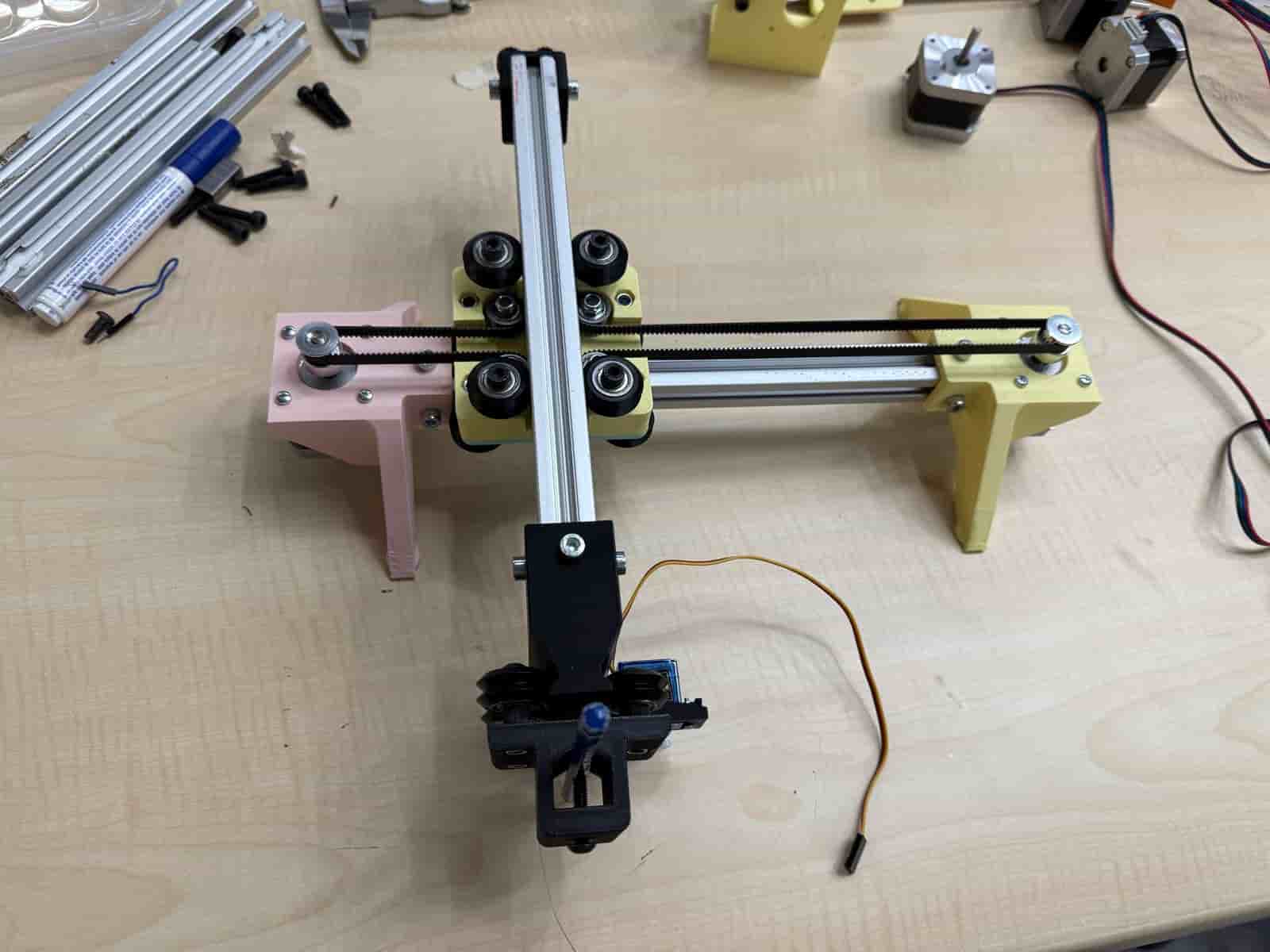
After making sure that the design works, I assembled the feet. For the feet, the following parts are required:
- 2 x Timing Belt Pulley
- 8 x M3x10 Button Cap Screw
- 2 x Motor Leg
- 2 x 42mm x 42mm (face) x 38mm (tall) Stepper Motors
I used 3 T-nuts for each leg to attach the feet.
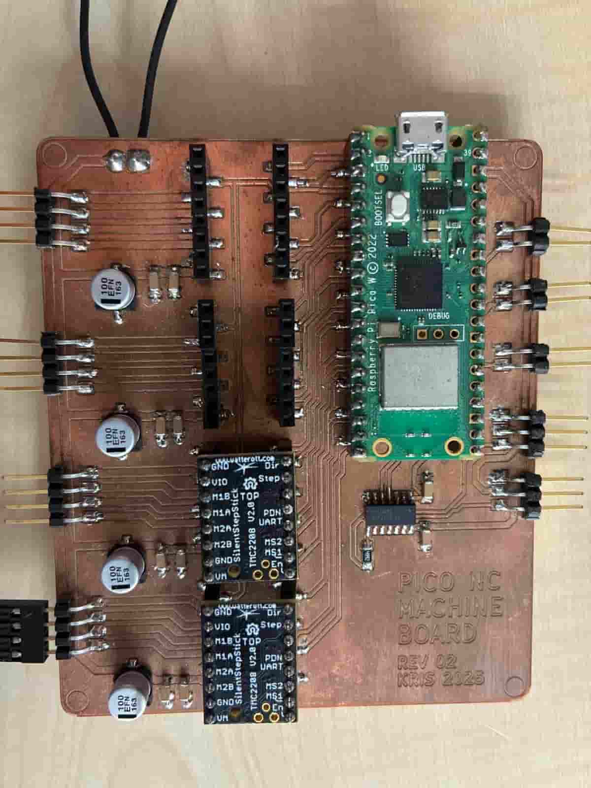
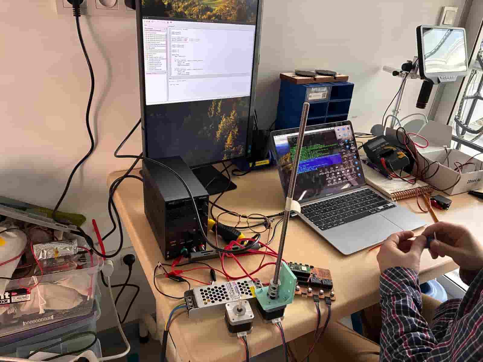
We located the Pico NC board at the lab. This board was designed by Kris for controlling 4 stepper motors and 2 servo motors. We made the power and motor connections.
Then, we tested the stepper and servo motors, which worked successfully but took a little time and dedication to figure out.) We found the pin numbers of each connection.
After adding the two stepper motors in place, I threaded the belt. The first thing I did at this step was to create a loop and attach it through the belt fastener. At the opposite end of the tool holding extrusion. Then, I threaded the belt to pass through the carriage and around the opposite bearing.
Carefully, another loop of the belt is created to pass around the timing belt pulley. The remaining belt is threaded around the second timing belt pulley and back through the belt fastener.
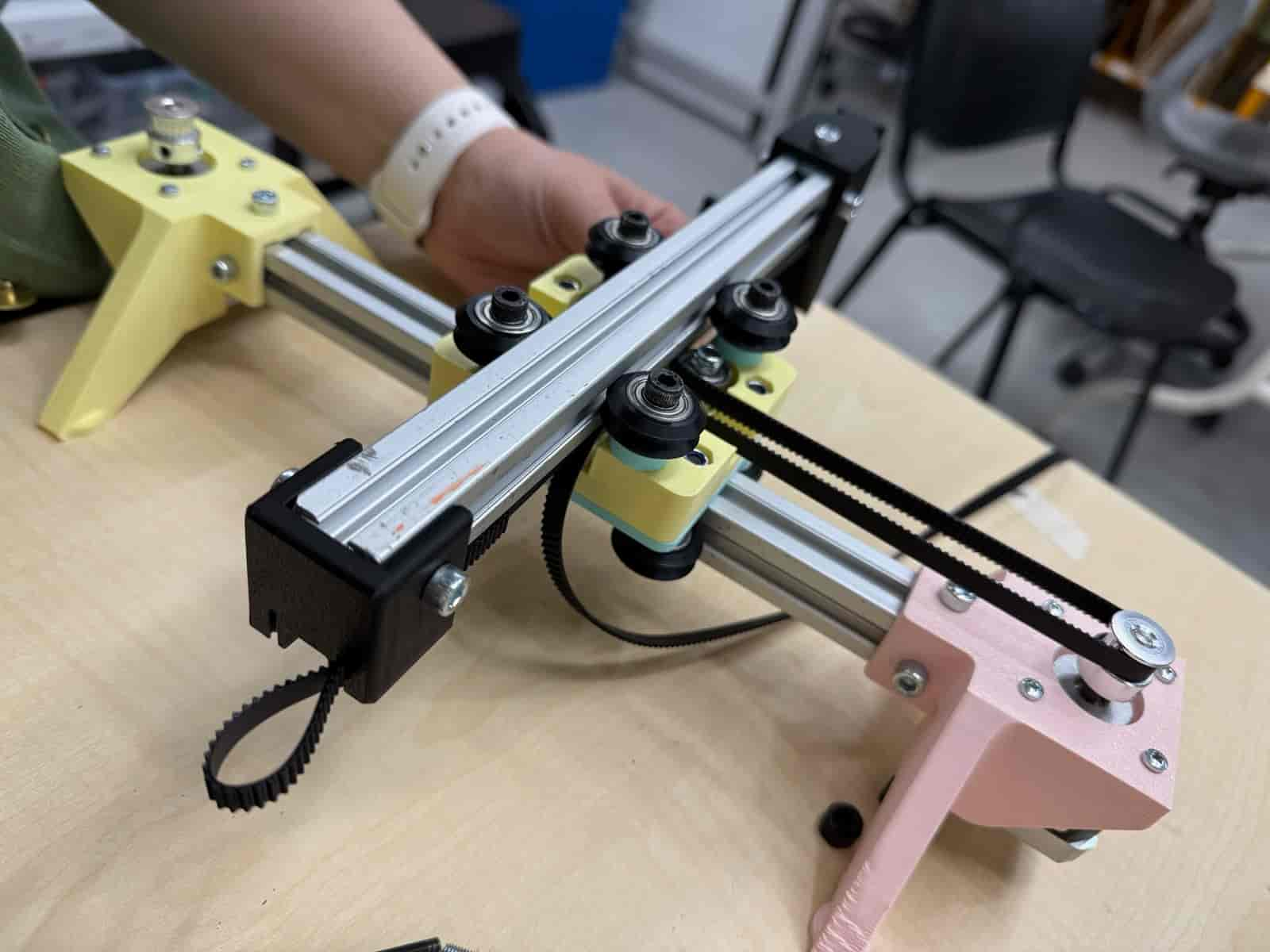
The assembly should look like this when belt threading is completed:
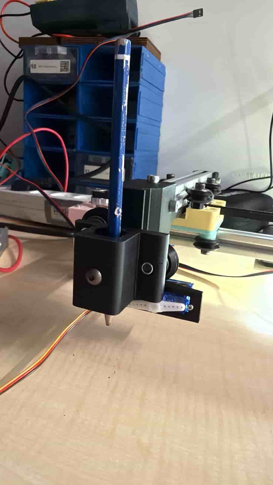
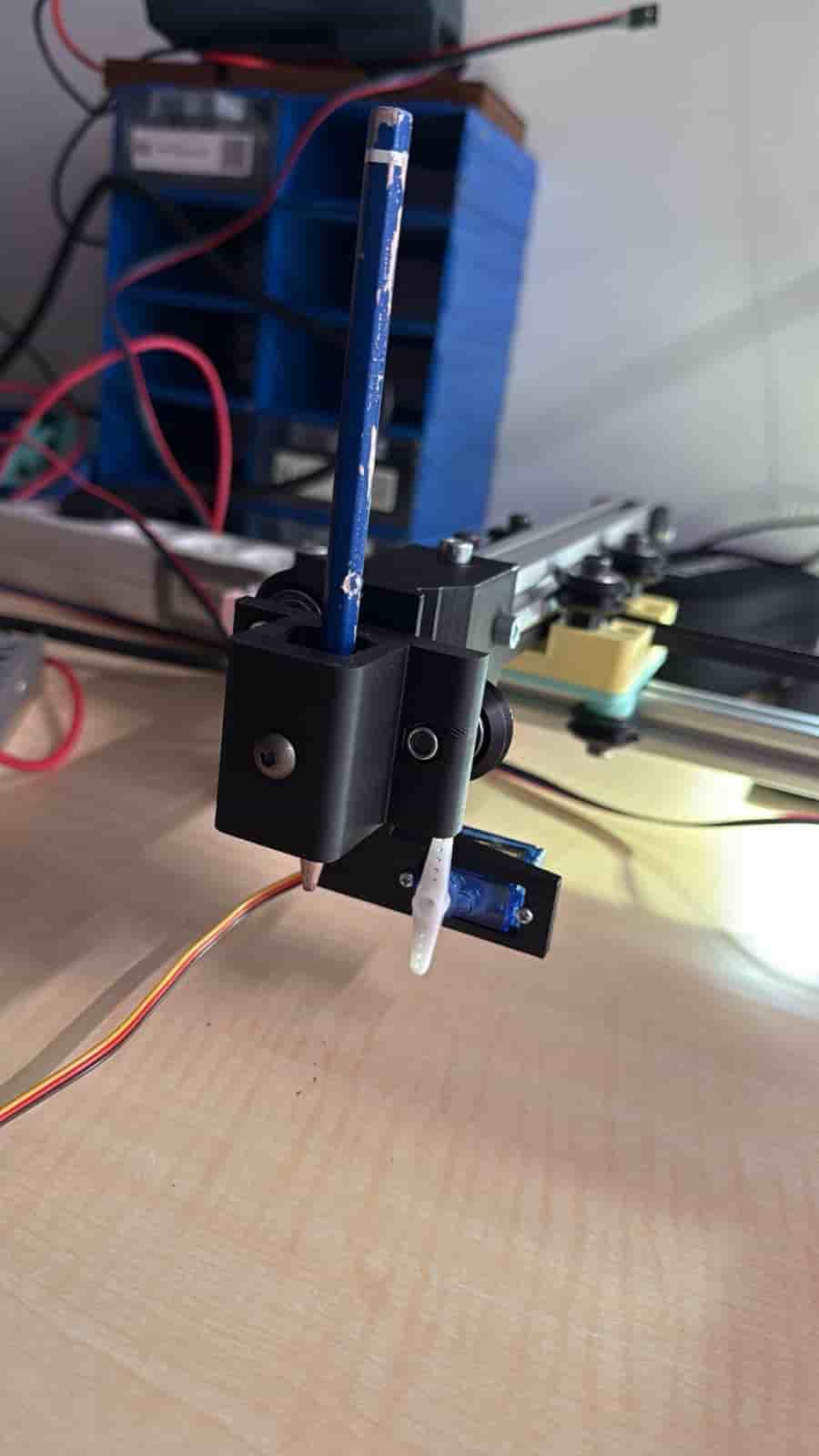
The servo motor on the tool holder acts as a z axis to create the “PEN UP” and “PEN DOWN” motion.
Files: