Touch Me Not
Concept
The starting point was deceptively simple:
What is the most legible way for a chair to say no?
A chair's primary proposition is an invitation to sit. Disrupting that invitation required identifying a mechanism that could make refusal readable—not as malfunction, but as intent.
We explored different mechanisms:
- Swivel
- Rotating the seat away from an approaching user
- Sliding
- Retracting the seat horizontally when approached
- Folding
- Collapsing the seat upward when a human approaches
We aligned with the folding direction because:
- The motion is unambiguous
- The seat withdraws into itself
- It clearly denies the surface of rest
→ It becomes a refusal with a posture
Version 1
Task Allocation
Once the concept was defined, the project was divided to enable parallel work. Tasks were allocated based on: expereince and intrest but there was strong cross-collaboration across all domains. Documentation was a shared responsibility
| Team Member | Responsibilities |
|---|---|
| Auxence | Mechanical + custom component design |
| Dhrishya | V2 software & electrical, video, slides |
| Mohit | Ideation, enclosure, assembly & integration |
| Yara | Initial software & electrical, assembly & integration |
Mechanical Design
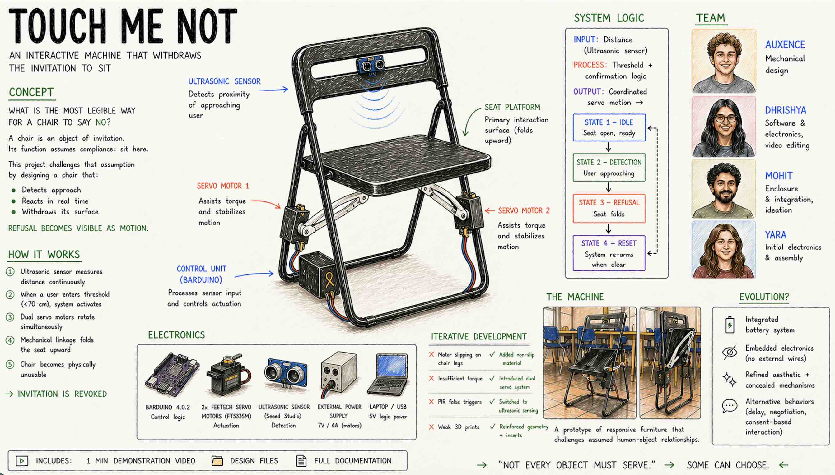
The entire 3D design had to be adapted to the chair, ensuring that every component is securely fixed to it and remains stable when the motors are running. Most of the 3D modeling was done in SolidWorks and Rhino, then 3D printed on the Bambu Lab printers at IAAC. The different parts are assembled using screws and threaded inserts, which keep the structure rigid and prevent any movement when the motors apply force on the seat to fold it.
- Designed to integrate securely with the chair
- Ensures stability under motor actuation
- Easily removabl and no permanent damage or impact to the chair
Tools used: - SolidWorks - Rhino - Bambu Lab 3D printers (IAAC)
Key features: - Screws + threaded inserts for rigidity - Non-slip material added to contact surfaces - Prevents movement during operation - All parts: - Printable without supports - Provided in HTML documentation

Electrical Design
Key Notes
- Ground of Barduino and motor must be connected
- Servo motors include a fourth wire (function still unclear)

Software
Motor Test Code
#include <ESP32Servo.h>

Servo myservo;
int pos = 0;

void setup() {
  myservo.attach(11);
  Serial.begin(9600);
}

void loop() {
  myservo.write(0);
  delay(1000);
  myservo.write(90);
  delay(1000);
}
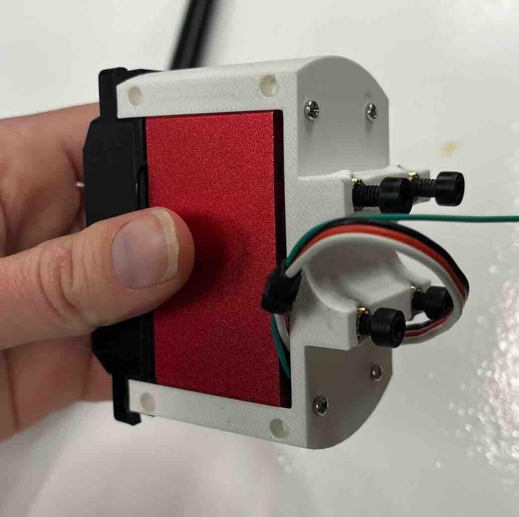
1 Servo + PIR Sensor
#include <ESP32Servo.h>

Servo servo1;
int servoPin1 = 11;
int pirPin = 15;
int pirState = 0;

void setup() {
  Serial.begin(9600);
  servo1.attach(servoPin1);
  servo1.write(0);
  pinMode(pirPin, INPUT);
}

void loop() {
  pirState = digitalRead(pirPin);

  if (pirState == HIGH) {
    Serial.println("Motion detected!");
    servo1.write(90);
    delay(2000);
  } else {
    servo1.write(0);
  }

  delay(2000);
}
Iterative Problem Solving
Issues & Solutions
- Poor grip on chair legs
- Motor housing rotated instead of lifting seat
- ✅ Solution: added rubber tape for friction
- Insufficient motor torque
- Single motor could not lift seat
-
✅ Solution: added second servo
-
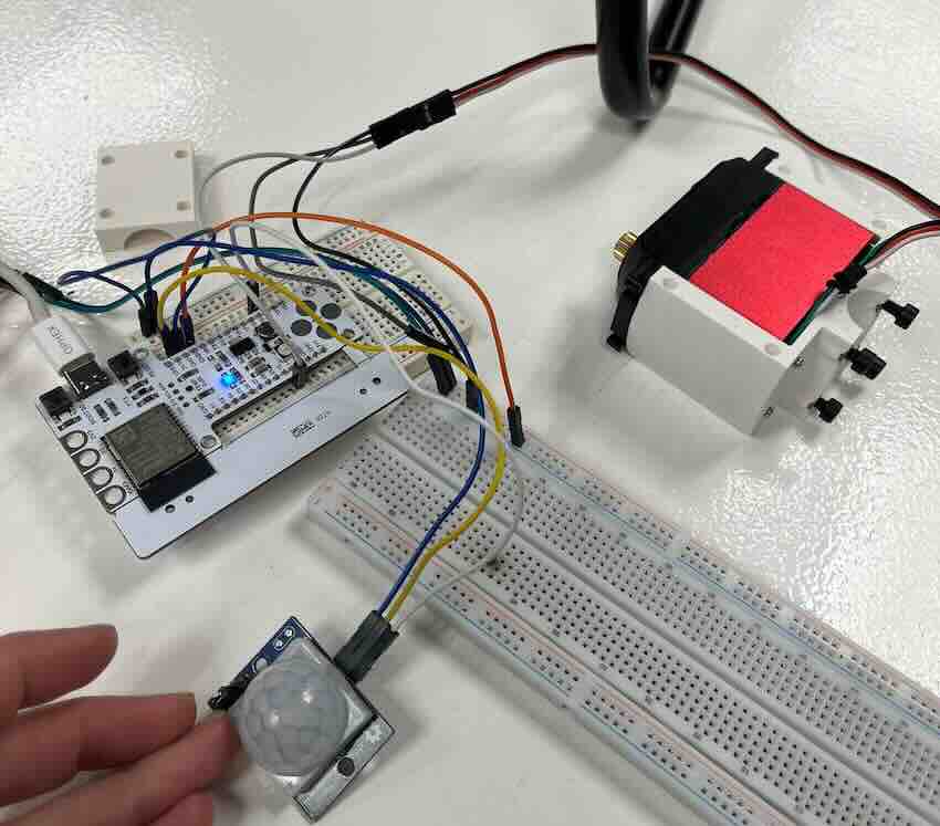
3D print structural weakness
- Holes too small, walls too thin
- Plastic bulged under screw pressure
- ✅ Solution: redesigned components
- Unreliable PIR sensor
- Triggered randomly
- Required shielding
- ✅ Solution: switched to ultrasonic sensor
Final Version
Machine Components
| Component | Purpose | Spec | Link |
|---|---|---|---|
| Barduino 4.0.2 | Control + logic | CERN OHL V1.2 | https://fablabbcn-projects.gitlab.io/electronics/barduino-docs/ |
| FeeTech Servo | Motion | FT5335M | https://www.pololu.com/file/0J1434/FT5335M-specs.pdf |
| Proximity Sensor | Human detection | Seeed 101020010 | Link |
| Computer | 5V power | Mac | NA |
| DC Power Supply | 7V servo power | LABPW3005N | NA |
| Custom Components | Structure + motion | — | See files |
Software (Final Version)
2 Servos + Ultrasonic Sensor
// (code unchanged — included fully)
#include <ESP32Servo.h>

const int US_PIN      = 4;
const int SERVO1_PIN  = 18;
const int SERVO2_PIN  = 17;
const long TRIGGER_DIST_CM = 70;
const int  CONFIRM_READS   = 3;

Servo servo1;
Servo servo2;

bool triggered  = false;
int  closeCount = 0;

void moveSync(int target1, int target2, int stepDelay = 12) {
  int cur1 = servo1.read();
  int cur2 = servo2.read();
  int steps = max(abs(target1 - cur1), abs(target2 - cur2));

  if (steps == 0) return;

  for (int i = 1; i <= steps; i++) {
    servo1.write(cur1 + (target1 - cur1) * i / steps);
    servo2.write(cur2 + (target2 - cur2) * i / steps);
    delay(stepDelay);
  }
}

long readDistanceCm() {
  pinMode(US_PIN, OUTPUT);
  digitalWrite(US_PIN, LOW);
  delayMicroseconds(2);
  digitalWrite(US_PIN, HIGH);
  delayMicroseconds(10);
  digitalWrite(US_PIN, LOW);

  pinMode(US_PIN, INPUT);
  long duration = pulseIn(US_PIN, HIGH, 30000);

  if (duration == 0) return -1;
  return duration * 0.034 / 2;
}

void setup() {
  Serial.begin(115200);

  servo1.attach(SERVO1_PIN, 500, 2500);
  servo2.attach(SERVO2_PIN, 500, 2500);

  servo1.write(90);
  servo2.write(90);

  delay(1000);
}

void loop() {
  long dist = readDistanceCm();

  bool isClose = (dist > 0 && dist < TRIGGER_DIST_CM);

  if (isClose) closeCount++;
  else closeCount = 0;

  if (closeCount >= CONFIRM_READS && !triggered) {
    triggered = true;
    moveSync(180, 0);
    moveSync(60, 120);
  }

  if (!isClose && triggered) {
    triggered = false;
  }

  delay(100);
}
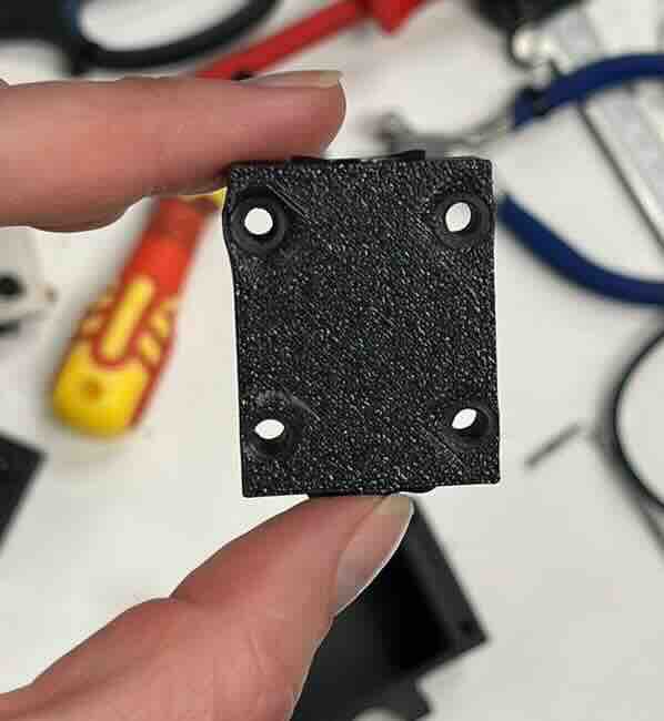
Final Mechanical Design
For the final version, we updated the 3D files of the motor supports to make them more solid and to ensure the inserts fit better and stay stable. In the previous iteration, the holes were too small and the surrounding walls too thin, which caused the prints to crack and the inserts to come loose when tightening the parts onto the chair. We also added an enclosure to house the Arduino and the wiring, hiding them from view and giving the machine a more finished look rather than a prototype appearance.
One remaining limitation is the power supply: the Arduino still needs to be powered at 5V through a laptop connection, and the motors require 7V and 4A from an external power supply. As a result, the machine doesn't yet appear fully self-contained, we simply don't have suitable batteries for this setup at the moment.
- Reinforced motor supports
- Improved insert fit and wall thickness
- Prevented cracking during tightening
- Added enclosure:
- Hides wiring
- Improves visual finish
Limitation
- Not fully self-contained:
- Arduino requires USB power
- Motors require external 7V / 4A supply
Future Improvements
- Solder connections
-
For a more permanent machine we would solder the electrical components rather than using a breadboard - for this design we chose not to solder because we wanted to be able to fully repurpose the Barduino and other components. Since we had an enclosure for the board and associated wires, the design served its purpose in the current form.
-
Portable power
-
The servo we chose required an odd 7V power sources. We chose to keep this aspect of the project simple by using our labs DC Power Supply. For a more permanent installation we would need to specify and integrate a battery or converter coupled with an alternative supply.
-
Aesthetics
- The servo we chose required an odd 7V power sources. We chose to keep this aspect of the project simple by using our labs DC Power Supply. For a more permanent installation we would need to specify and integrate a battery or converter coupled with an alternative supply.