Week10 - Output Devices
Power Consumption Testing – Stepper & Servo Motors
Overview
This experiment focused on measuring the voltage, current, and power consumption of 2 motors using a regulated power supply and a multimeter. - stepper motor - micro servo motor 9g (SG90)
The goal was to understand:
- how much power each motor consumes
- how consumption changes during operation
- differences between idle and active states
what we used
- stepper motor + driver
- servo motor
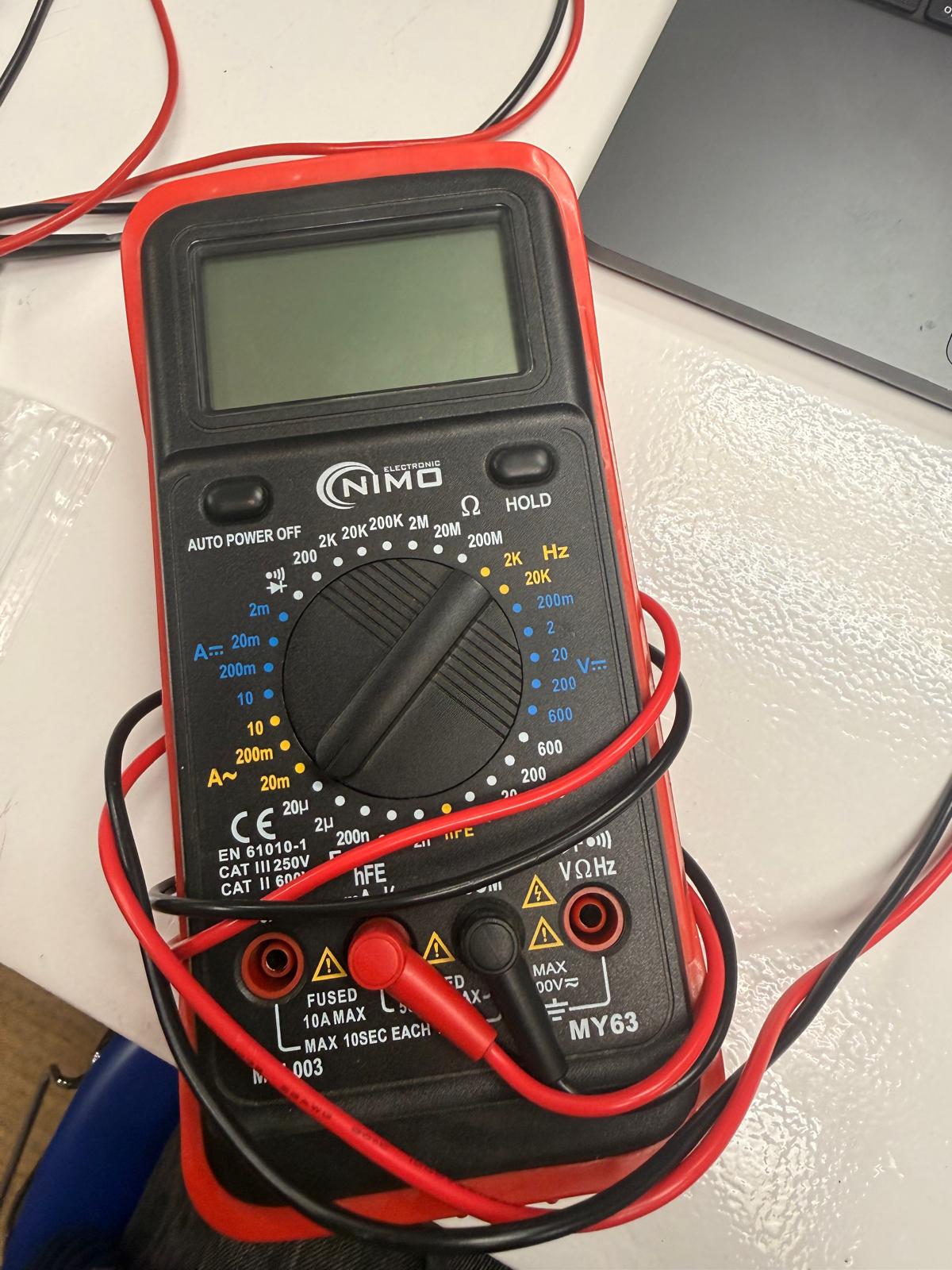
- multimeter
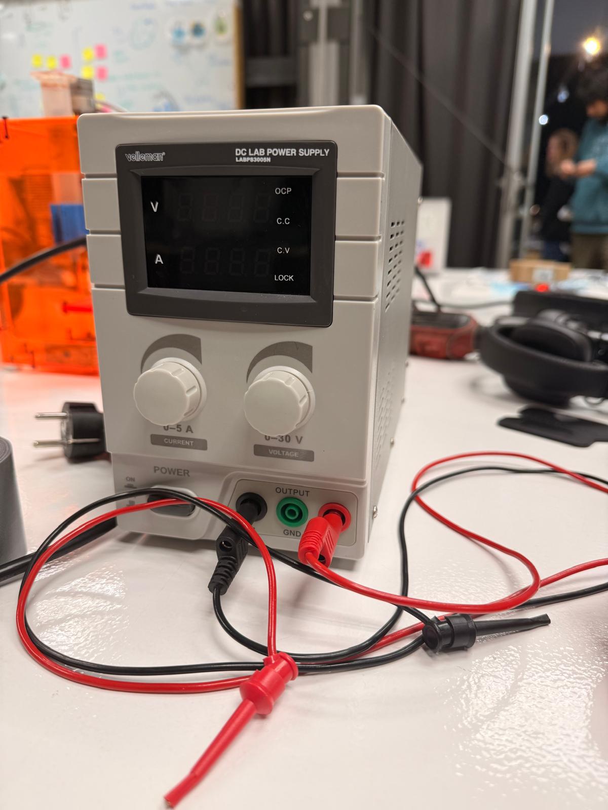
- DC Voltage power supply
- arduino
- jumper cables
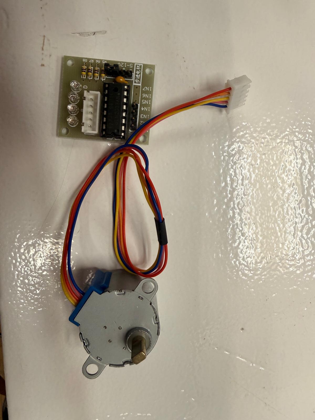
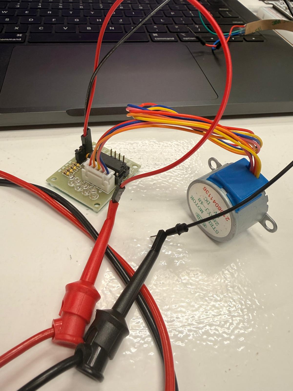
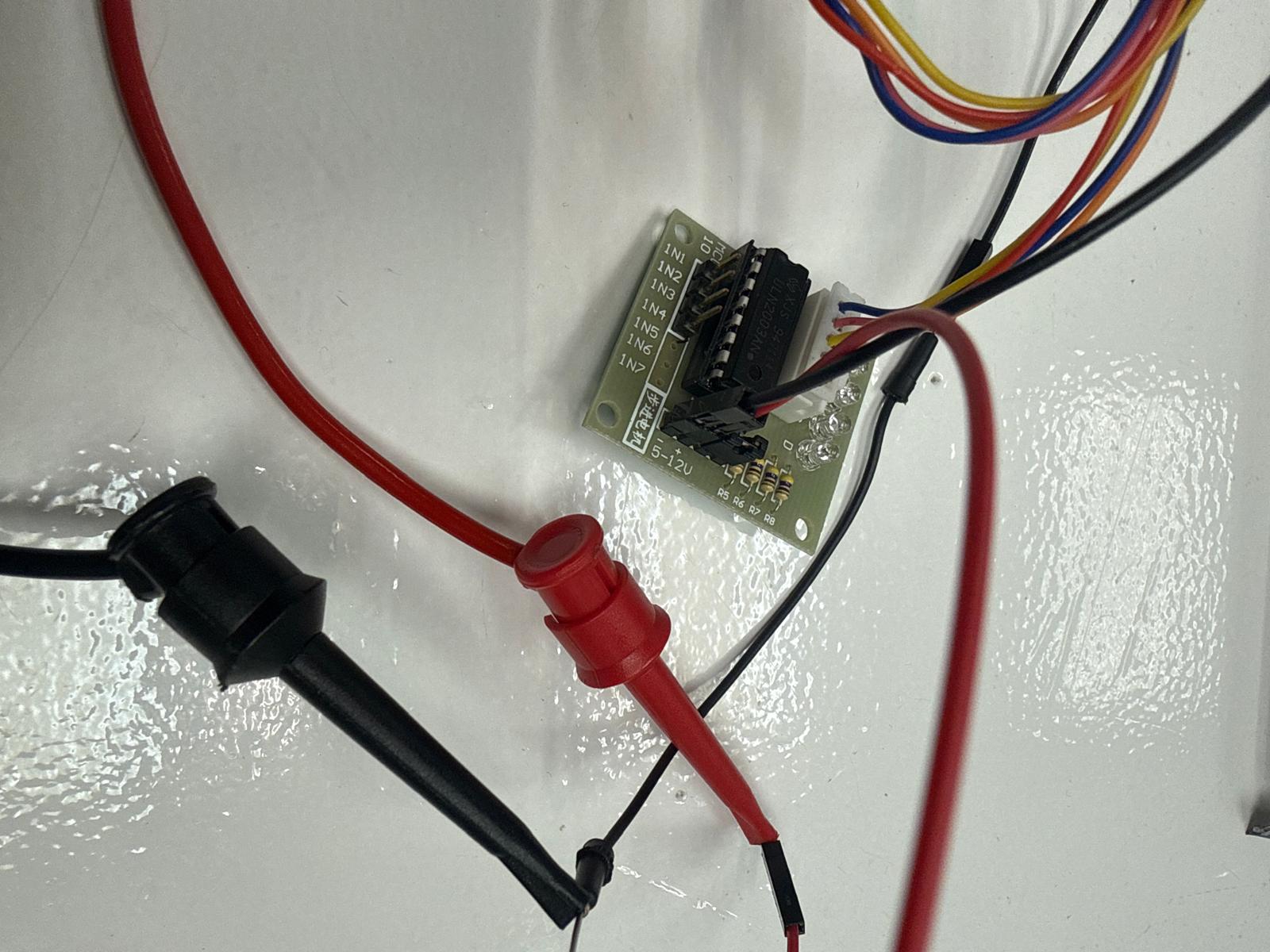
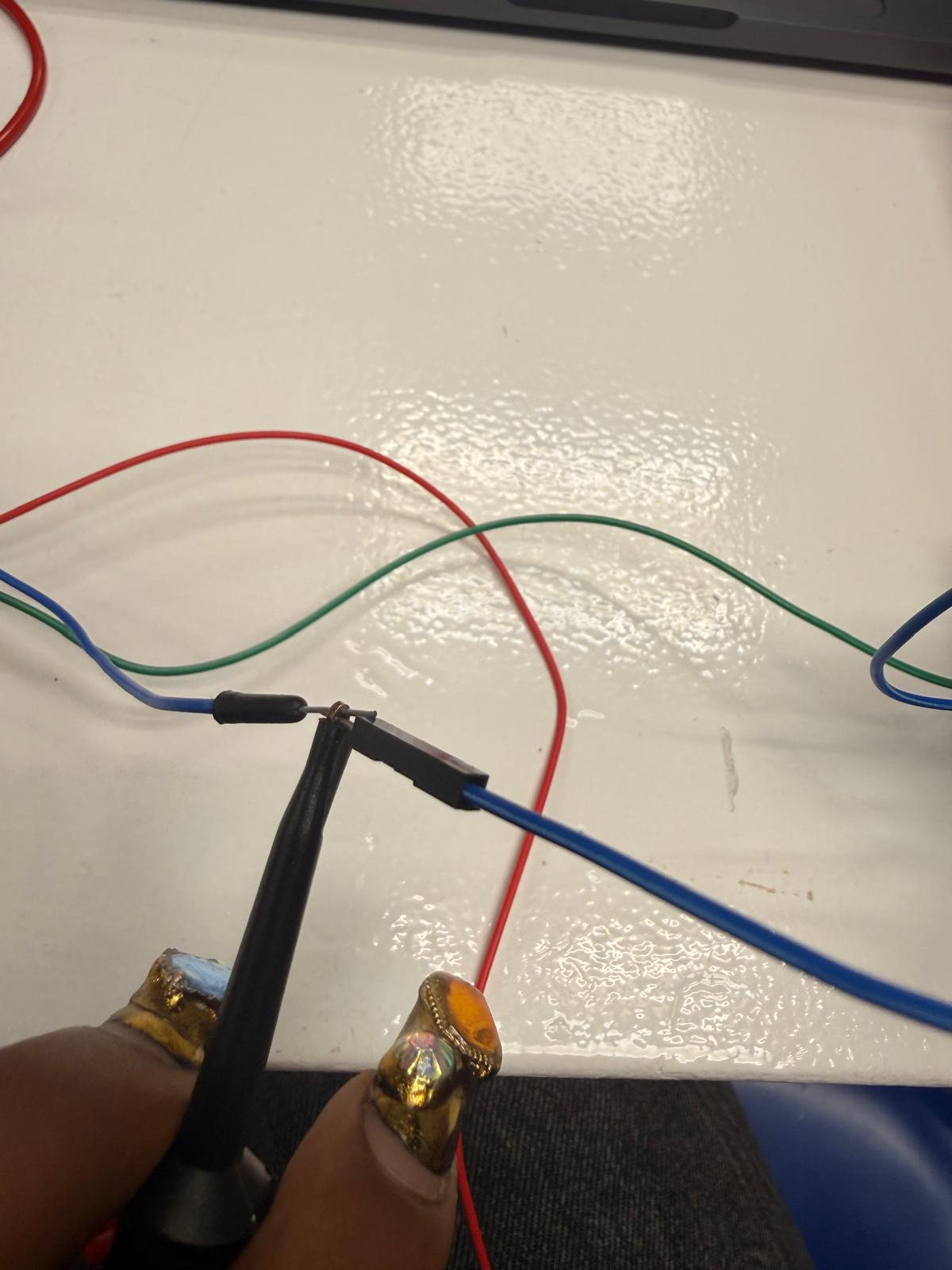
1. Stepper motor
connections
driver VCC -> Power Source Unit RED driver GND -> Power Source Unit BLACK
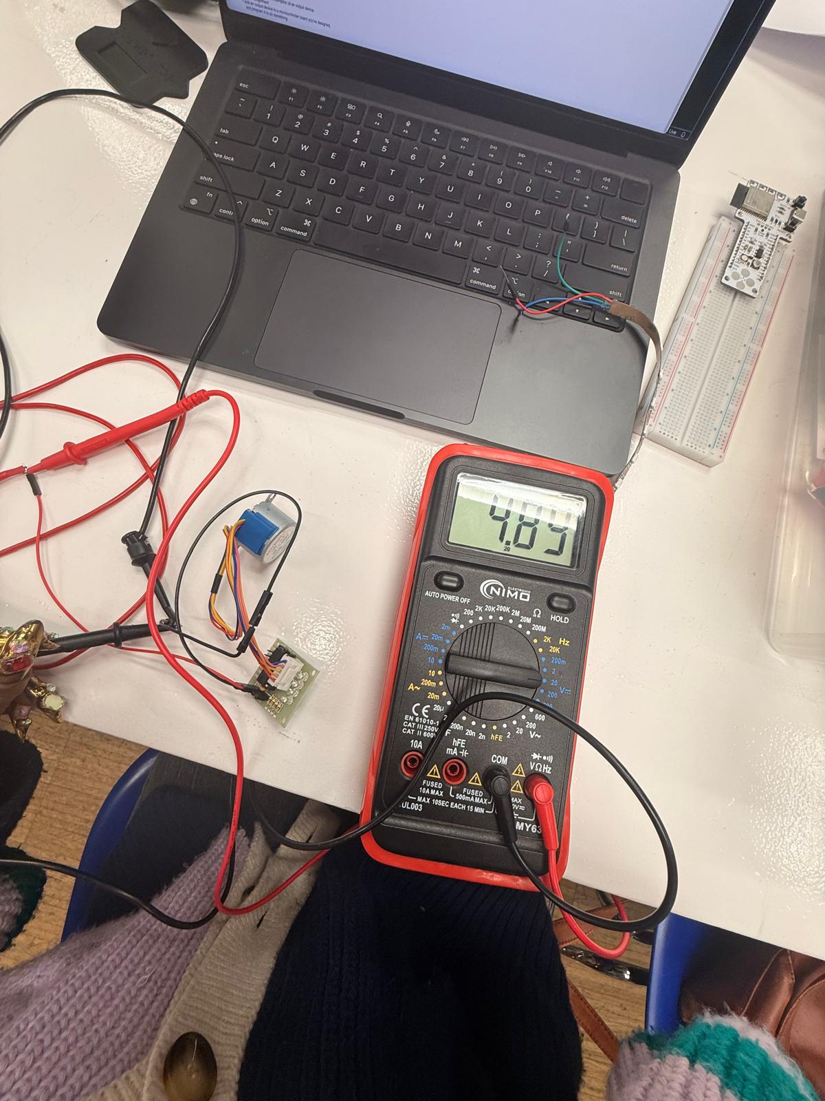
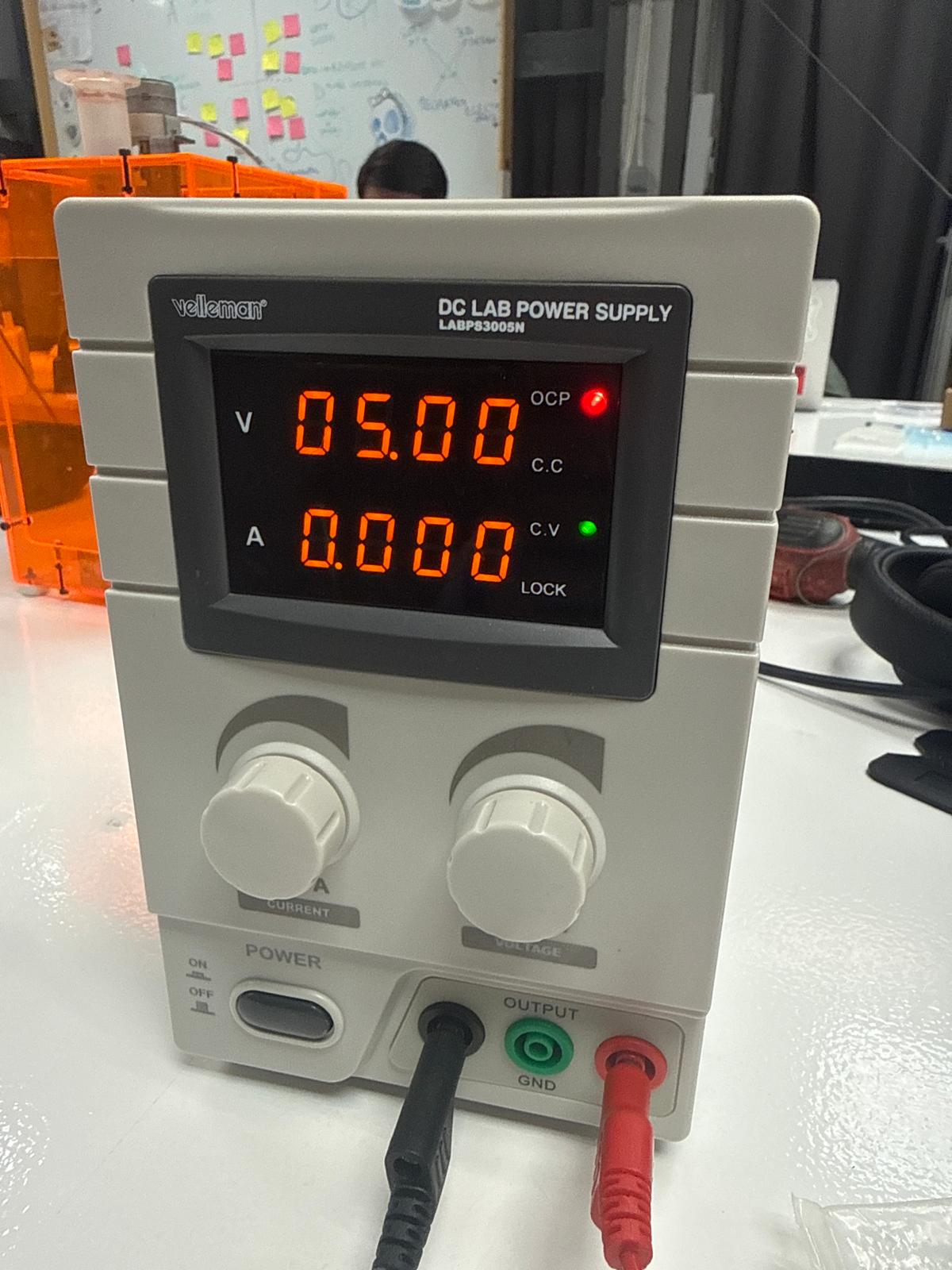
Setup
- Power supply set to 5V
- Multimeter used in DC voltage mode
- Probes placed across VCC and GND
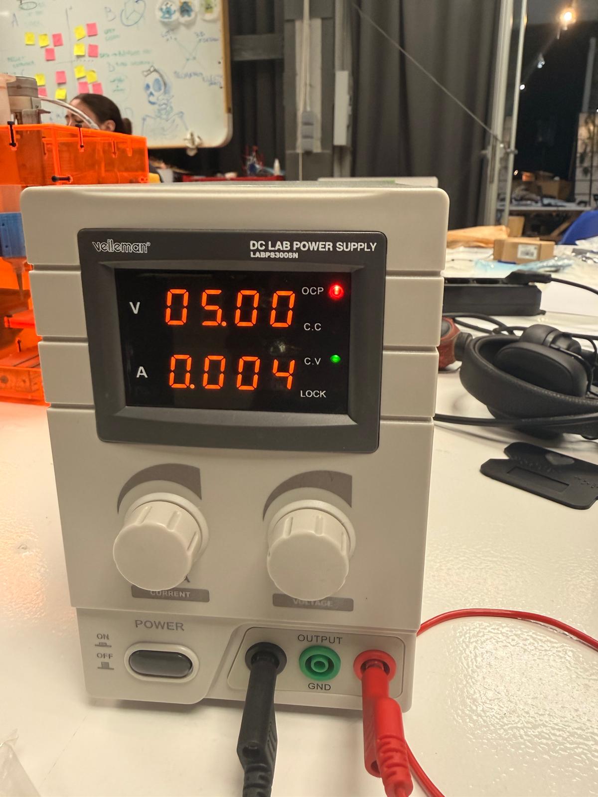
Observations
- Measured voltage: 4.99 V
- Current observed: ~0.1 A
Power Consumption Calculations
Power is calculated using:
P = V × I
Power
P = 5 × 0.1 = 0.5 W
notes
Stepper motors consume almost the same power in idle and spinning states
Images
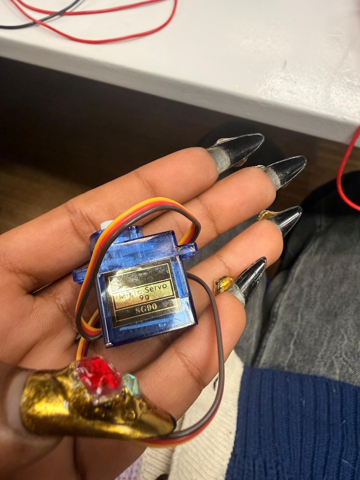
2. Servo Motor Power Test
A micro servo motor was tested using an external power supply and controlled via a barduino connected to Arduino IDE
Setup
- Voltage supply: 5V
- Servo powered directly from PSU
- Signal controlled via Barduino
- Shared ground between PSU and microcontroller
connections
PSU RED -> Servo Red PSU GND -> Servo Brown PSU GND -> Arduino GND Servo Yellow -> Arduino Pin 9
test code
this made the motor stop and turn every few seconds to measure all states I had to download the ESP32Servo library
include
Servo myServo;
const int servoPin = 9; // change if needed
void setup() { myServo.setPeriodHertz(50); // standard servo frequency myServo.attach(servoPin, 500, 2400); }
void loop() { myServo.write(0); delay(1500);
myServo.write(90); delay(1500);
myServo.write(180); delay(1500);
myServo.write(90); delay(1500); }
Images
3. Current Measurements
Idle State (Not Moving)
- Current: 0.05 A
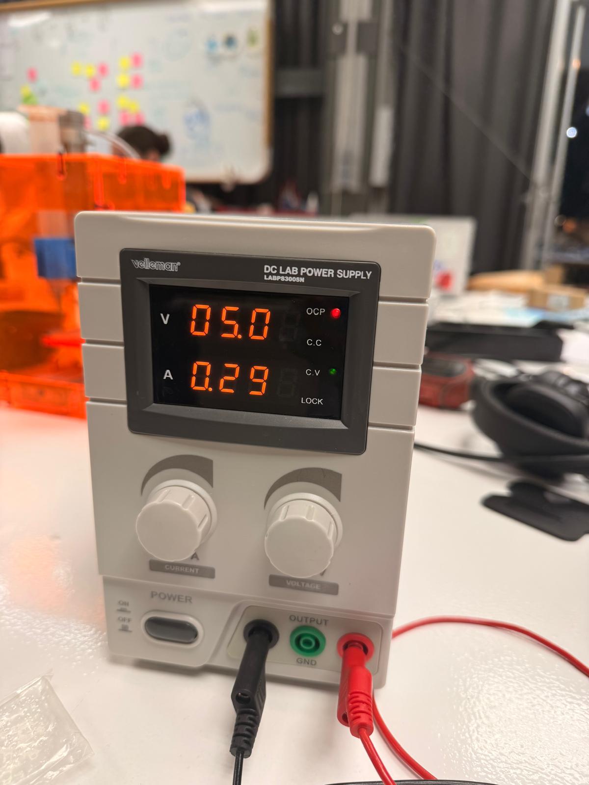
Active State (Moving)
- Current ranges up to: 0.345 A
Observations
- Current increases significantly when the motor is in motion
- The servo consumes minimal power when idle
- Rapid fluctuations occur during movement
4. Power Consumption Calculations
Power is calculated using:
P = V × I
Idle Power
P = 5 × 0.05 = 0.25 W
Active Power (Maximum Observed)
P = 5 × 0.345 = 1.725 W
Summary Table
| State | Voltage (V) | Current (A) | Power (W) |
|---|---|---|---|
| Idle | 5.0 | 0.05 | 0.25 |
| Moving (max) | 5.0 | 0.345 | 1.725 |
5. Key Observations
- Servo motors draw very little current when idle
- Power consumption increases during motion
- Current fluctuates dynamically while moving
- Peak current depends on:
- speed of movement
- load on the motor
6. Important Notes
- Power consumption can increase with load on the motor
- Sudden movements cause current spikes
- A stable external power supply improves measurement accuracy
- USB power alone can result in unreliable readings
7. Comparison Insight (Stepper vs Servo)
| Motor Type | Idle Consumption | Behavior |
|---|---|---|
| Stepper Motor | High | Consumes power even when holding |
| Servo Motor | Low | Consumes more only when moving |
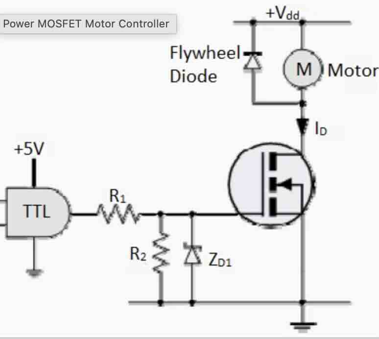
9. Video Documentation
Simple circuit with a small motor and a mosfet.
One important element of the output circuit is a flywheel diode that runs parallel to the motor. The purpose of this element is to discharge energy when the ciricuit is switched off.
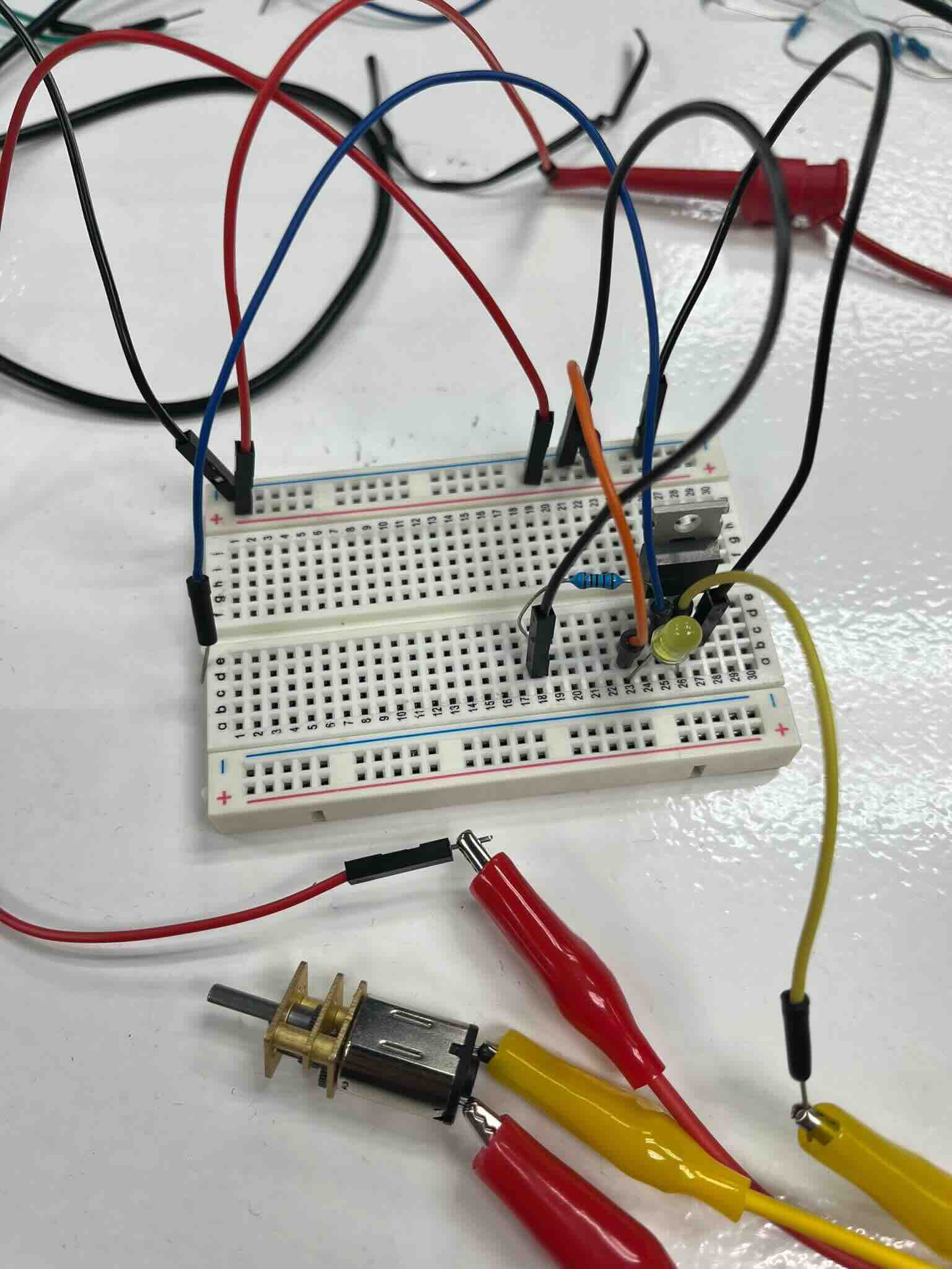
We had this small motor on hand
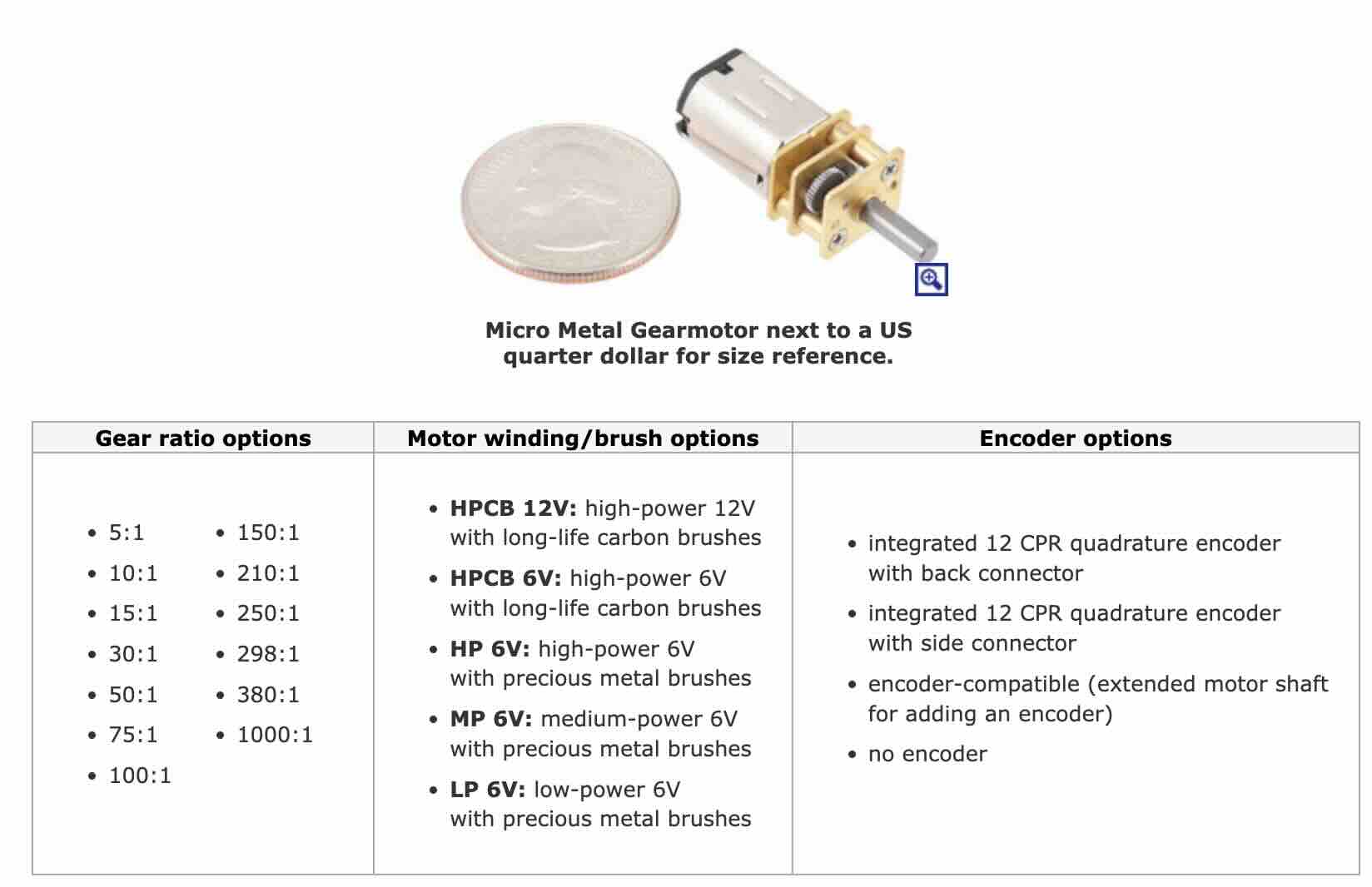
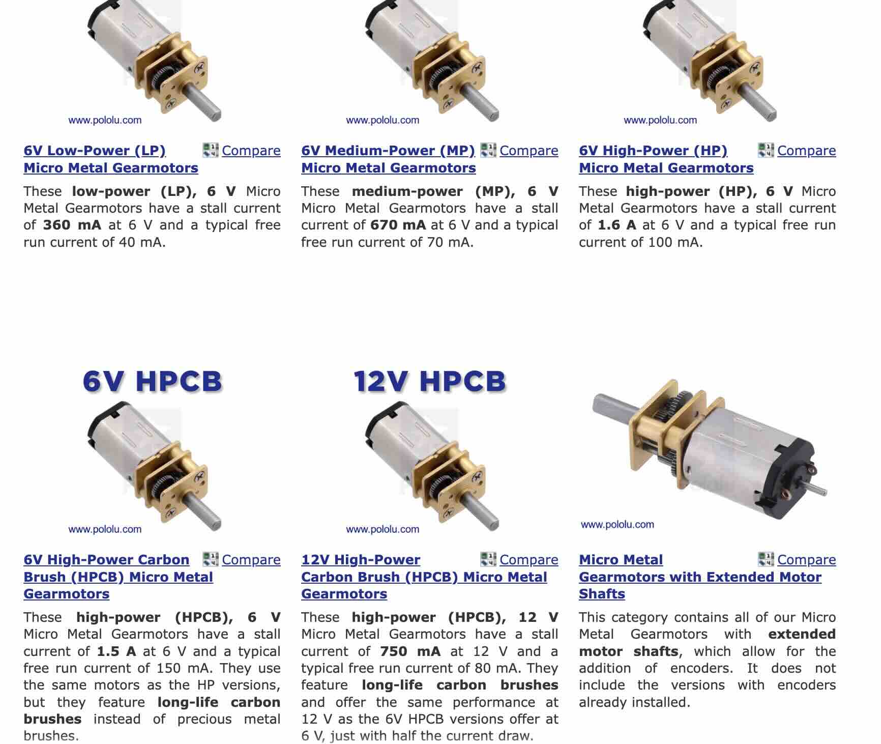
Although we knew the general specification of the motor we did not know the exact part number. We used our ciriut and power readings to determine which of these options we had.
This video shows the circuit with the mosfet and flywheel diode. We used an LED diode so that we could visualize the backflow. Normally a LED diode is not appropriate for th is application because it will likely burn out.
Power Measurements Results
| Input Voltage | Current | Power |
|---|---|---|
| 2 | 0 | none |
| 5 | 0.031 | 0.155 |
| 6 | 0.032 | 0.224 |
Based on these results we were able to determine that our motor most closely matches the specifications for the 6V Low Voltage motor.