Week 03 - Computer-Controlled Cutting
We got an introduction to Fusion from Dani and designed this piece to test tolerance and fit between the joints.
We then got a tour of the laser cutters at Fab Lab Barcelona.
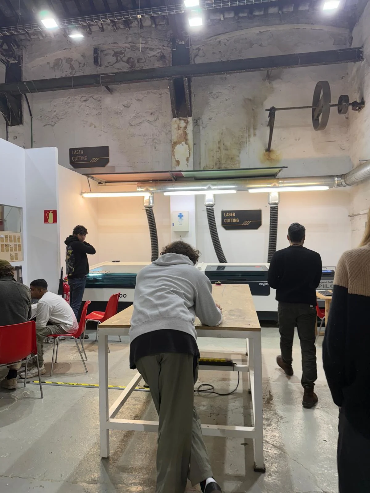
We have the following laser cutters in the lab:
- Rayjet 500 (the one we tested with)
- 60W CO2 laser cutter
- Bed size: 500 × 300 mm
-
Max material thickness: ~10 mm
-
Rayjet 400
- 40W CO2 laser cutter
- Bed size: 400 × 300 mm
-
Max material thickness: ~8 mm
-
Epilog Legend 36EXT
- 60W CO2 laser cutter
- Bed size: 914 × 610 mm
-
Max material thickness: ~10 mm
-
Trotec Speedy 100
- 30W CO2 laser cutter
- Bed size: 610 × 305 mm
- Max material thickness: ~6 mm
Note: Material thickness values are approximate since they depend on the material type, focus distance, machine setup, and power/speed settings.
We then did a small test on the Rayjet 500 to understand how the machine worked.
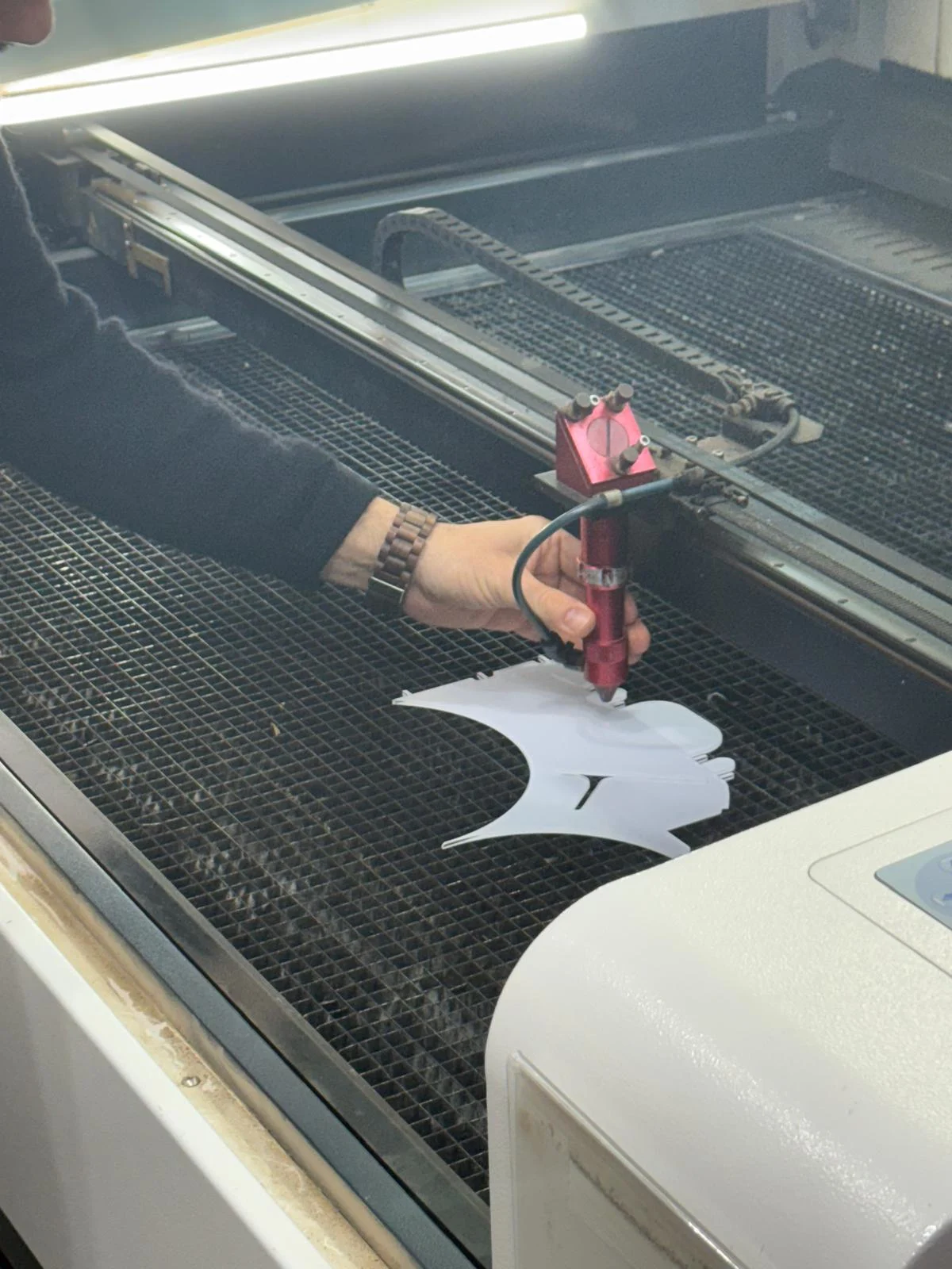
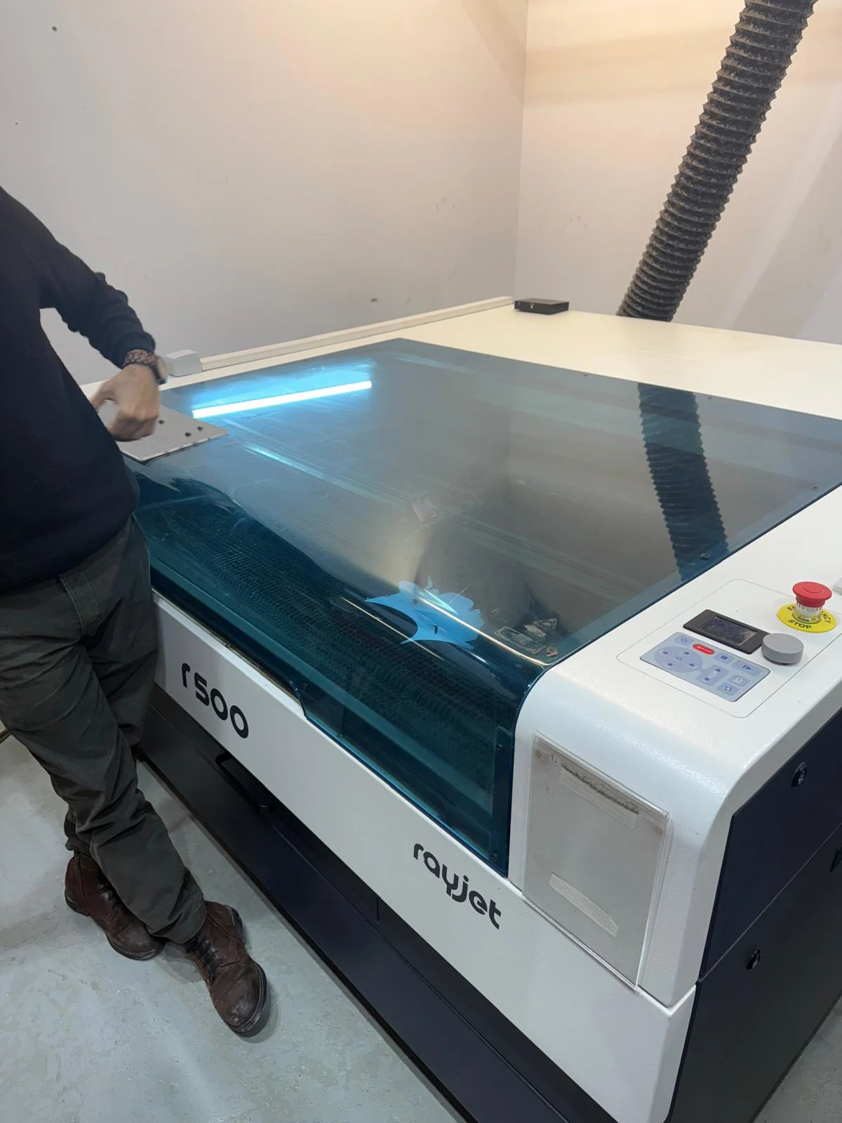
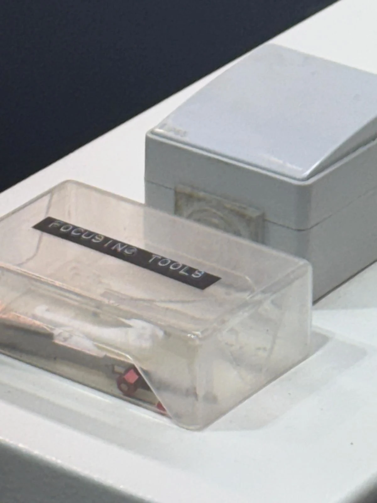
Each machine has its own focus tool. We focused the machine by keeping the laser height at 0.
Safety and Process Considerations
- Always close the top lid of the machine before starting the cut.
- Ensure proper ventilation in the workspace to avoid inhaling fumes from cutting materials. Turn on the valves, switches, ventilator, and exhaust fan while working with the machine.
- Use appropriate materials for laser cutting. Avoid cutting materials that can release toxic fumes, such as PVC or certain types of foam.
- Always perform the inside cuts first to prevent the material from shifting during the cutting process.
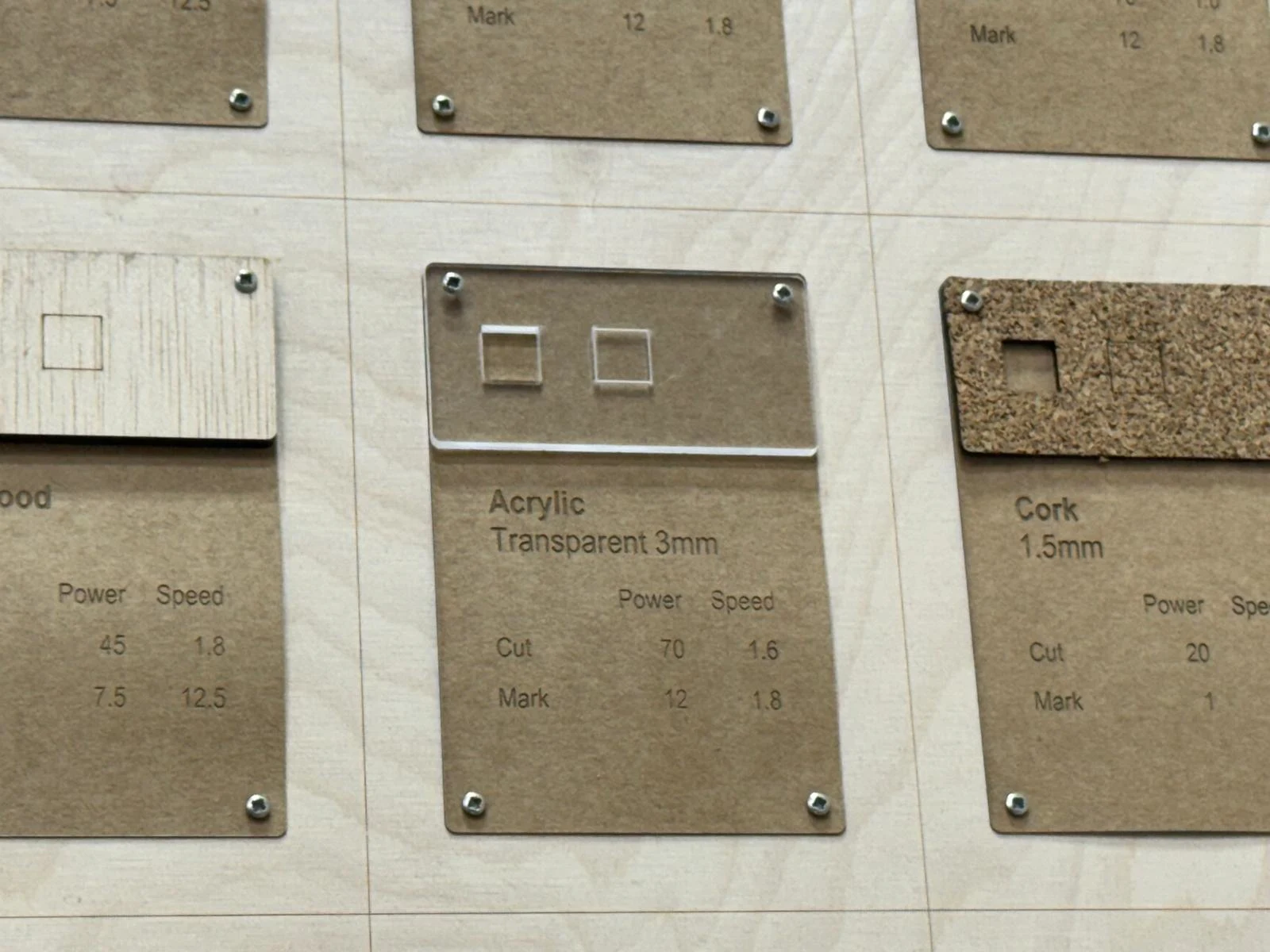
- Always do a test cut before starting the final cut to ensure the settings are correct. There are test swatches available in the lab, and it is useful to test both material settings and design tolerances.
- Be cautious when cutting reflective materials since the laser system uses mirrors to direct the beam. Reflective surfaces can redirect the laser unexpectedly and potentially cause damage or injury. It is recommended to cover one side with temporary masking material to absorb excess laser energy.
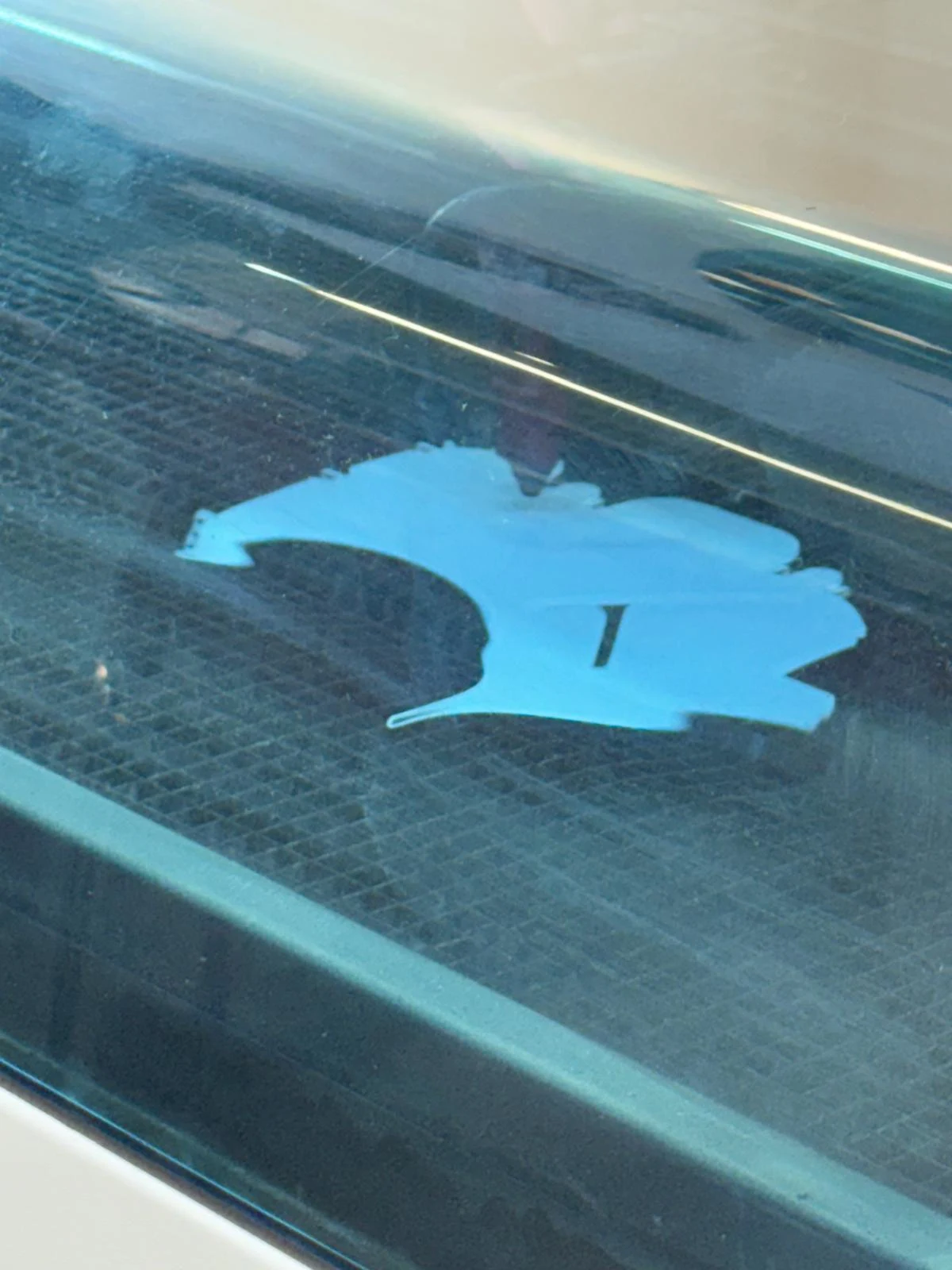
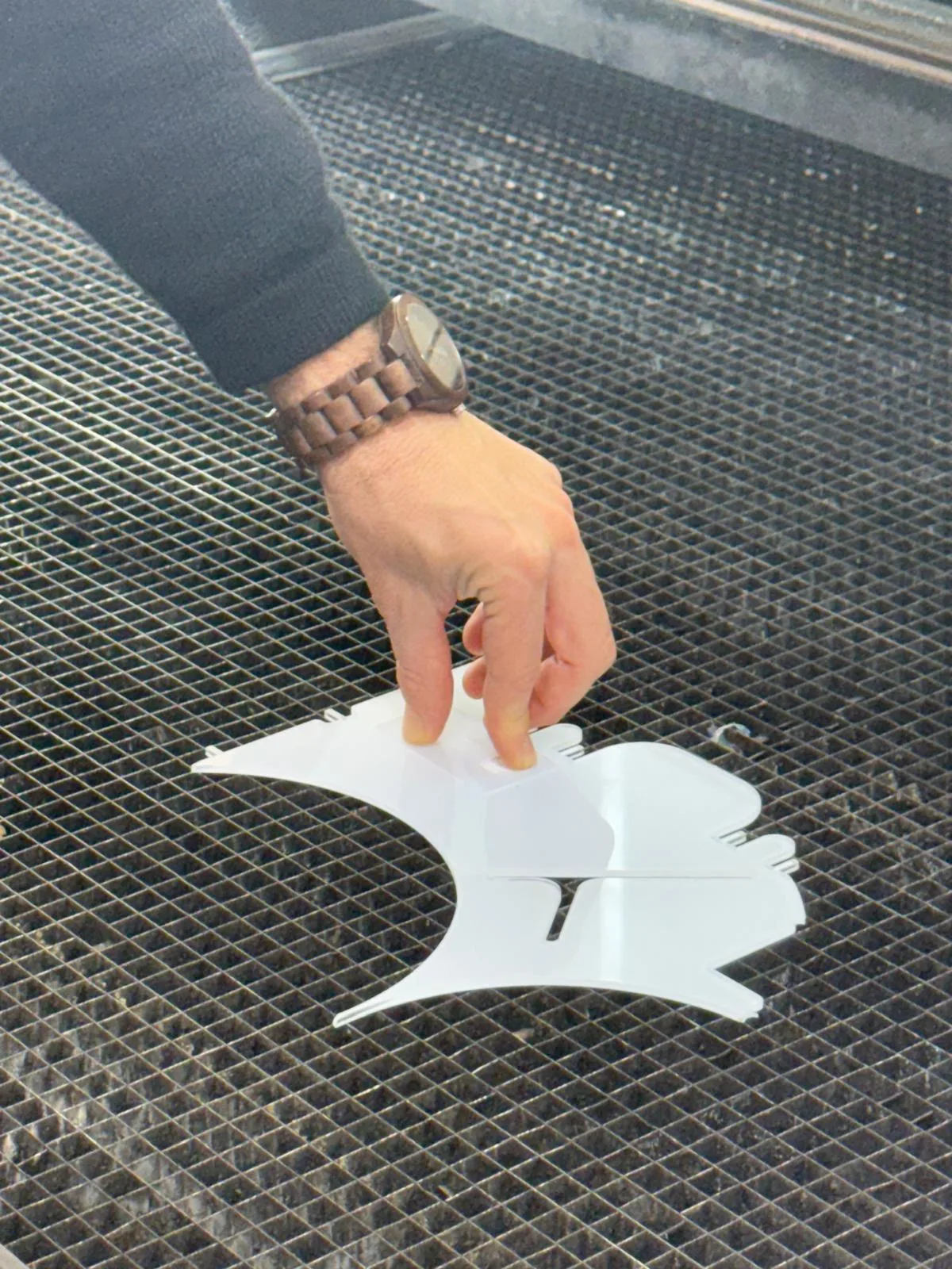
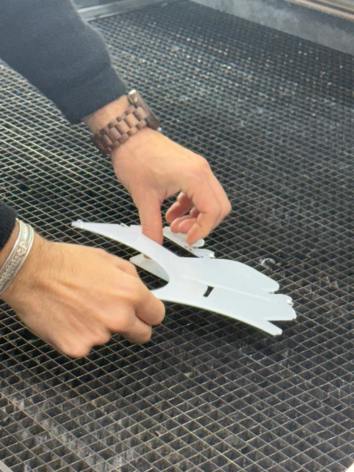
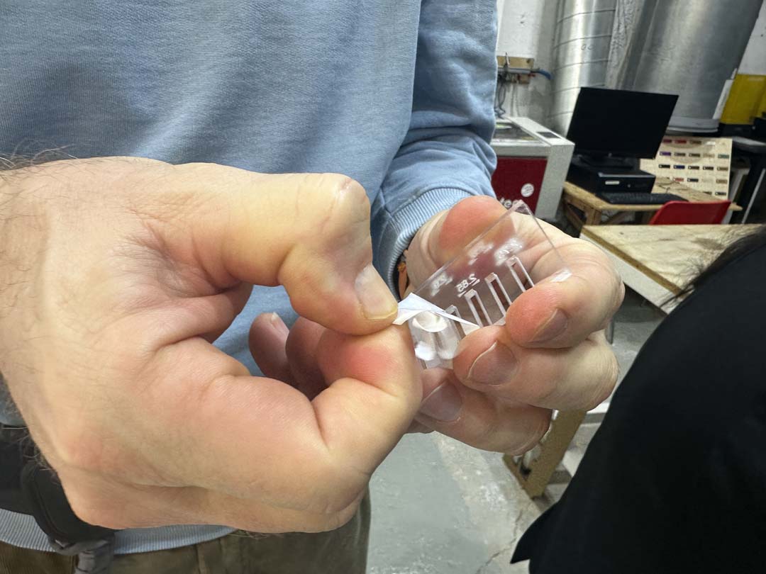
We cut the parts in acrylic to test the tolerance fit that Dani showed us how to design in Fusion.
We used the settings from the test swatch. I used the lab computer connected to the machine to start the cut.
We also took the test required to join the booking system and learned how to use it.
Laser Cutter Kerf Characterization
What is Kerf?
The laser beam has a physical width, so it vaporizes a thin strip of material along every cut. That strip is called the kerf. It means slots come out slightly wider than designed and tabs come out slightly narrower. This matters for press-fit parts in particular, so we need to know the kerf value and compensate for it in our designs.
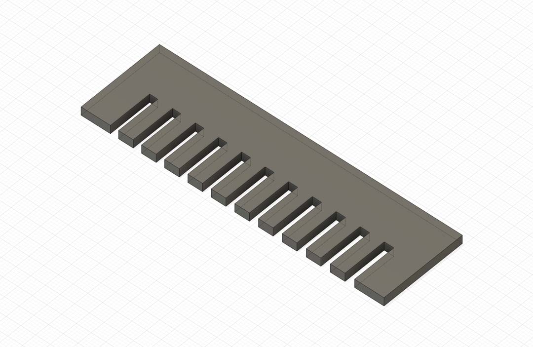
Designing the Comb
A kerf comb is a quick way to measure kerf. It's a flat piece with a row of slots, each varying slightly in width. You can slide a scrap of the same material into the slots until you find the one that fits, and that tells you the effective cut width.
We designed ours parametrically in Fusion 360. All the key dimensions are driven by user parameters, so it's easy to regenerate the comb for a different material or step size.
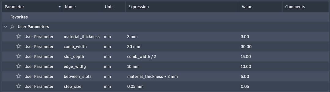
| Parameter | Expression | Value |
|---|---|---|
material_thickness |
3 mm | 3.00 mm |
comb_width |
30 mm | 30.00 mm |
slot_depth |
comb_width / 2 |
15.00 mm |
edge_width |
10 mm | 10.00 mm |
between_slots |
material_thickness + 2 mm |
5.00 mm |
step_size |
0.05 mm | 0.05 mm |
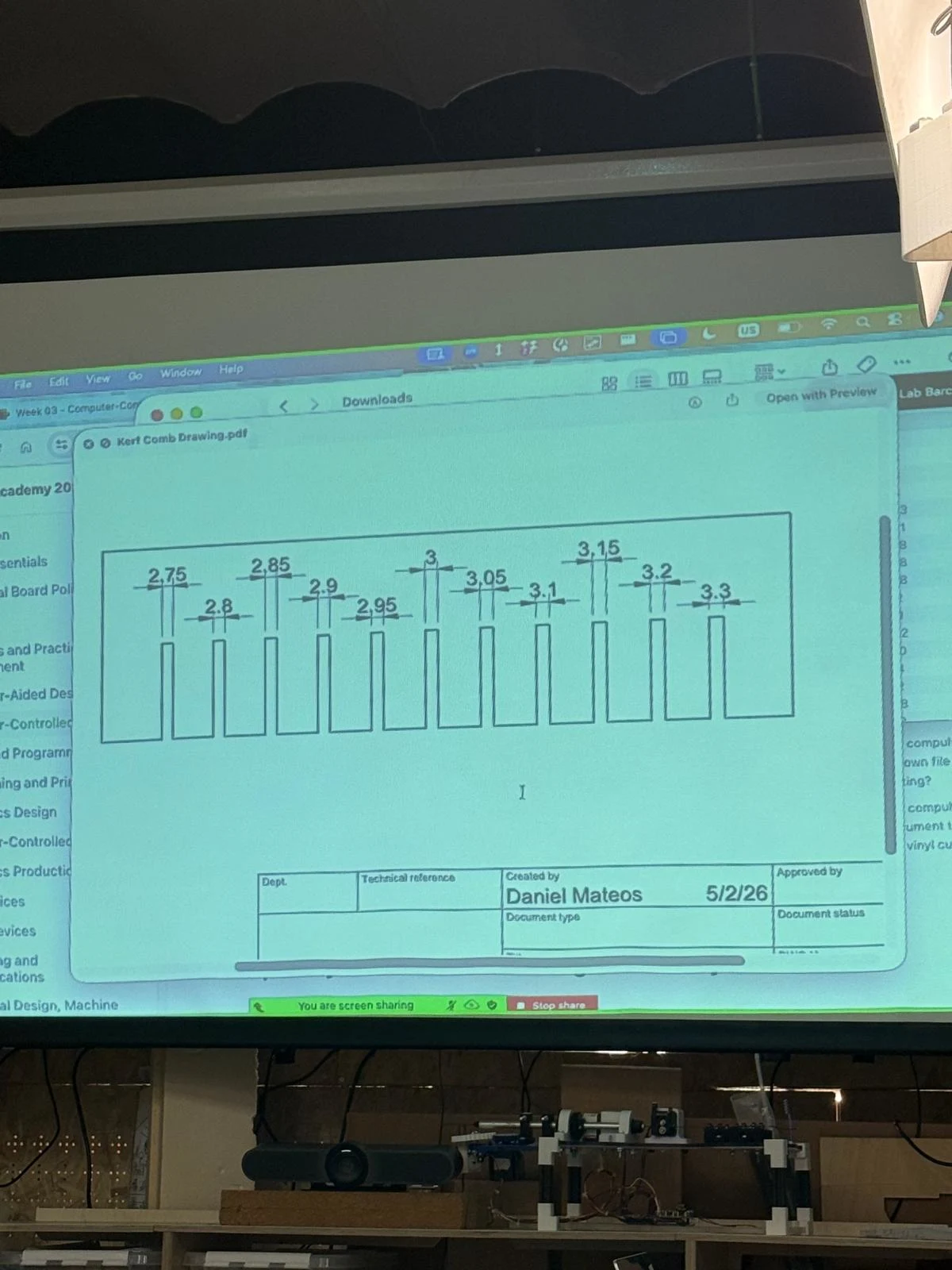
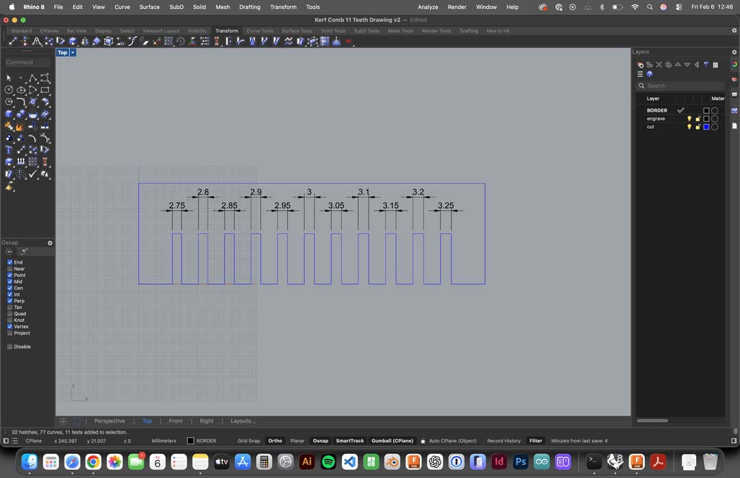
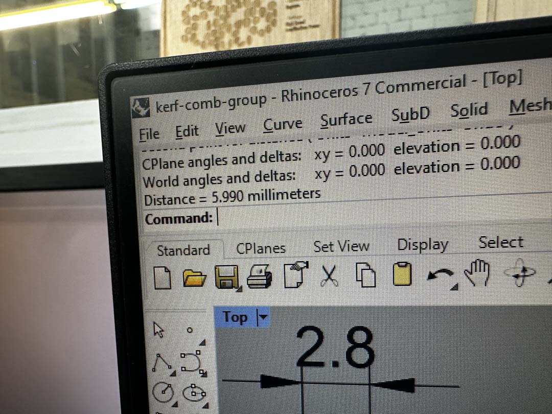
With a 0.05 mm step, the slots range from 2.75 mm to 3.25 mm, which brackets the expected kerf on both sides of the nominal material thickness. The design was then exported and laid out in Rhino for cutting.
Download the design files: Fusion 360 (.f3d) | Rhino (.3dm) | Drawing (.pdf)
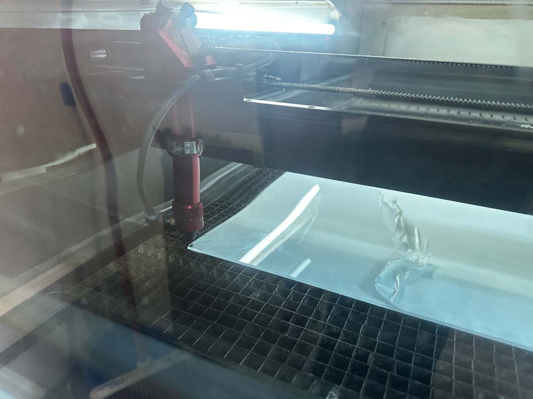
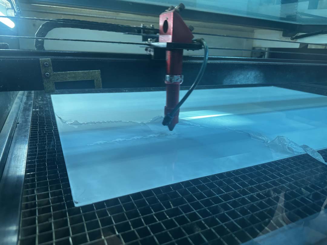
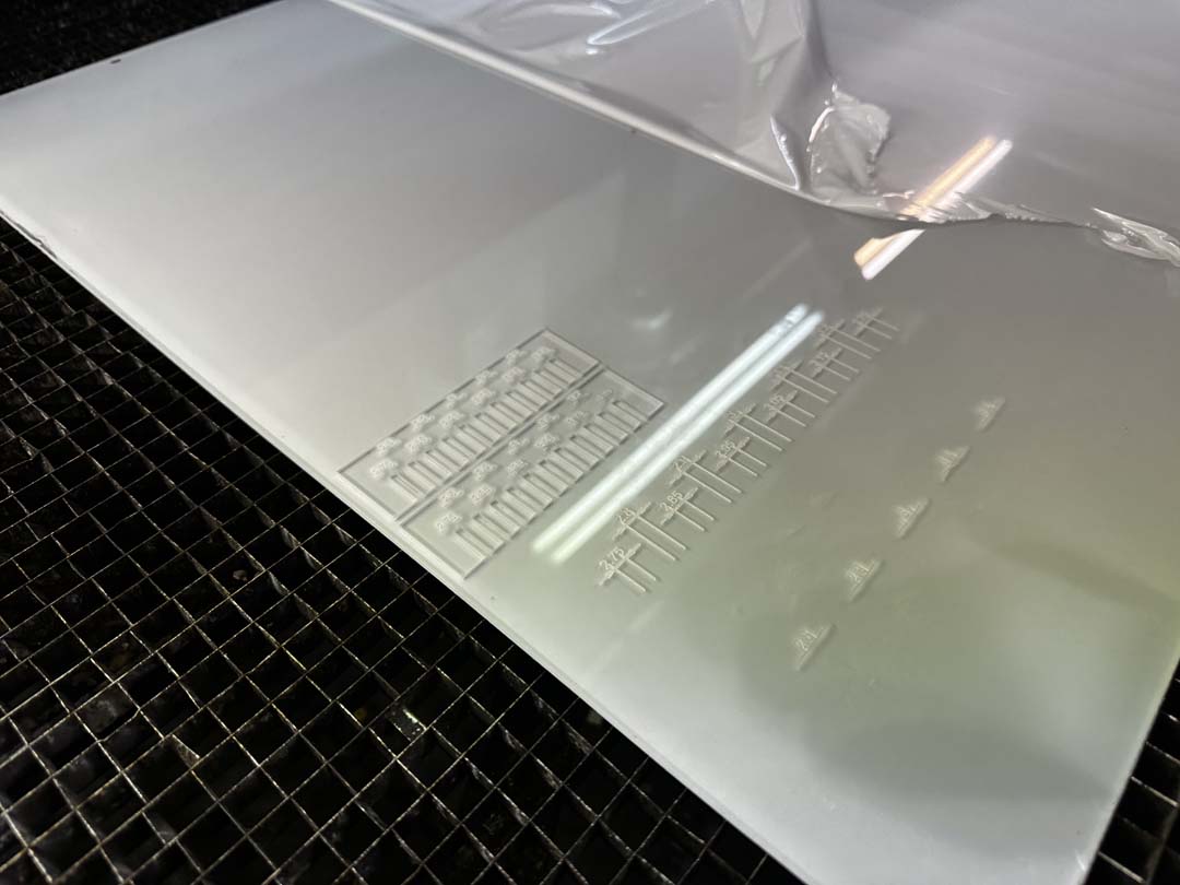
Cutting
We cut the comb on our lab's CO2 laser cutter using 3 mm clear acrylic. We zeroed the XY origin and set the power and speed for the material.

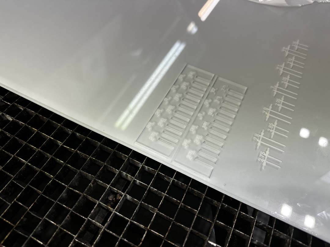
The first cut (v1) revealed a problem: the exported vector file had the wrong dimensions and the comb came out too big.
We fixed the export and re-cut with the correct dimensions (v2). The size difference between the two versions is visible here.
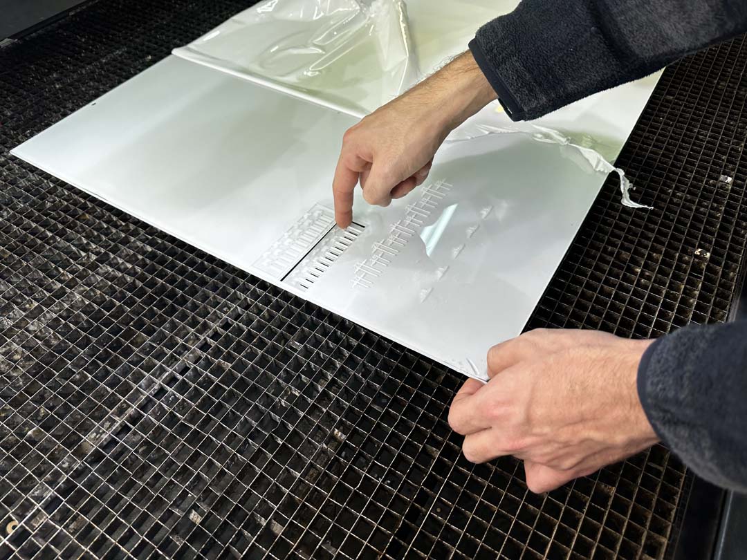
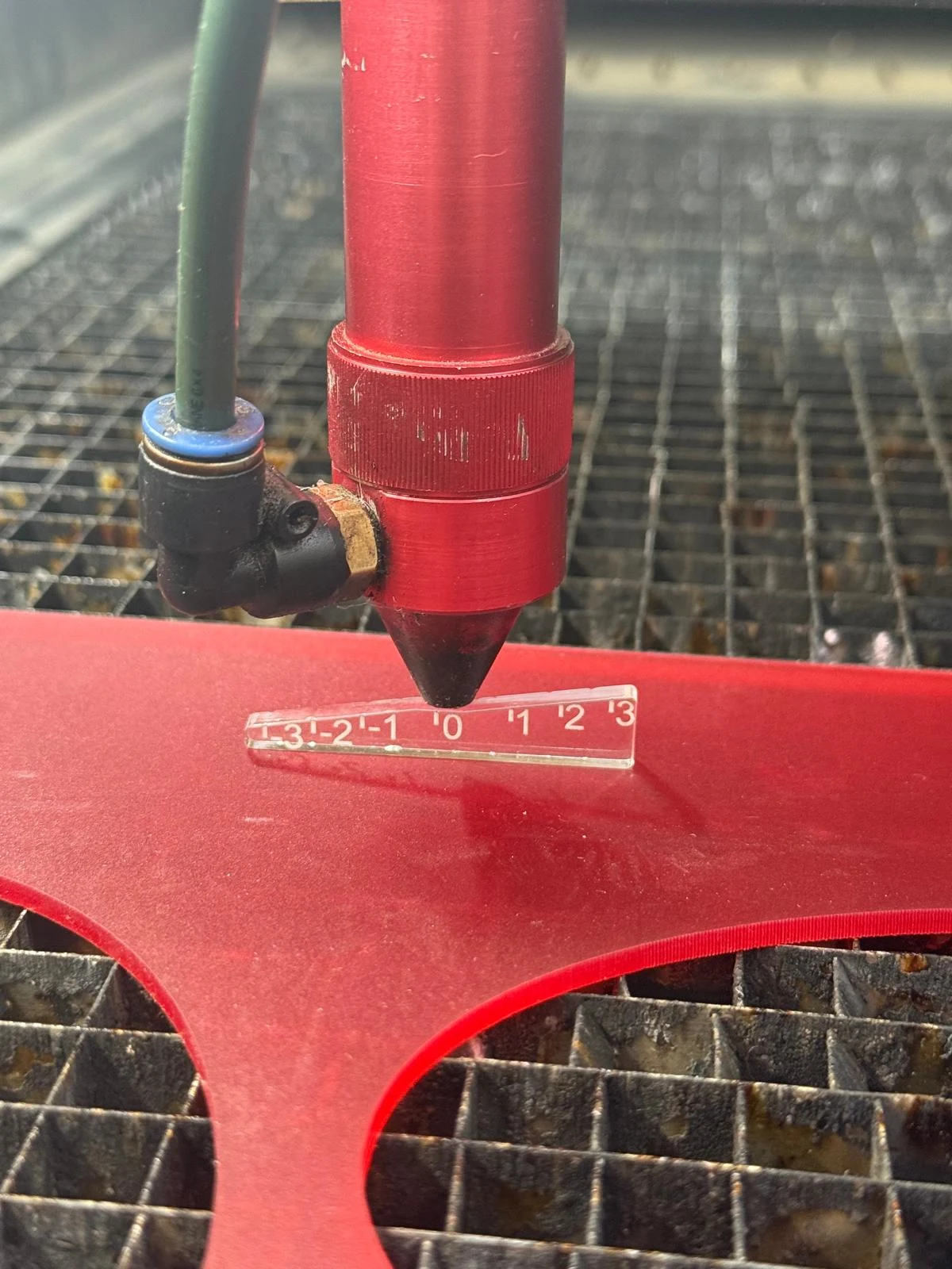
Measuring the Results
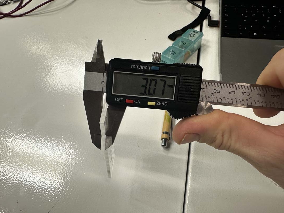
We used digital calipers to measure two things on the finished acrylic comb.
Material thickness: The sheet is nominally 3 mm. Actual measurement: 3.07 mm.
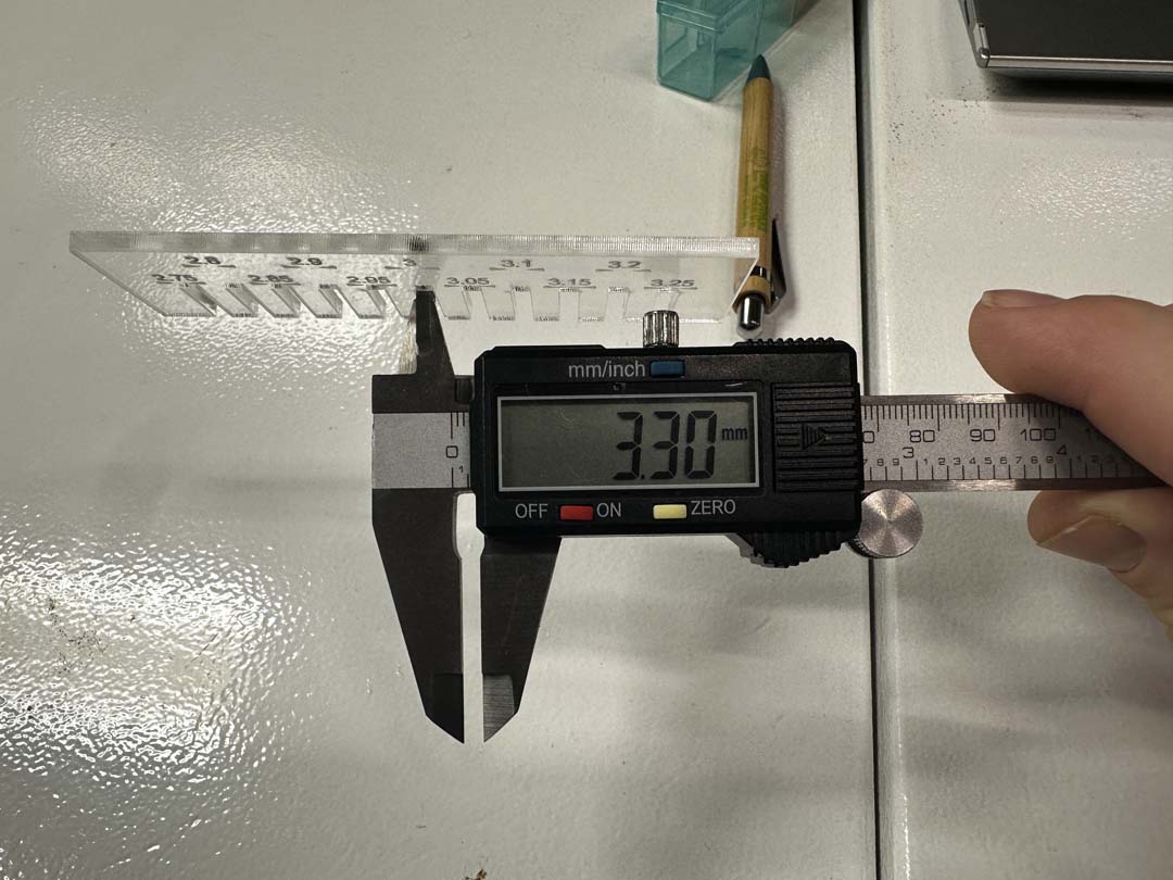
Slot width: We measured the slot designed at 3.00 mm on the cut comb. It came out at 3.30 mm, wider than designed, as expected from kerf.
Results
| Measurement | Value |
|---|---|
| Nominal material thickness | 3.00 mm |
| Measured material thickness | 3.07 mm |
| Measured slot width (designed 3.00 mm) | 3.30 mm |
| Total kerf | ~0.30 mm |
| Kerf per side | ~0.15 mm |
With a kerf of ~0.15 mm per side, we can offset cut lines inward by that amount in Fusion 360 to get press-fit joints that come out the right size.