Week 09 — Input Devices: probing analog and digital signals
During the input devices week, the group explored how to read and measure analog and digital electrical signals using three different tools: a digital multimeter, a portable oscilloscope, and the Arduino IDE Serial Monitor.
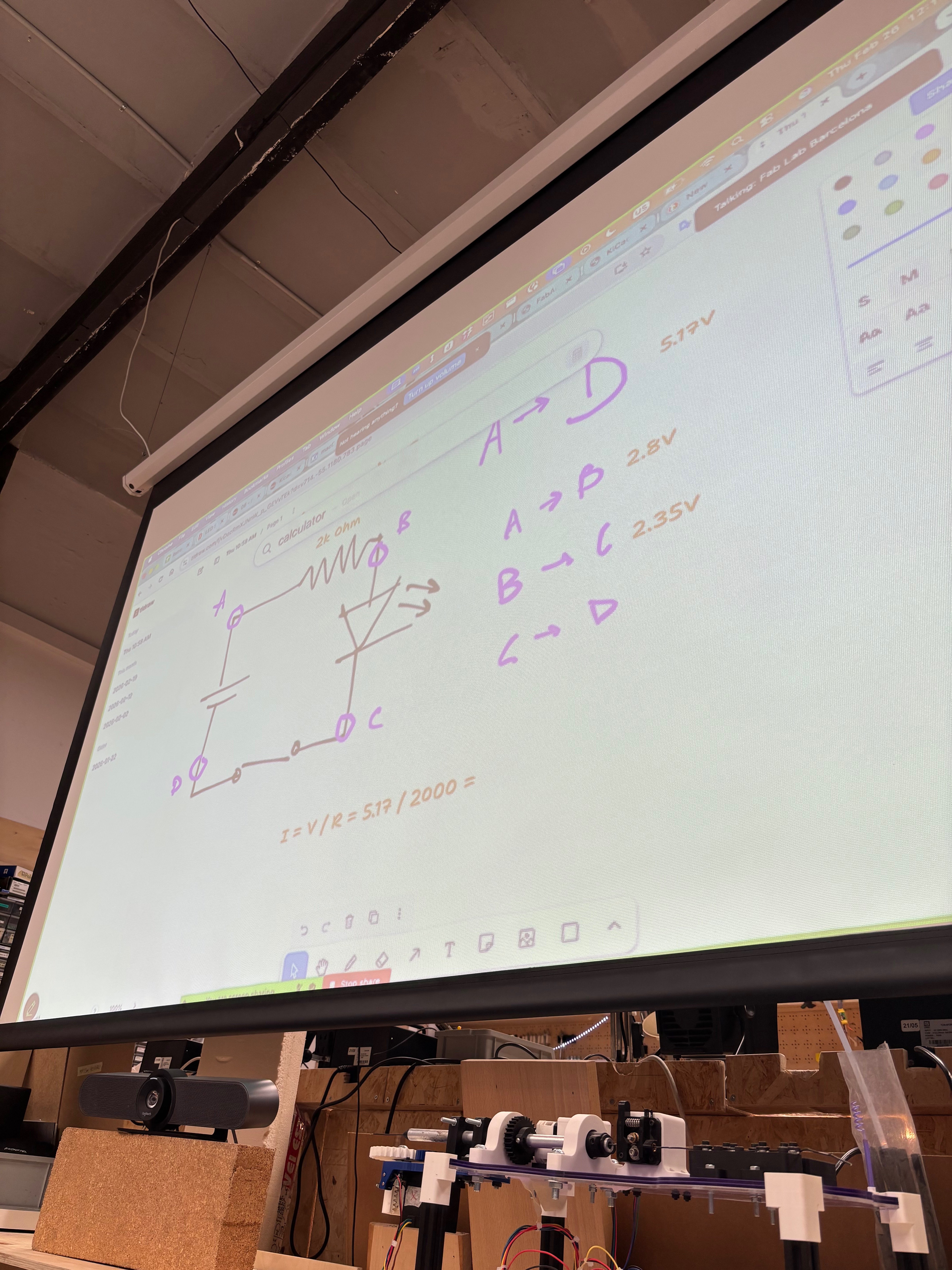
Multimeter measurements on a button circuit
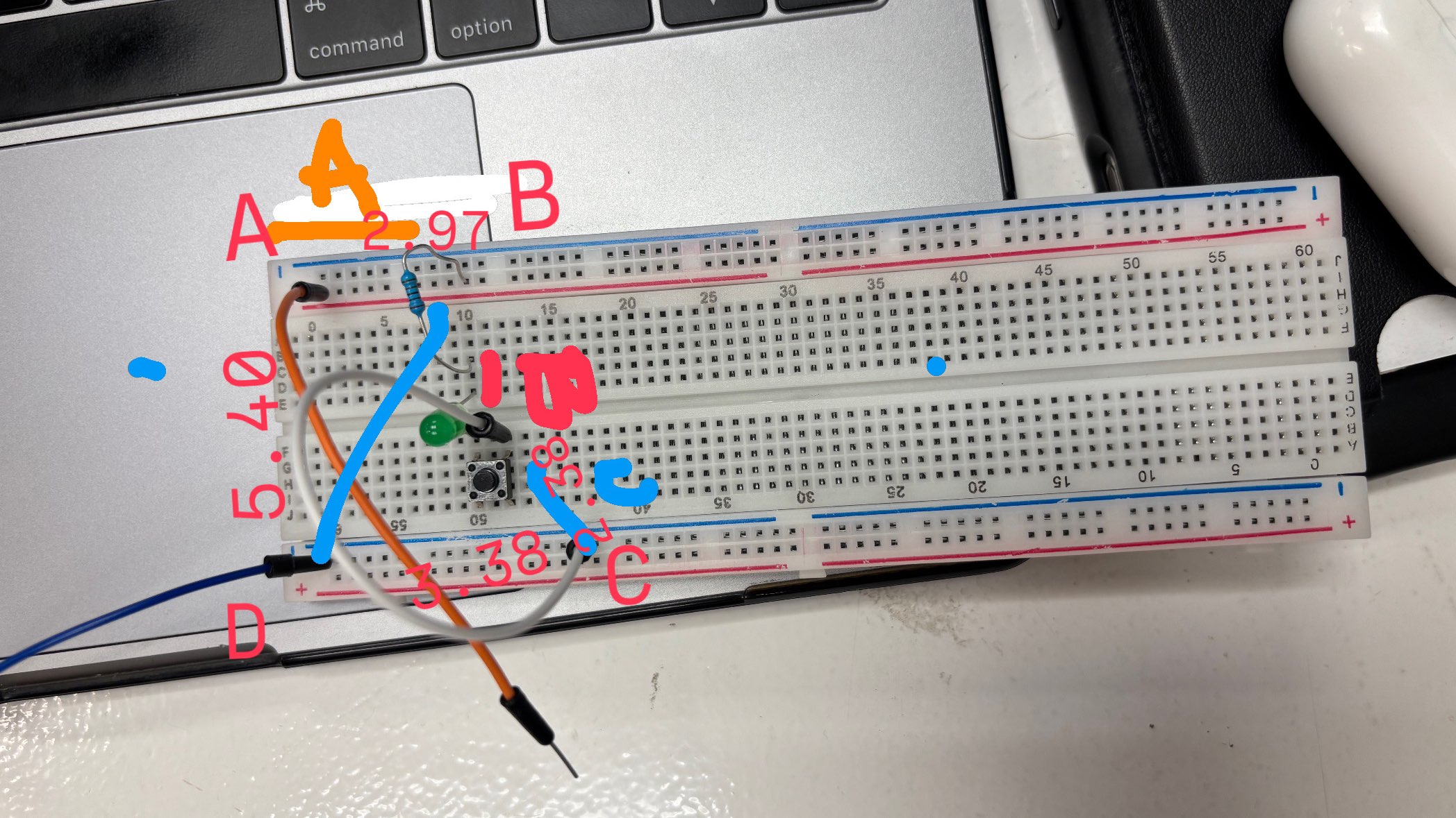
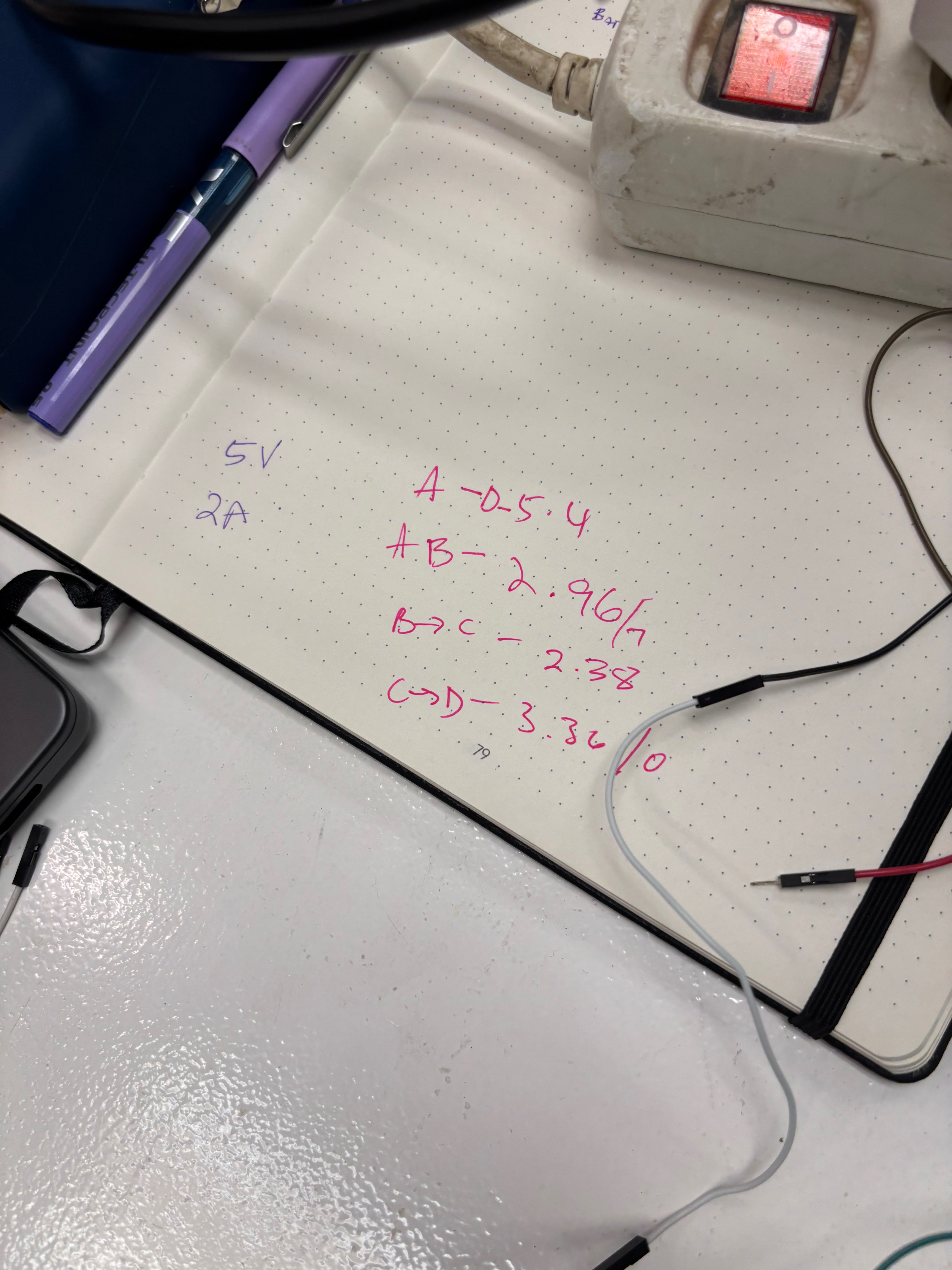
We built a simple circuit on a breadboard with a tactile button, a green LED, and a 2kΩ resistor, powered at 5V/2A. We identified four measurement points — A, B, C, D — and measured the voltage between each one with a CHY A830L digital multimeter.
| Segment | Voltage |
|---|---|
| A | 5.40 V |
| A → B | 2.96 V |
| B → C | 2.38 V |
| C → D | 3.36 V |
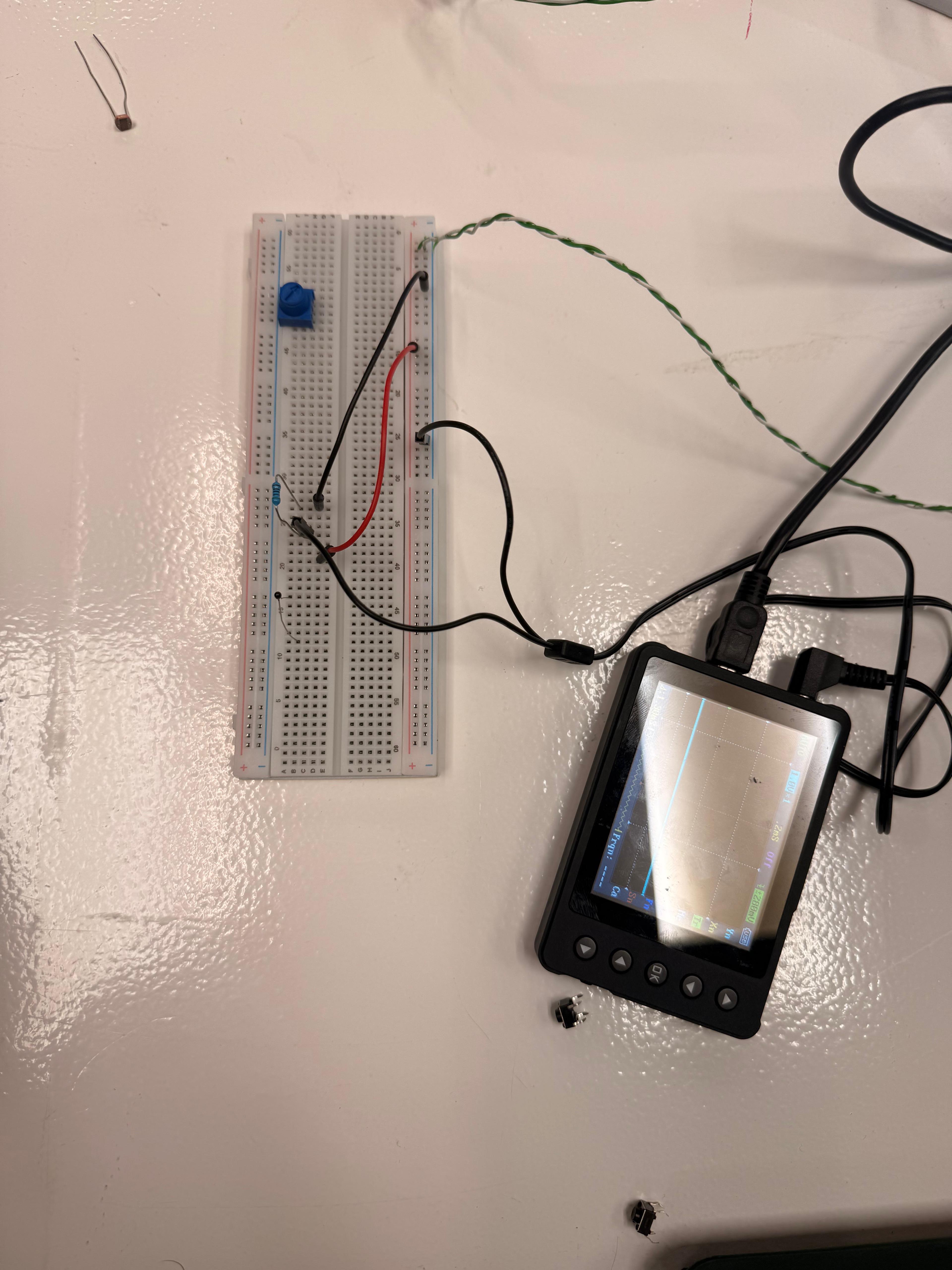
Oscilloscope on the button (digital signal)
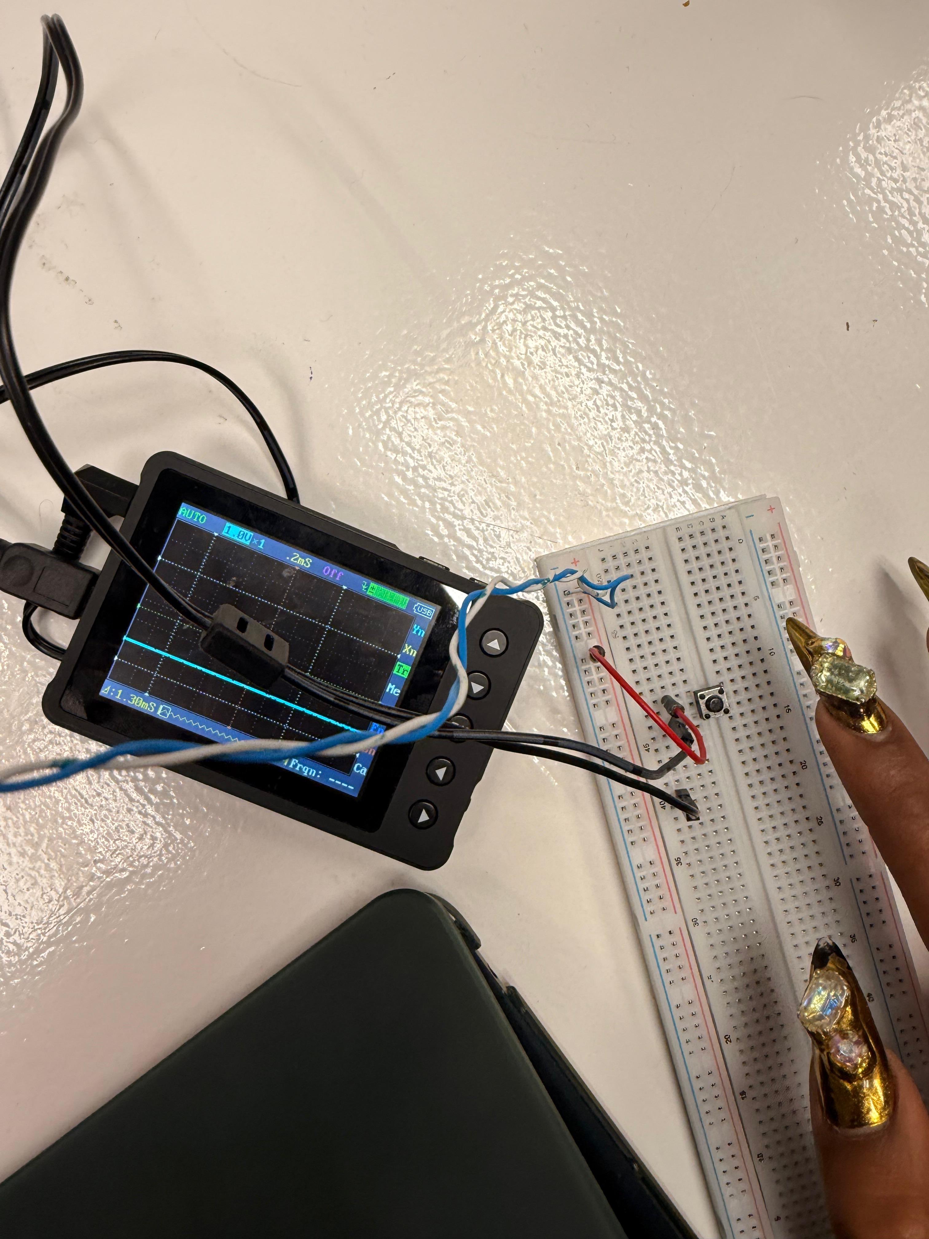
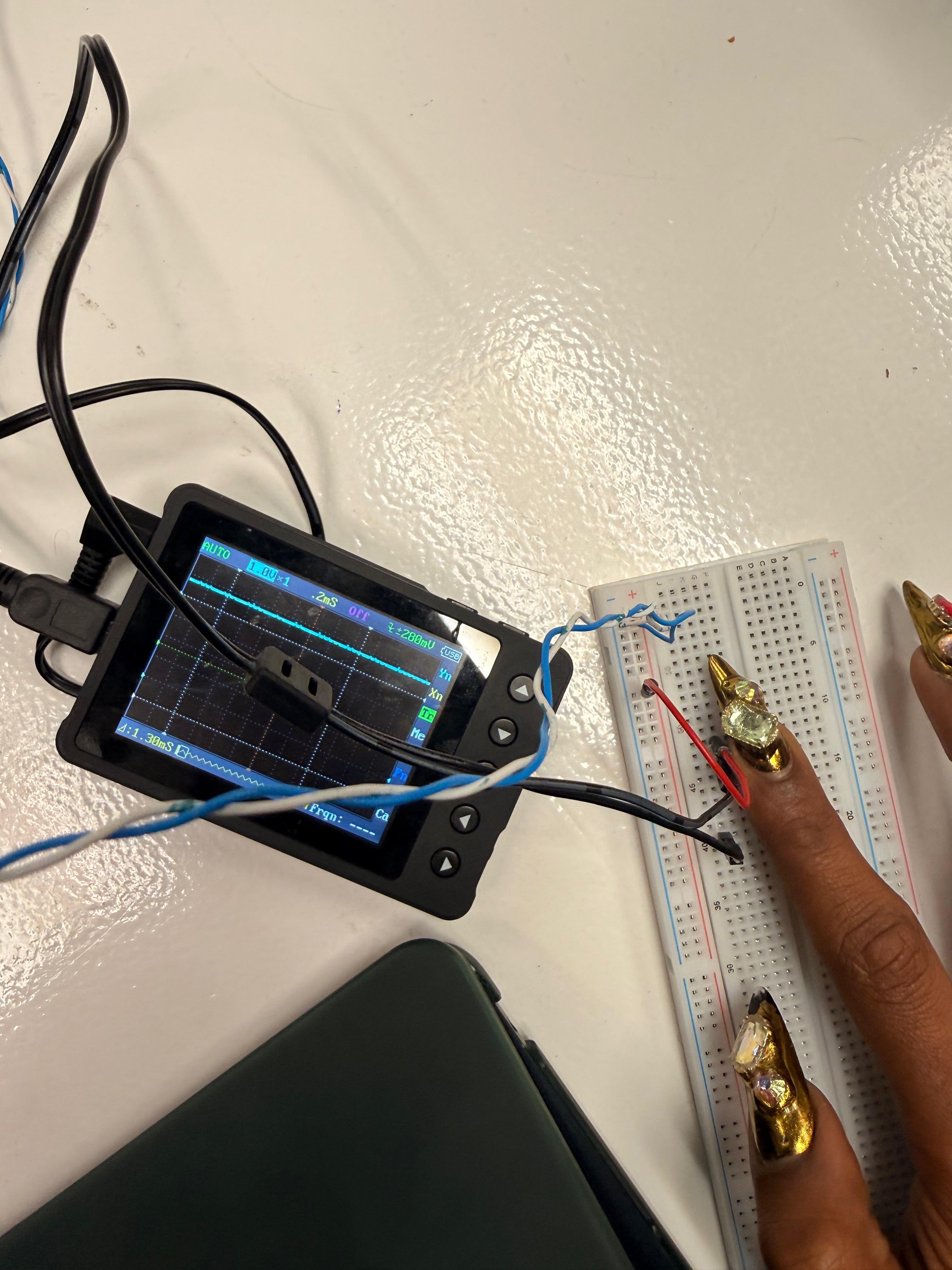
We connected a portable oscilloscope to the button to visualize the digital signal. When the button is released the trace is flat at the bottom; when pressed it rises sharply. The transition is clean and clearly visible at the 2mS scale.
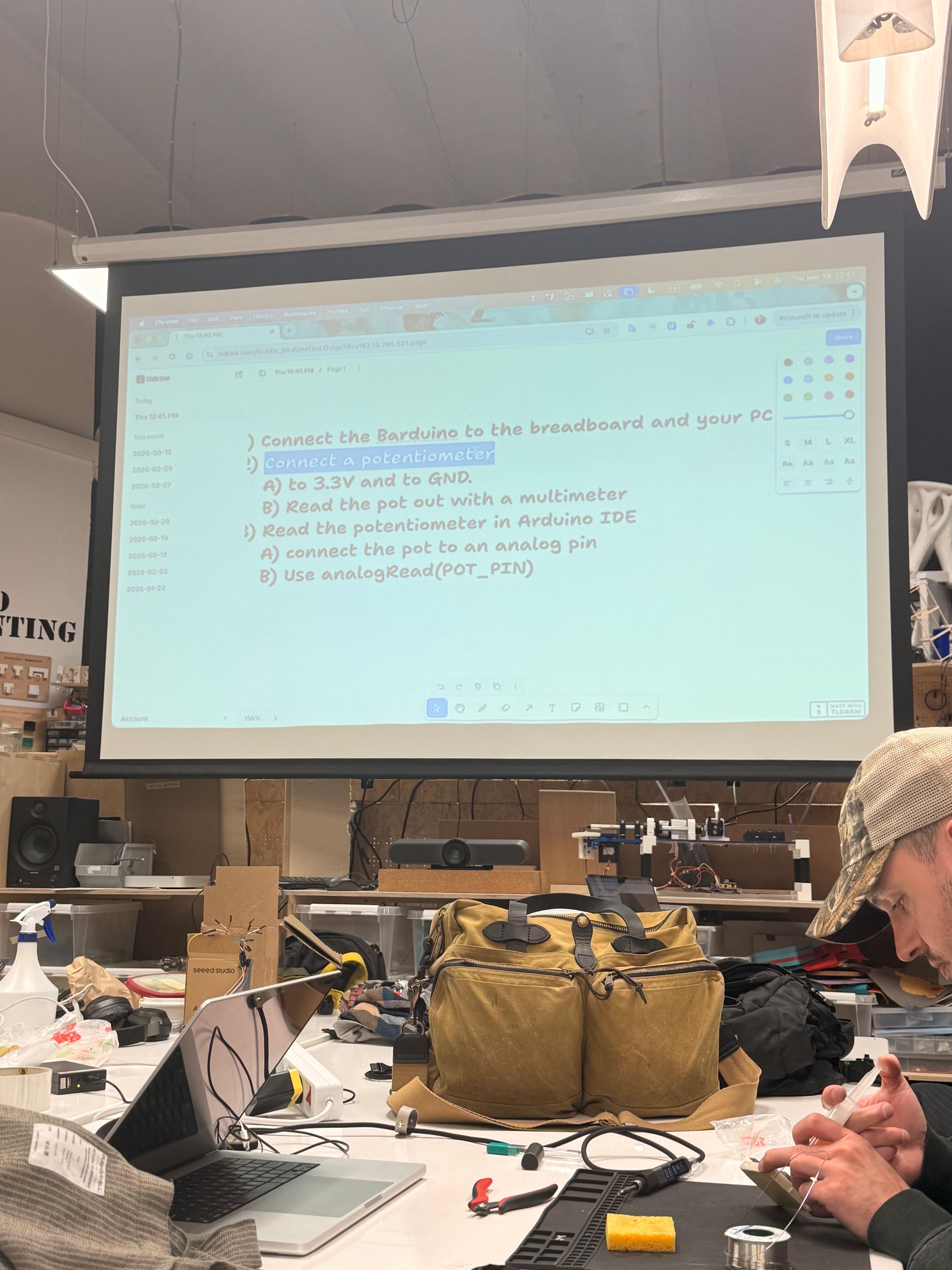
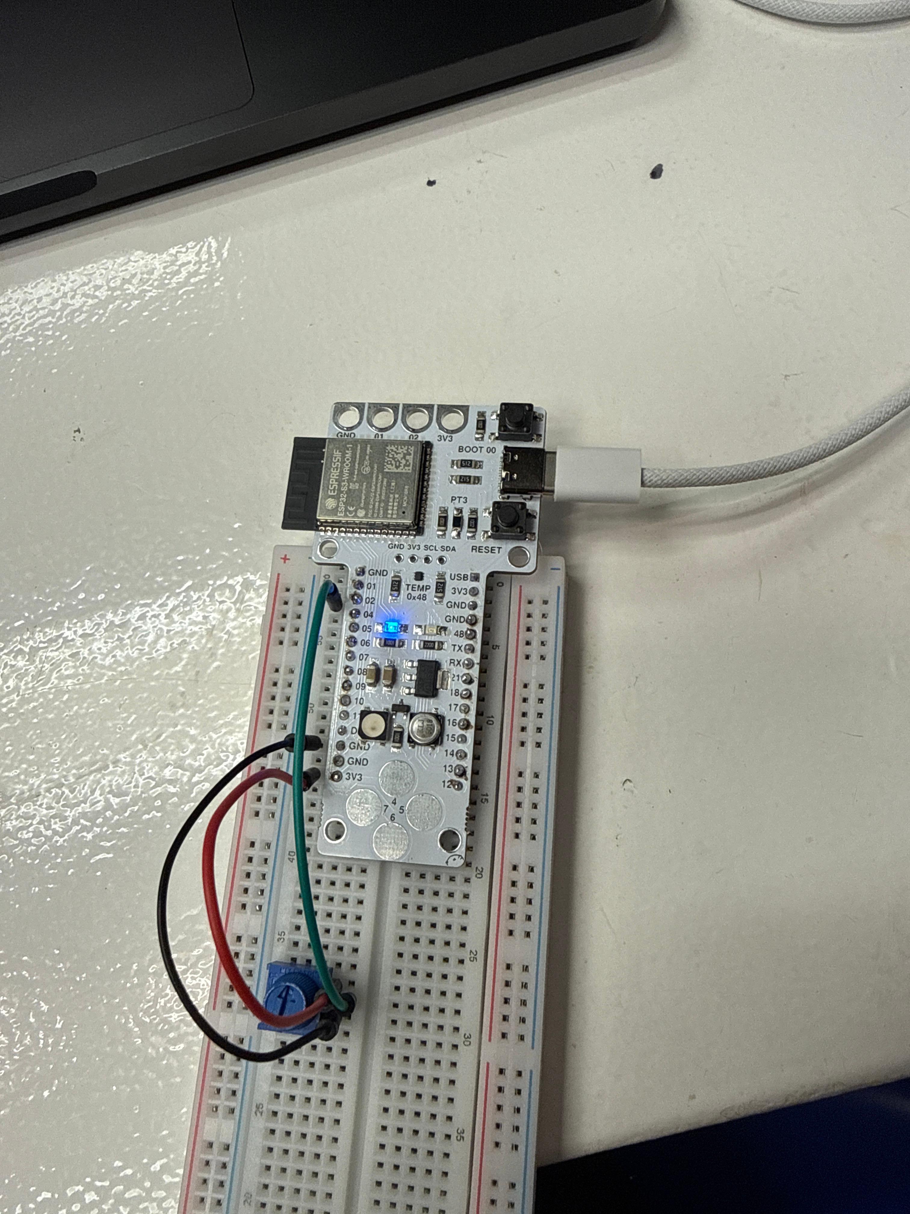
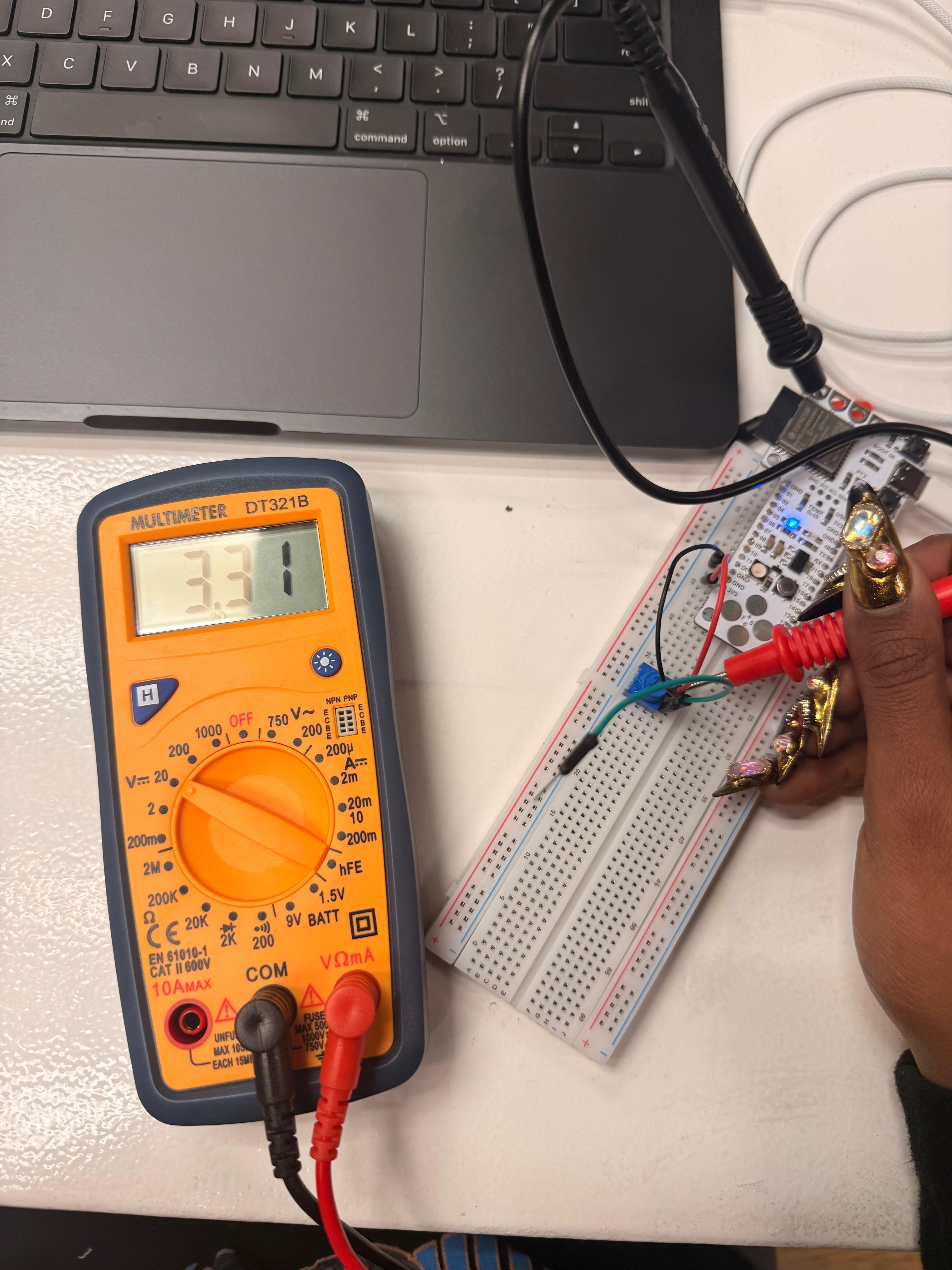
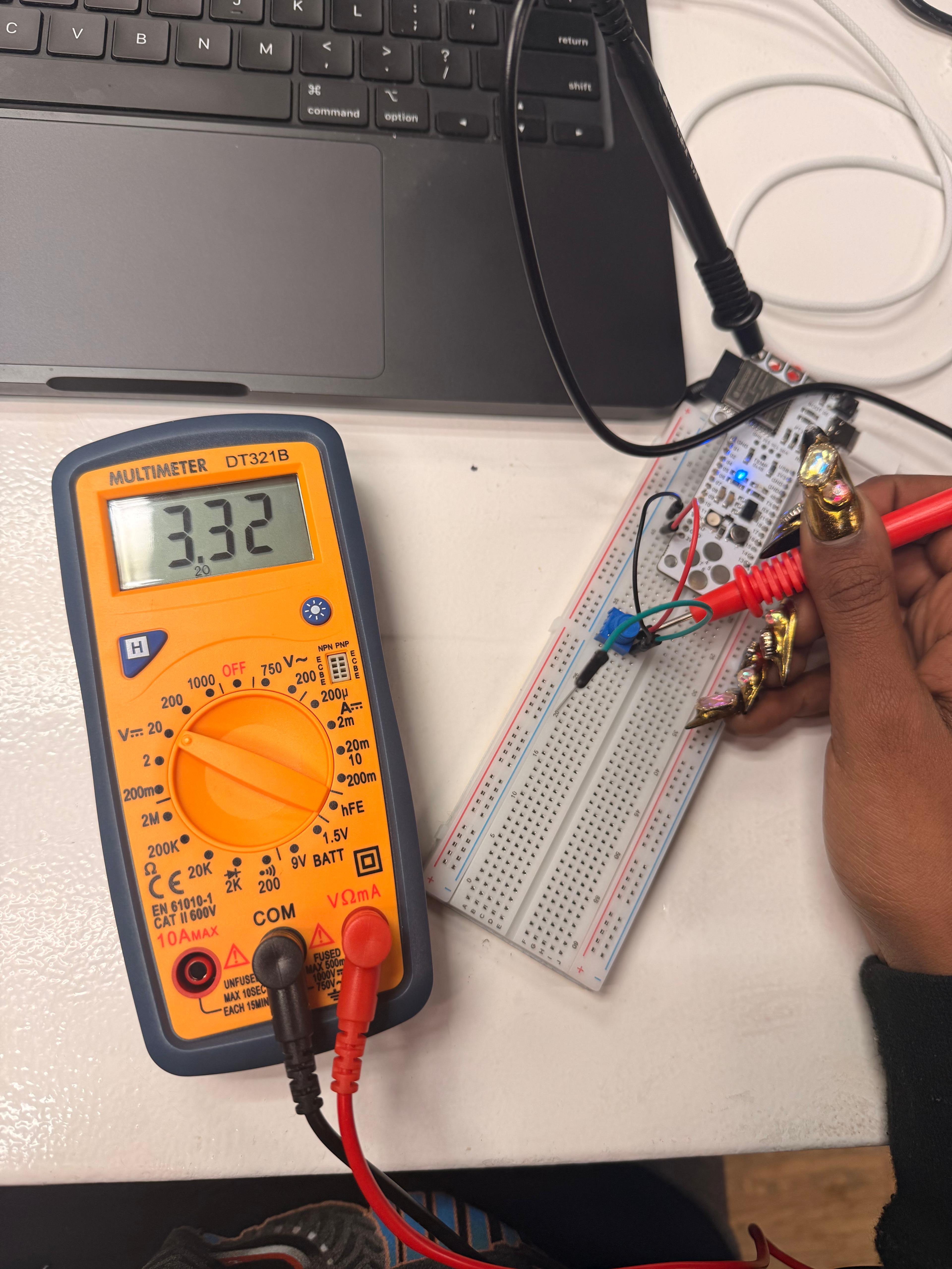
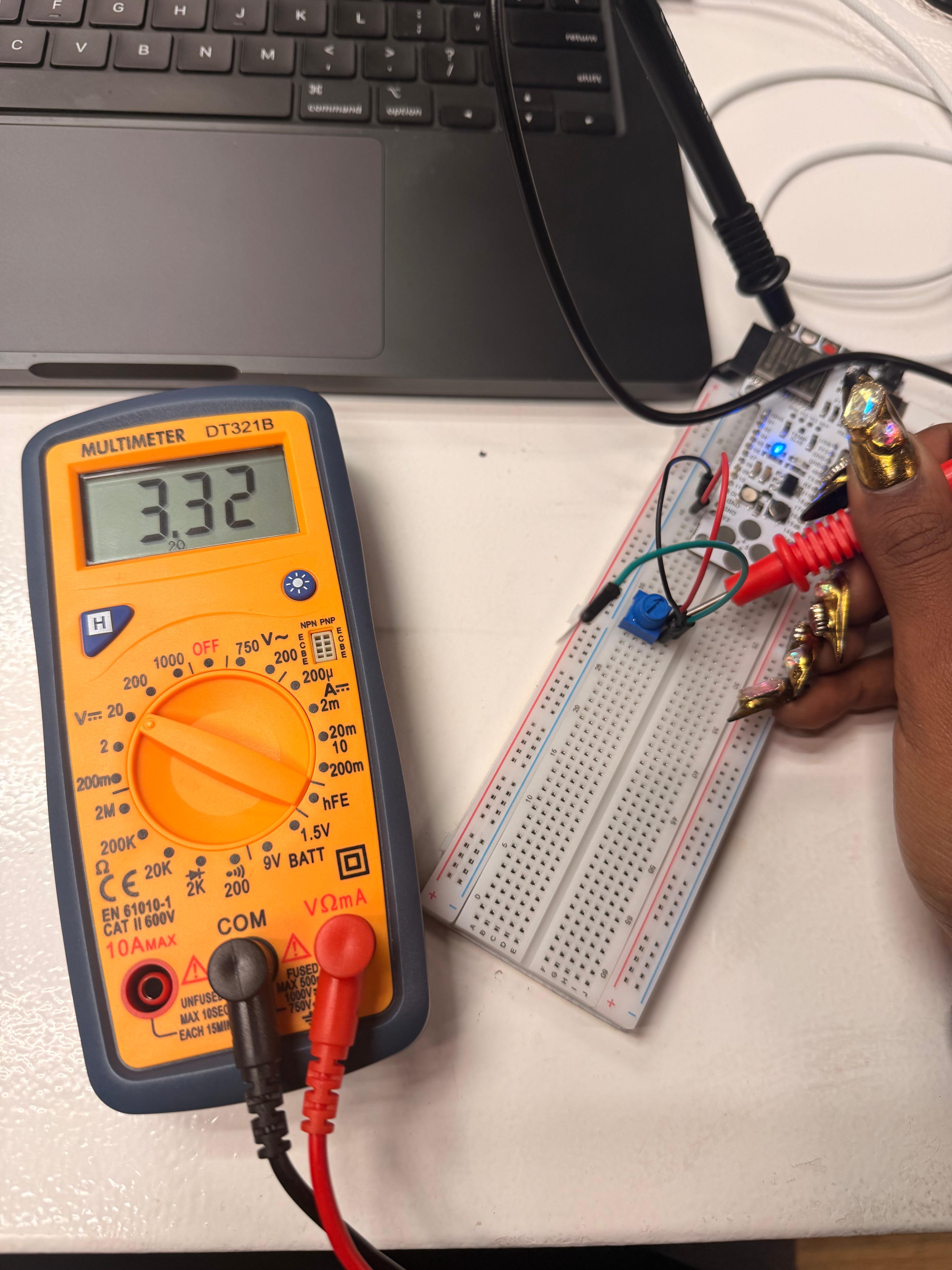
Potentiometer with multimeter and Barduino
Following the instructions projected in class, we connected a blue potentiometer to the Barduino (ESP32-S3): one pin to 3.3V, one to GND, and the center pin to an analog pin. The DT321B multimeter confirmed the supply voltage at 3.31–3.32V.
Serial Monitor — analogRead in real time
With the potentiometer connected to pin A1 of the ESP32-S3, we uploaded a minimal sketch that reads the analog value every 200ms and prints it to the Serial Monitor. Rotating the potentiometer changes the value in real time between 0 and 4095 (12-bit ADC). The video shows the value at 3405.
int potPin = A1;
int potValue = 0;

void setup() {
  Serial.begin(115200);
}

void loop() {
  potValue = analogRead(potPin);
  Serial.println(potValue);
  delay(200);
}