Week 8 - Electronics Production (PCB Milling Characterization)
Group Assignment
The goal of this group assignment was to characterize the PCB milling process.
We focused on:
- Understanding machine setup and workflow
- Identifying design rules (trace width, spacing, tool limits)
- Comparing different milling tools
- Establishing a reliable fabrication pipeline
Machine Setup and Preparation
Before starting the milling process, we prepared the machine and materials to ensure accuracy and repeatability.
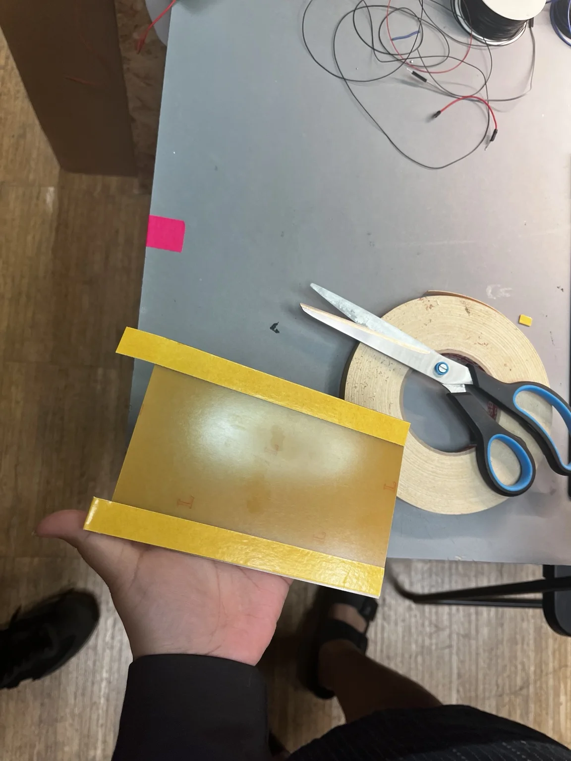
We fixed the copper-clad board onto a sacrificial layer using double-sided tape. Proper adhesion is critical to avoid uneven milling depth.
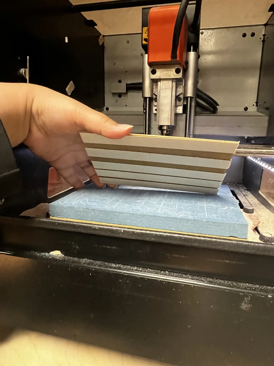
A flat and stable sacrificial surface was used to ensure consistent Z-depth across the board.
Cleaning and Surface Preparation
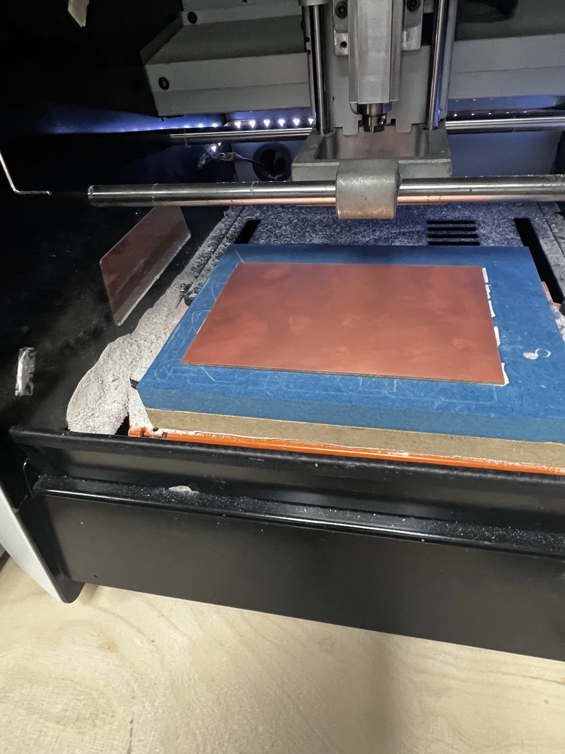
We cleaned the machine bed and surrounding area to remove dust and debris. Any particles can affect the milling precision and tool stability.
Tooling Comparison
The main goal of this test was to compare different milling tools:
- 1/64" flat end mill
- V-bit 15°
- V-bit 30°
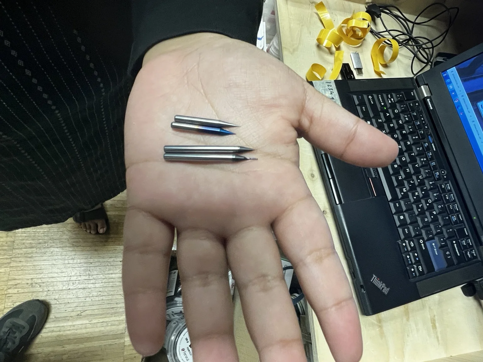
Each tool has different characteristics:
- 1/64" end mill → consistent trace width, limited resolution
- 15° V-bit → higher resolution, variable width depending on depth
- 30° V-bit → more robust but lower precision than 15°
Tool Installation

We manually installed the milling bit and secured it in the spindle. Care was taken to:
- Ensure proper tightening
- Avoid tool misalignment
- Keep minimal tool stick-out for stability
Machine Control Setup
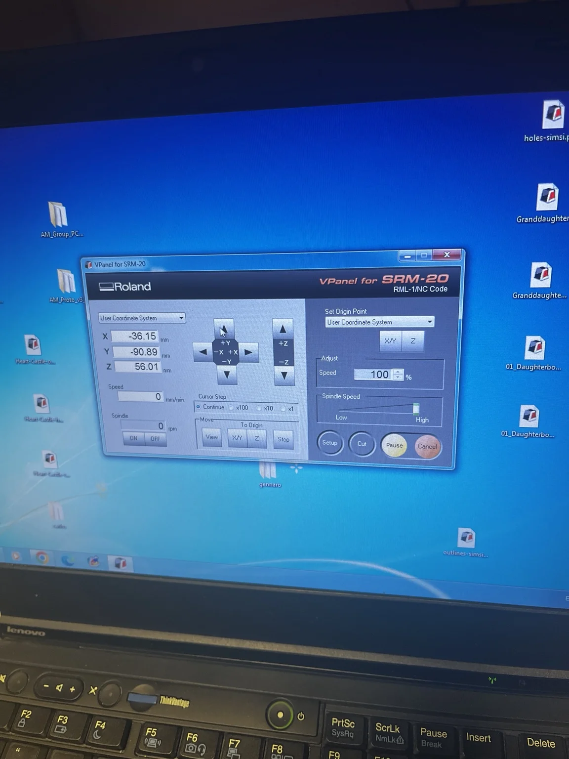
Using Roland VPanel:
- Set XY origin manually
- Adjust Z height carefully using incremental steps
- Defined the work origin on the copper surface
Z calibration is the most critical step — small errors directly affect trace quality.
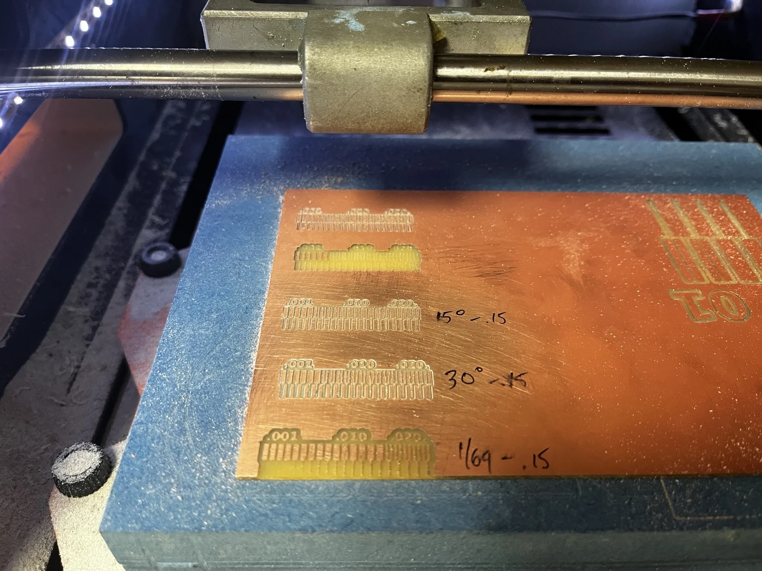
Test File: Line Test
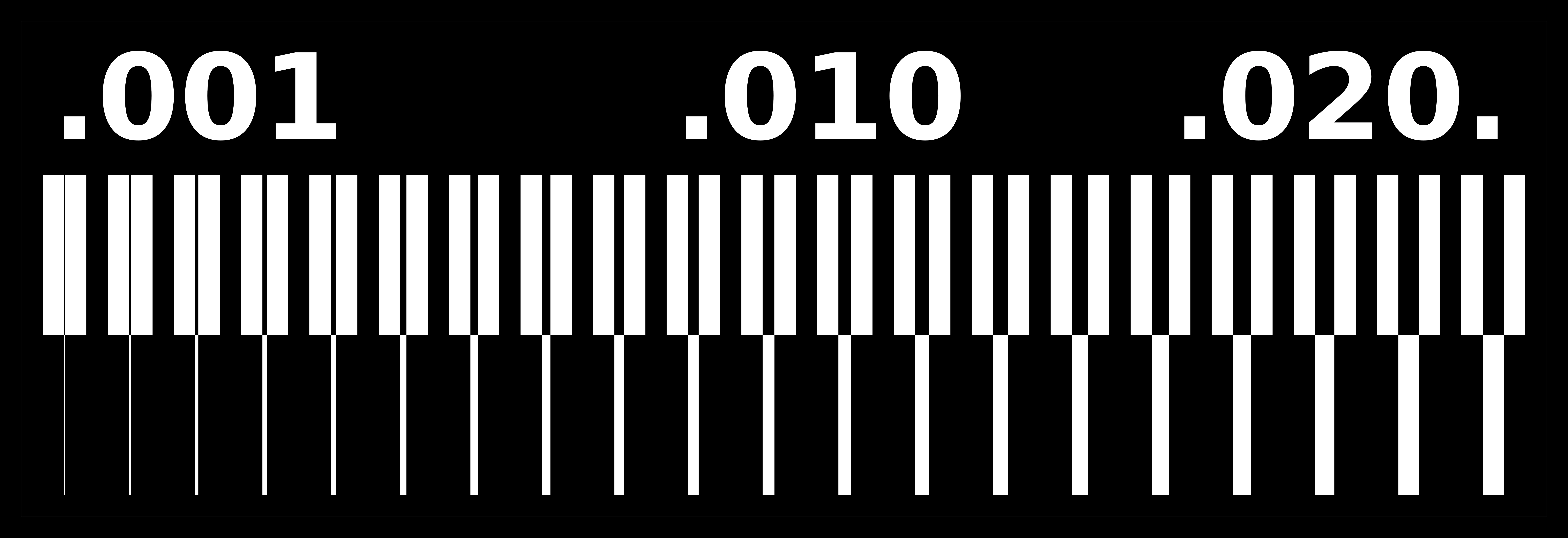
We used the linetest.traces file to evaluate:
- Minimum trace width
- Trace spacing capability
- Tool resolution limits
This test is essential for defining PCB design rules.
First Milling Results
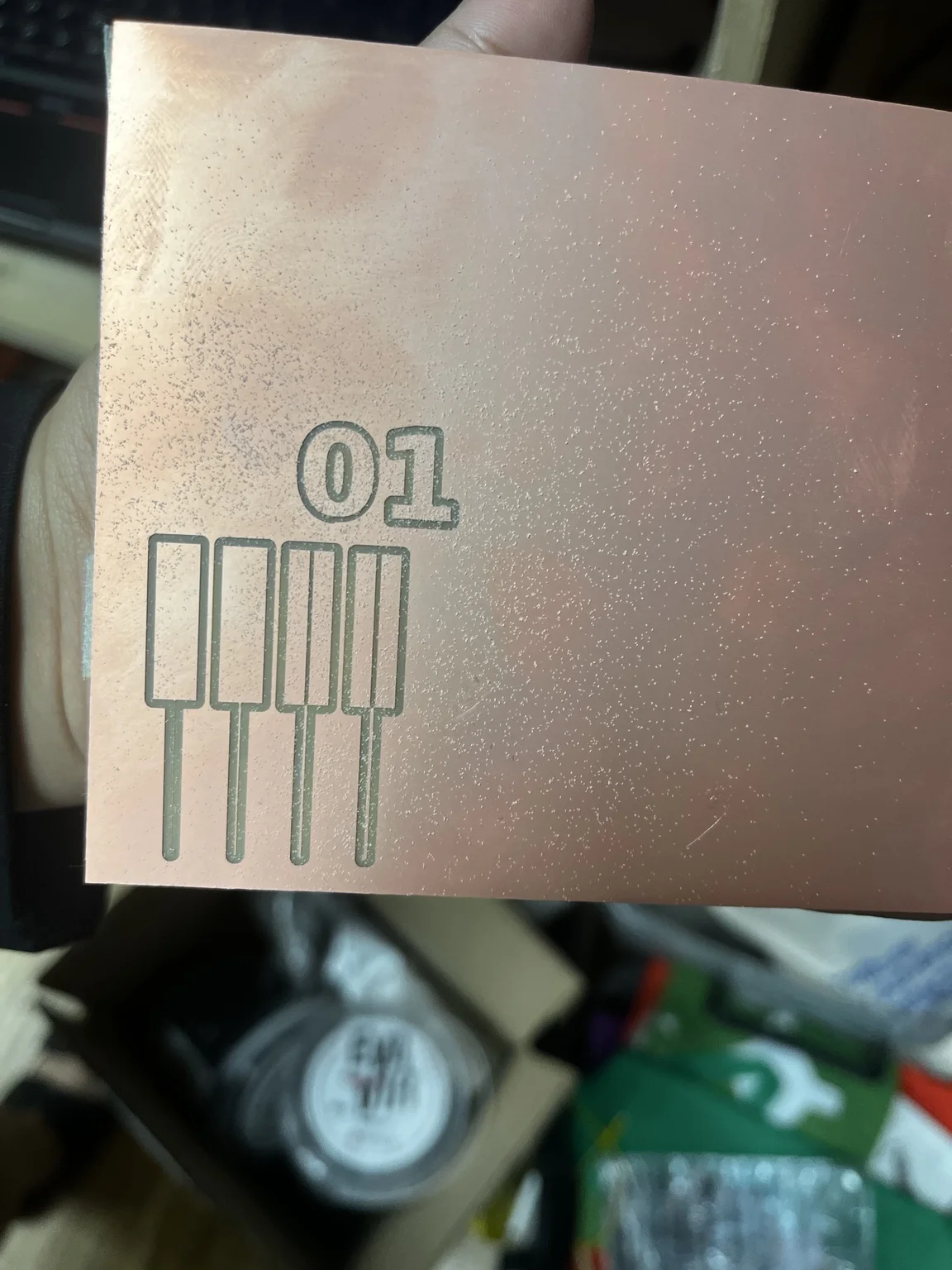
Traces were super big, so we had to go back and check settings, concluding that it had to do with the image file.
Toolpath Generation in Mods
Input File Setup
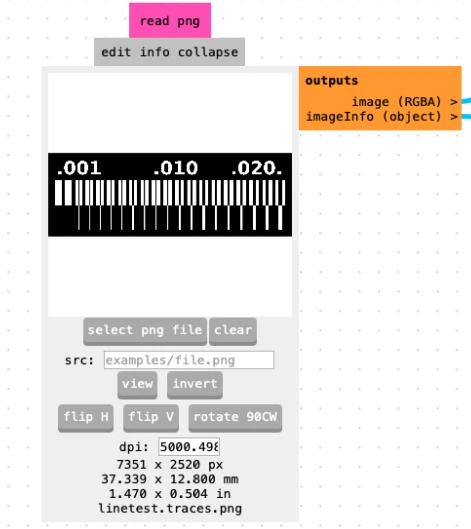
We imported the line test PNG file into Mods. The file resolution was:
- DPI: 5000
- This value is critical for correct scaling
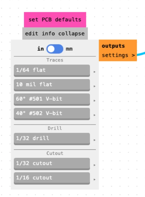
Raster Milling Settings
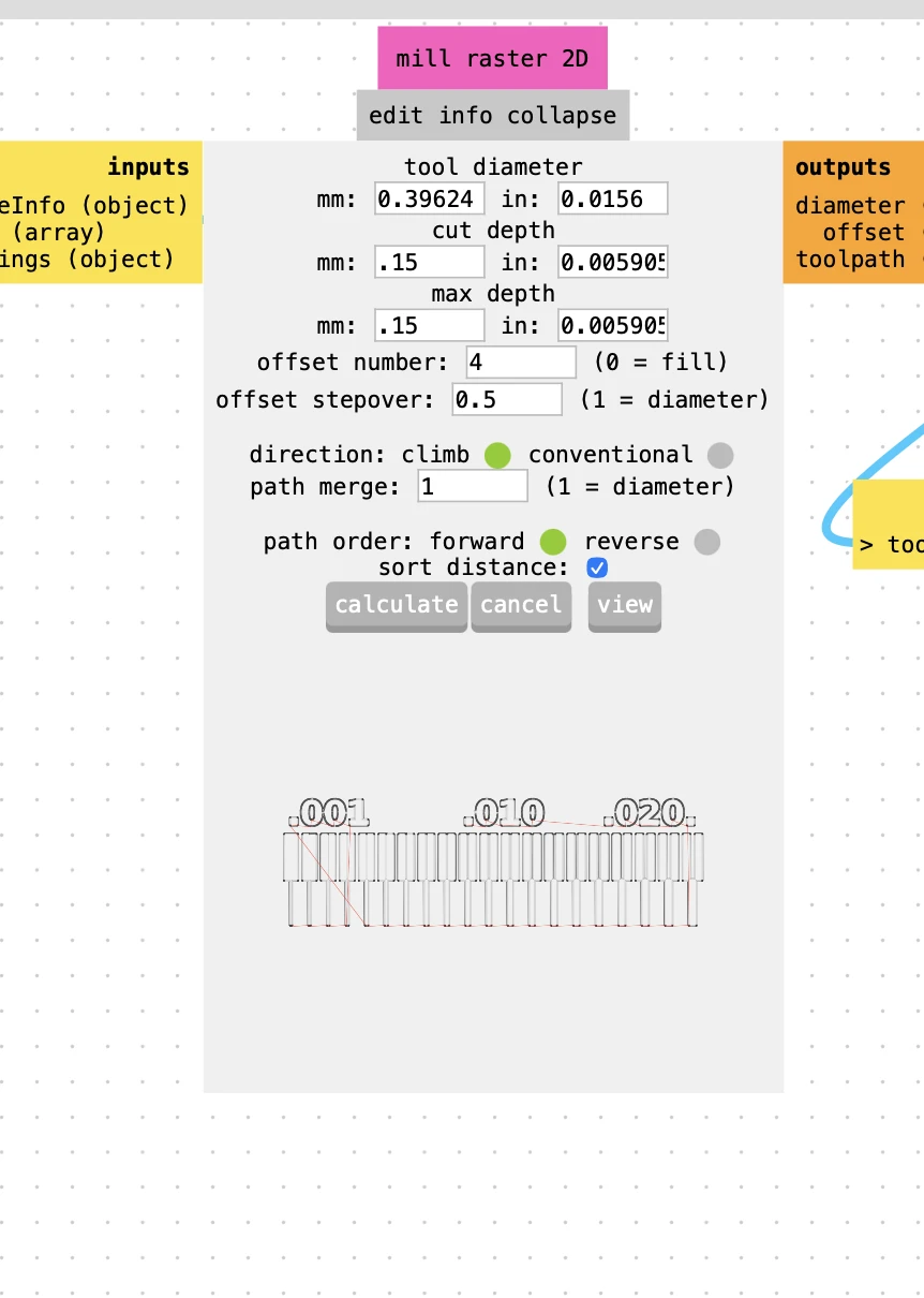
We configured the mill raster 2D module:
- Tool diameter: calculated based on tool
- Cut depth: 0.15 mm
- Max depth: 0.15 mm
- Offset number: 4
- Offset stepover: 0.5
- Direction: climb
- Path merge: 1
These settings define how the copper is removed around traces.
Machine Output Settings
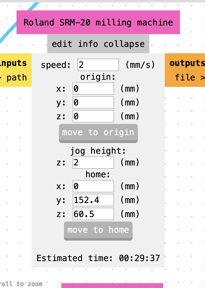
For the Roland SRM-20:
- Speed: 2–4 mm/s
- Origin: manually set on machine
- Jog height: 2 mm
Make sure this is toggled:
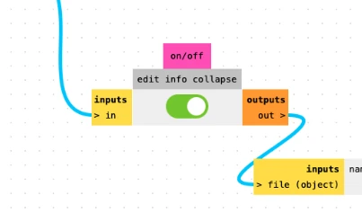
V-Bit Tool Configuration
To properly use V-bits, we used the V-bit calculator inside Mods.
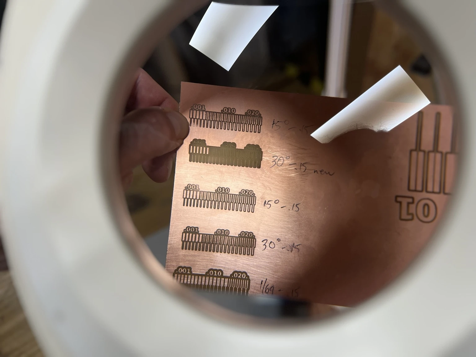
15° V-Bit Settings

- Tip diameter: 0.1 mm
- Angle: 15°
- Cut depth: 0.15 mm
- Resulting cut width: ~0.139 mm
30° V-Bit Settings
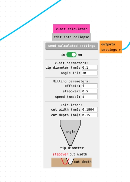
- Tip diameter: 0.1 mm
- Angle: 30°
- Cut depth: 0.15 mm
- Resulting cut width: ~0.180 mm
1/64" End Mill Settings
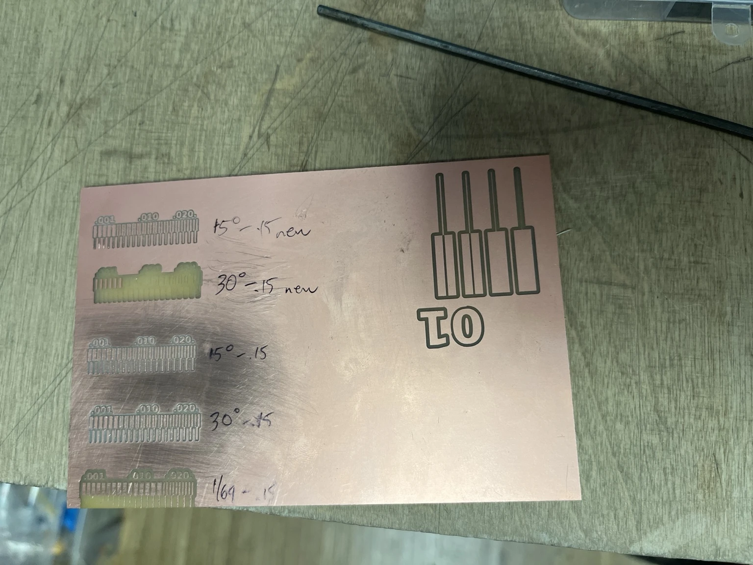
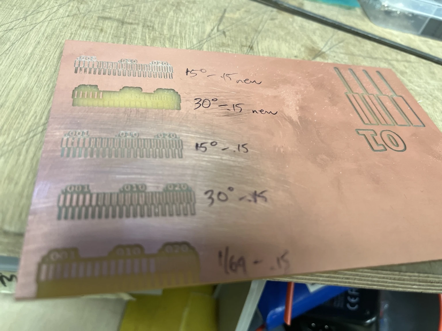
Final Comparison Results
Final Learnings
Through this process, we learned that attention to detail is critical in PCB production. Small parameters such as DPI, tool geometry, and Z calibration have a direct and significant impact on the final result.
Each step in the workflow requires correct and consistent settings, from file preparation in Mods to machine configuration. A mismatch in any parameter (such as DPI) can lead to incorrect scaling or poor milling quality.
We also observed that results are often different from expectations. While V-bits theoretically allow for higher precision, in practice they were more sensitive to setup conditions. In our case, the V-bits did not produce results as clean or reliable as expected this time around.
In contrast, the 1/64" end mill proved to be more predictable and robust, offering more consistent results.
Although the results were not perfect, the process provided valuable insights that helped us define a more reliable and repeatable PCB production workflow.