Week 6 - Electronics Design
Group Assignment
We decided to actuate our installation using three stepper motors using the Barduino.
Main Components:
Stepper Model: 28BYJ-48 / 5V DC
DataSheet Site
https://www.alldatasheet.com/view.jsp?Searchword=28byj%2048%2012v
Motor Driver: ULN2003 Driver
https://www.hadex.cz/spec/m513.pdf
Controller: Barduino
Description of the Basic Set-up
The 28BYJ-48 is already connected to the ULN2003 Driver. This saves us time in calibrating the driver to the voltage needs of the stepper, which is usually done through a trimmer in other driver models.
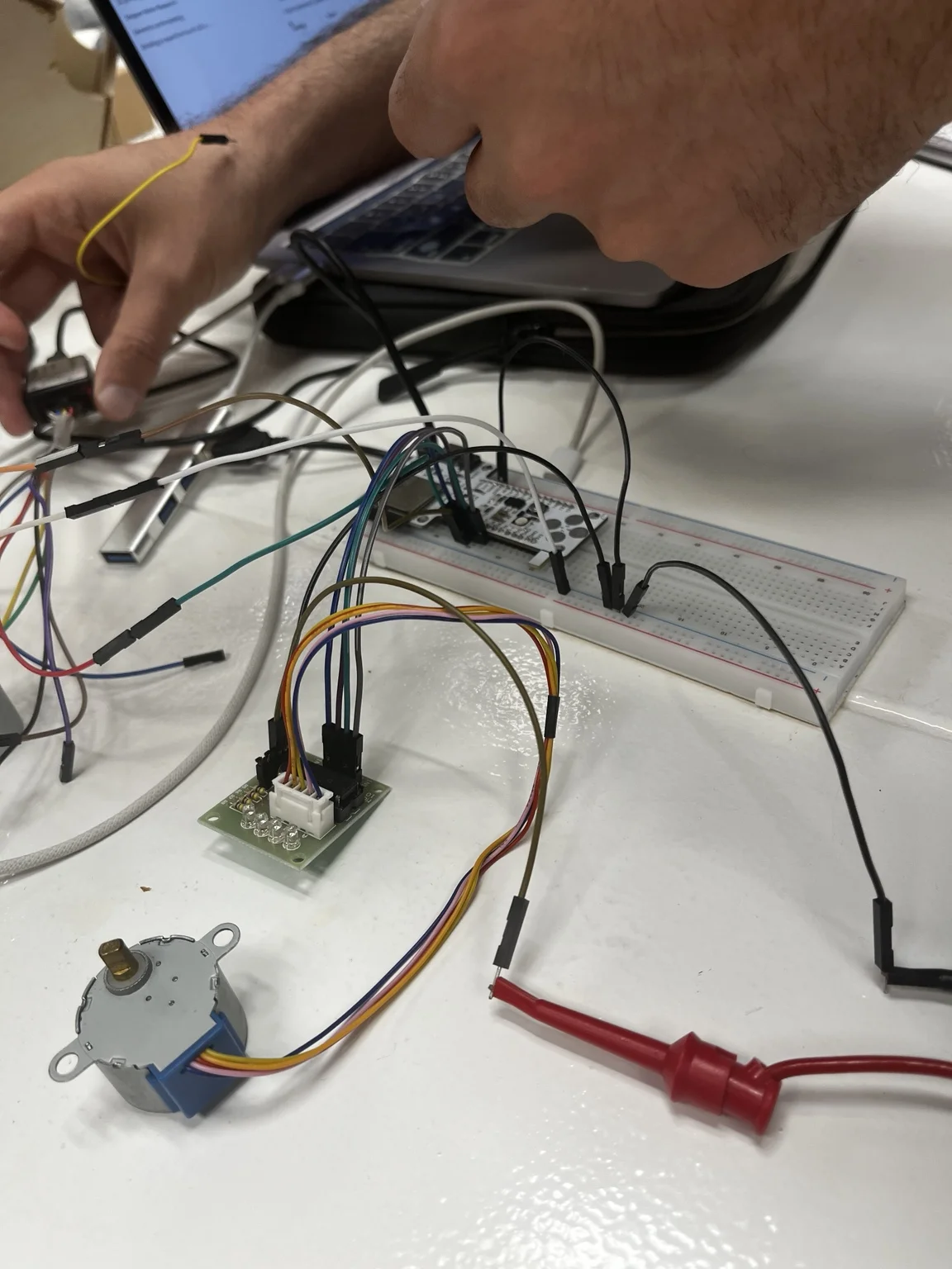
Setup Overview:
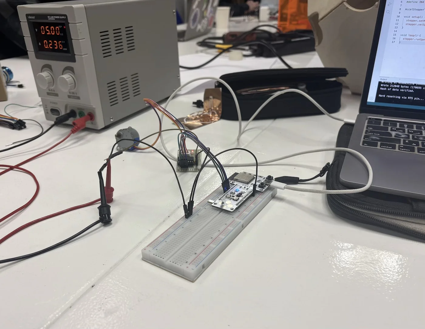
The full system consists of:
- Barduino microcontroller on breadboard
- ULN2003 driver board with integrated LEDs
- 28BYJ-48 stepper motor
- External power supply
We verified that:
- The LEDs on the driver board reflect the activation of each coil
- Each LED corresponds directly to one of the control pins (IN1–IN4)
- This provides a quick visual debugging method before using the logic analyzer
Driver + Motor Connection:
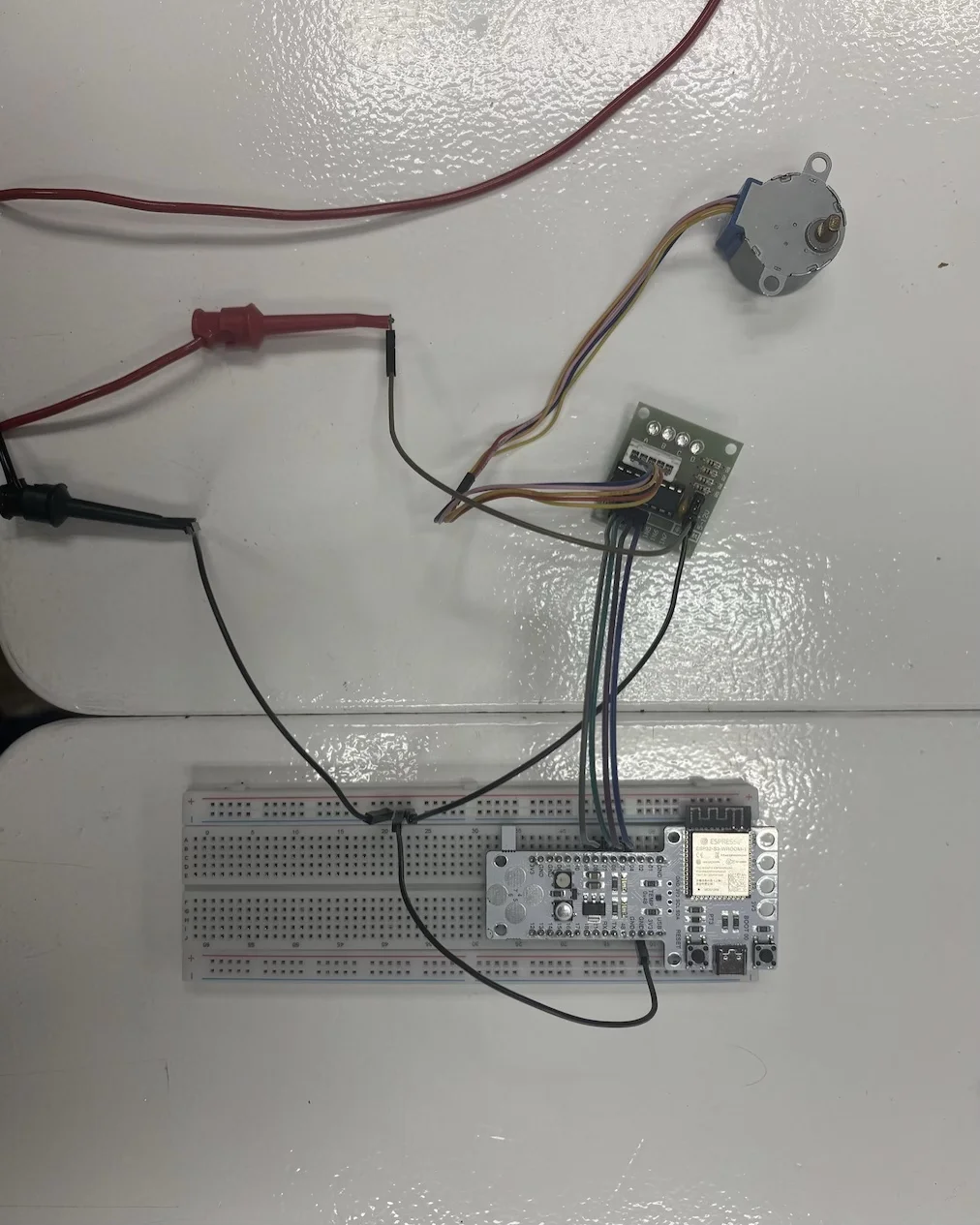
The stepper motor is connected directly to the ULN2003 driver through the provided connector, ensuring correct coil mapping and reducing wiring errors.
Barduino Wiring Detail:
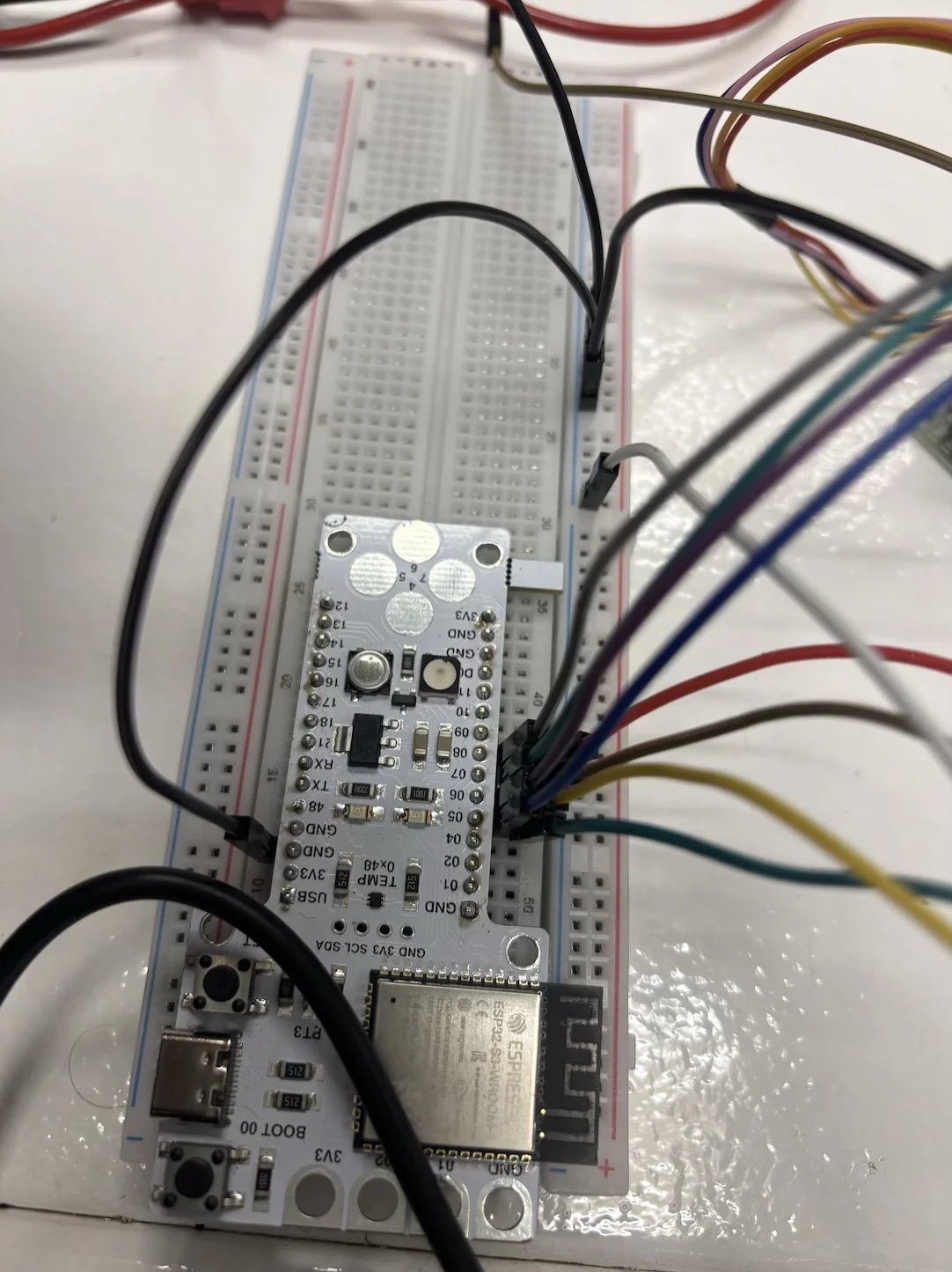
Close-up of the GPIO connections between the Barduino and the ULN2003 driver. This helps verify correct pin mapping and stable jumper connections.
Signal Communication:
Unlike more advanced drivers, this system does not use STEP/DIR signals.
Instead, the ULN2003 driver controls the motor by toggling combinations across 4 pins:
- N1
- N2
- N3
- N4
Each combination energizes different coils inside the stepper motor, producing rotation through a stepping sequence.
Power:
Although the stepper could technically run from the Barduino USB (5V), we used an external power supply to:
- Avoid noise affecting the microcontroller
- Prevent voltage drops
- Protect the board from current spikes
Pin Connections:
Driver to Barduino:
1N1------- PIN_05
1N2------- PIN_06
1N3------- PIN_07
1N4------- PIN_08
Power:
External Power Supply
- Set to 5V and 2A
Driver:
- VCC ----- External Power Supply
- GND ----- To Barduino ground via bus rail
Important:
All grounds must be shared (common ground between Barduino and logic analyzer).
CODE:
To move consistently in one direction:
#include <AccelStepper.h>

#define IN1 5
#define IN2 6
#define IN3 7
#define IN4 8

AccelStepper stepper(AccelStepper::HALF4WIRE, IN1, IN3, IN2, IN4);

void setup() {
  stepper.setMaxSpeed(2000);
  stepper.setSpeed(1000);
}

void loop() {
  stepper.runSpeed();
}
Logic Analyzer Group Work:
Working with the stepper/driver connection, we measured the signals across all 4 pins (5,6,7,8) to understand the stepping behavior.
Logic Analyzer Hardware:
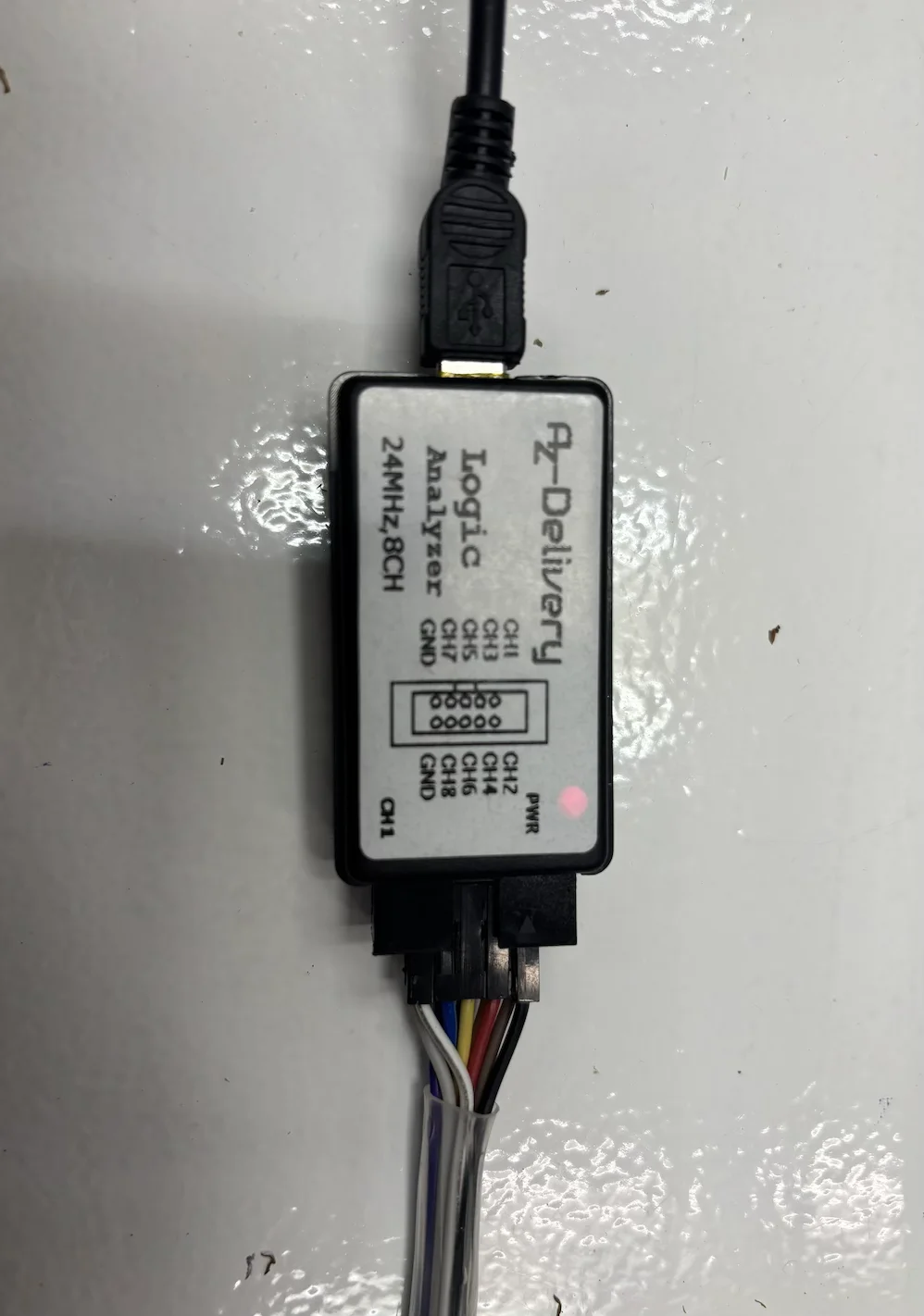
We used a generic 24MHz, 8-channel USB logic analyzer compatible with Saleae Logic 2.
Set up:
Connect Logic analyser:
- Connect the ground jumper (white) to the breadboard ground rail
- Ensure Barduino and logic analyzer share the same ground
Connect channels:
- CH1 → PIN_05
- CH2 → PIN_06
- CH3 → PIN_07
- CH4 → PIN_08
Probing Process:
During measurement:
- Probes were connected directly to GPIO pins
- Stable contact was maintained
- Wiring was adjusted to reduce signal noise
Saleae Logic 2
Download & run Saleae Logic 2
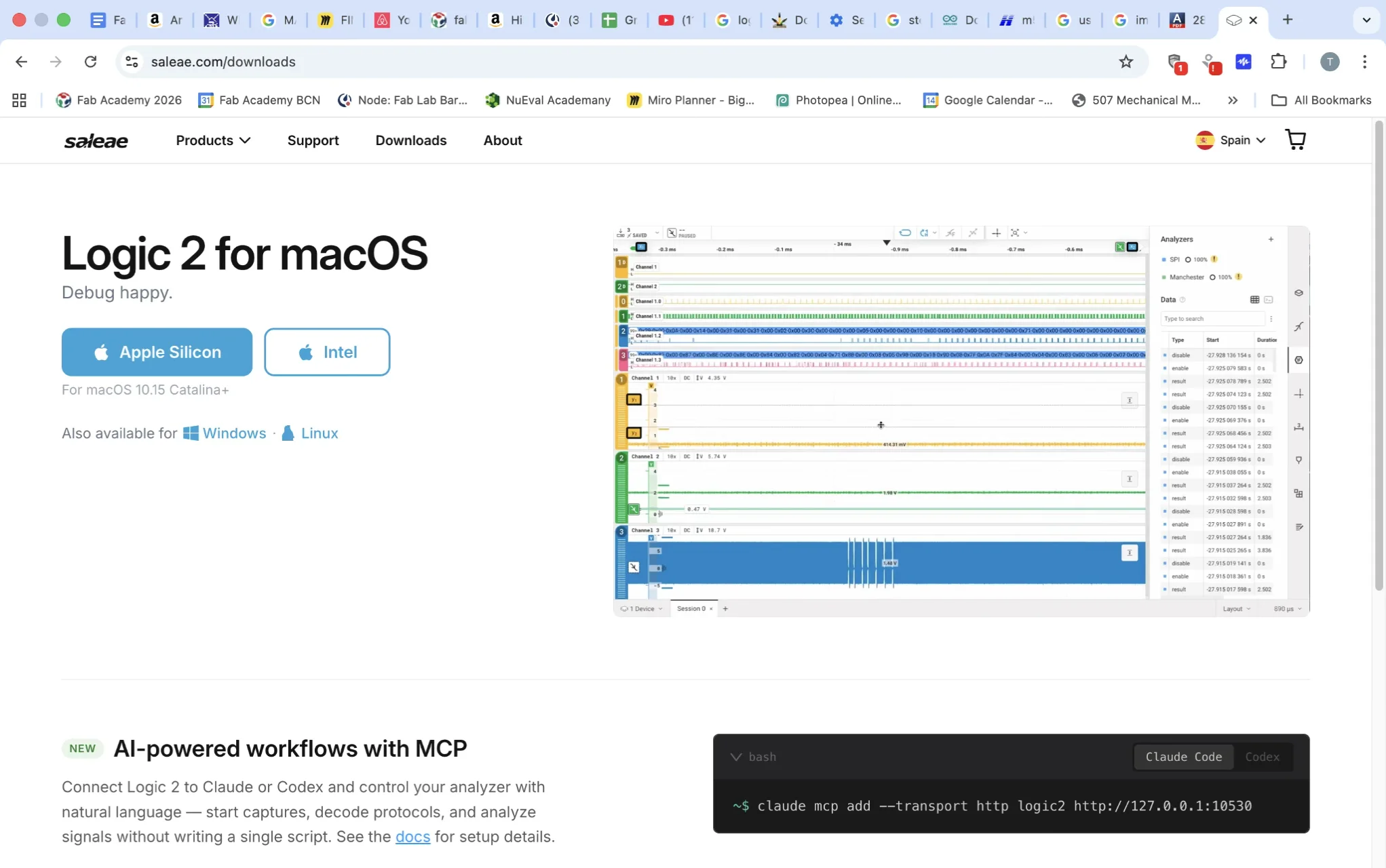
Choose Connect Logic MSO as software can work with a variety of analyzers.
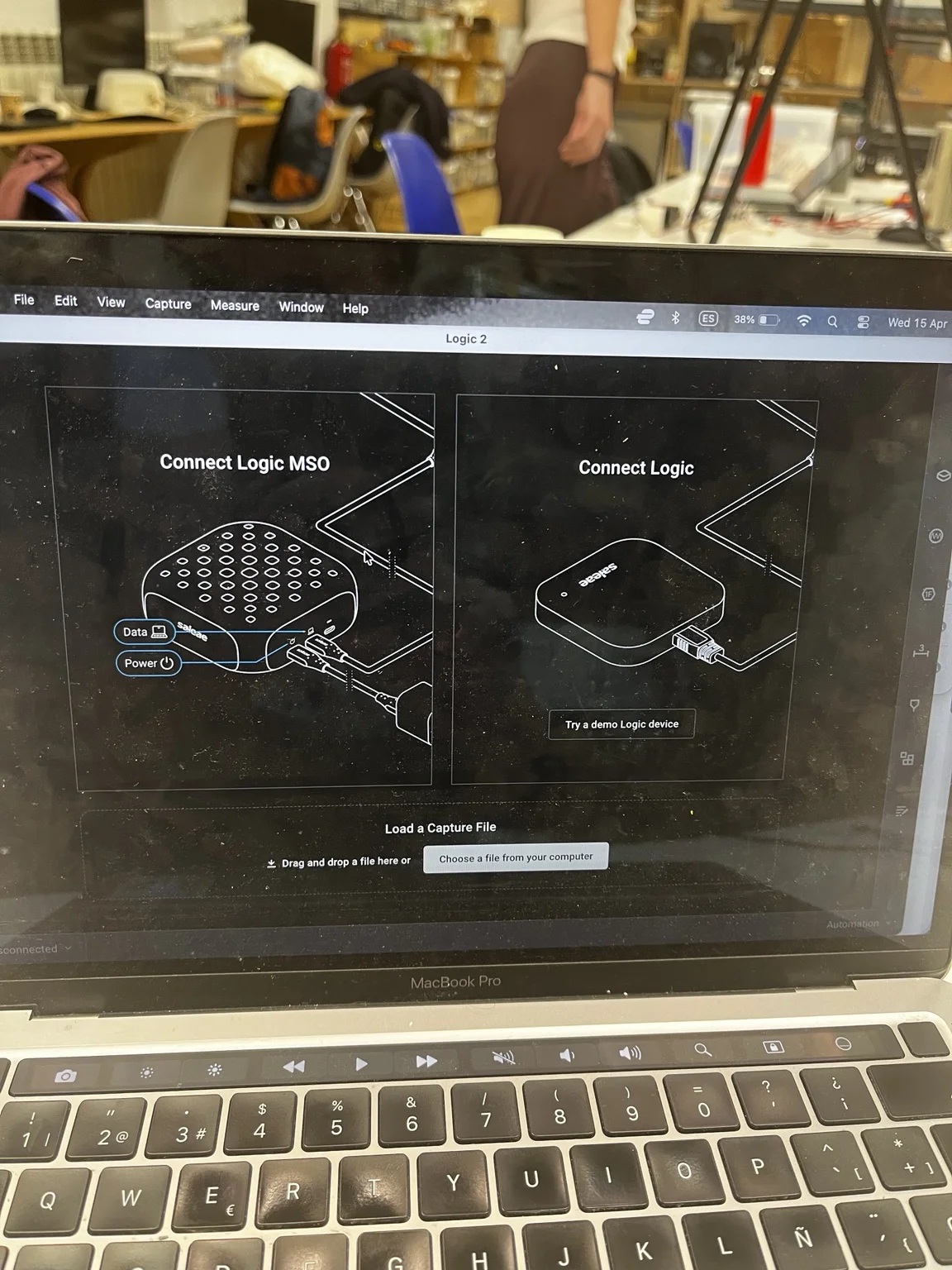
Configure settings:
- Connect logic analyser to USB
→ Status should show “connected”
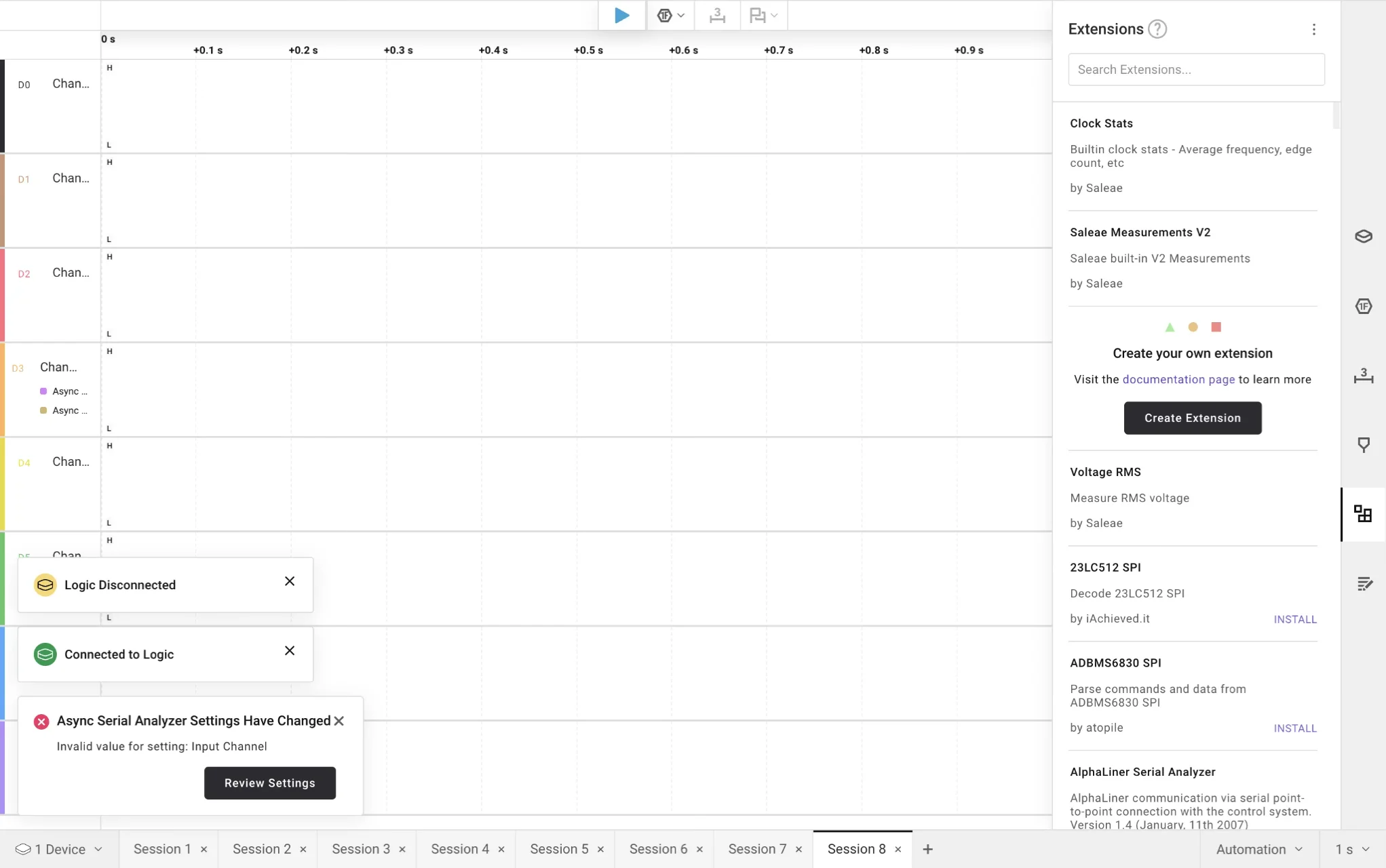
- Add analyser
Select:
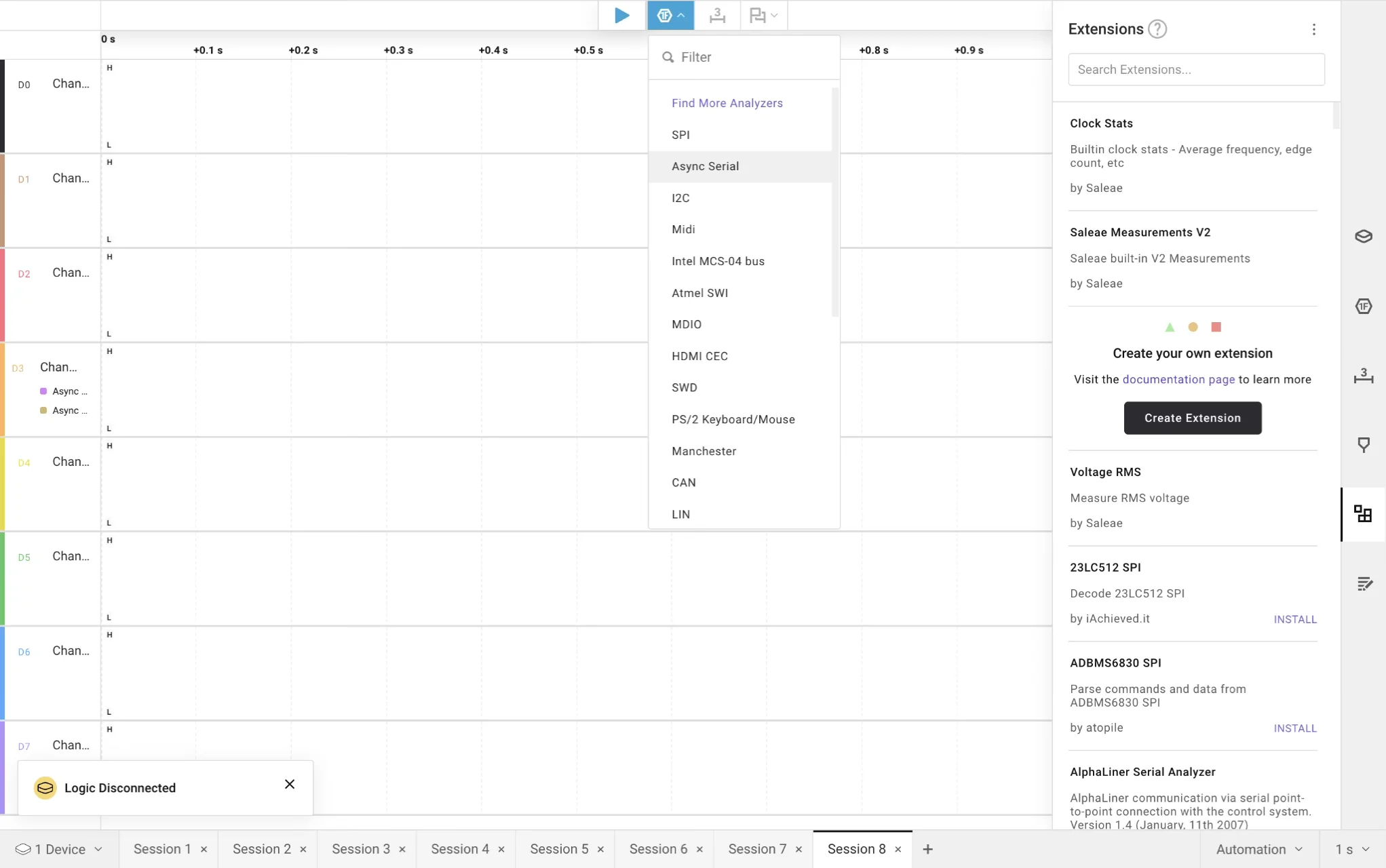
-
Async Serial
-
Configure:
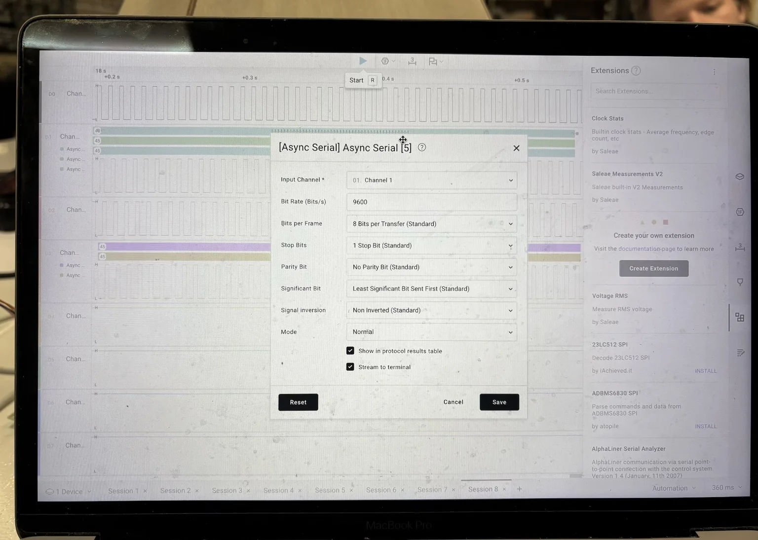
- Bit Rate: 9600
- Select correct input channel
- Disable unused channels
Signal Capture:
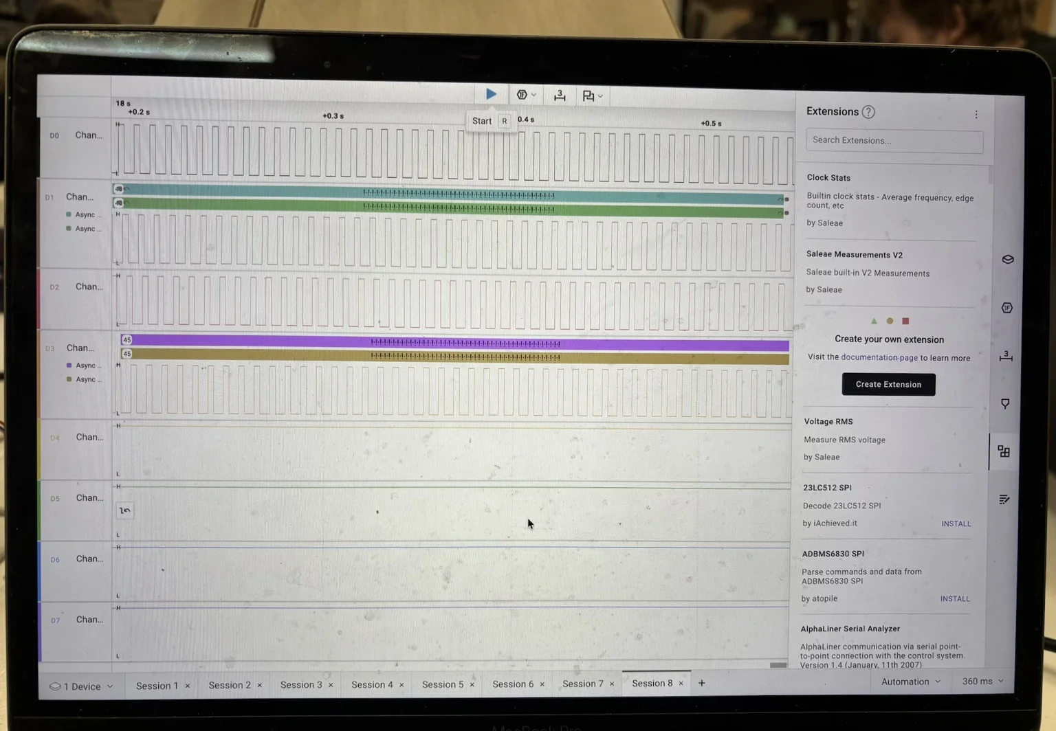
We observed:
- Square wave signals across all 4 channels
- Sequential activation pattern
- Repeating stepping cycle
Each channel corresponds to one coil activation signal, confirming the stepping sequence of the ULN2003 driver.
Signal Detail (Zoom):
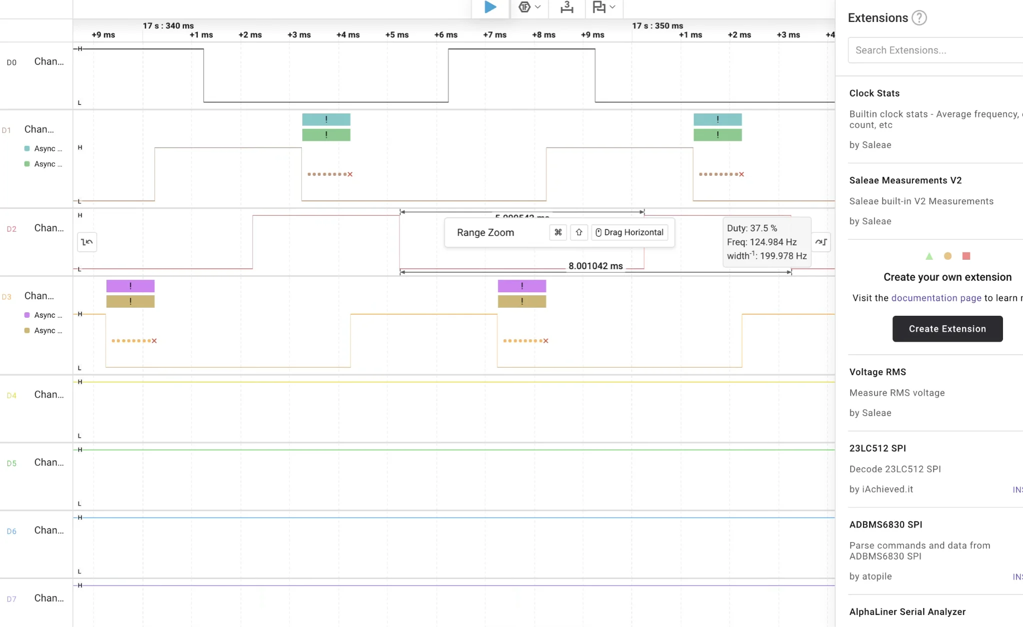
Zooming into the signal shows:
- Precise timing between pulses
- Non-overlapping activation pattern
- Clear phase shift between channels
Signal Capture (Video)
This video shows the real-time stepping sequence captured across the four control pins.
We can observe:
- The sequential activation of each channel
- The repeating stepping cycle
- The relationship between signal timing and motor movement
During testing, we also verified the signal mapping by disconnecting individual pins.
When a pin was removed, the corresponding channel signal disappeared, confirming correct channel-to-pin assignment and measurement reliability.
Test 1:
#include <AccelStepper.h>

#define IN1 5
#define IN2 6
#define IN3 7
#define IN4 8

AccelStepper stepper(AccelStepper::HALF4WIRE, IN1, IN3, IN2, IN4);

void setup() {
  stepper.setMaxSpeed(1000);
  stepper.setSpeed(800);
}

void loop() {
  stepper.runSpeed();
}
Observations from Measurement:
- Pins are activated sequentially, not simultaneously
- The pattern is cyclical and consistent
- Speed directly affects signal frequency
- ULN2003 converts digital signals into coil switching
Additional Notes:
- LED indicators helped correlate signals with physical motion
- Stable grounding was critical
- Logic analyzer made invisible signals understandable
Conclusion:
Through this test we were able to:
- Confirm the stepping sequence visually and digitally
- Understand multi-pin motor control
- Relate software commands to physical behavior
- Validate the logic analyzer as a debugging tool
- Observe pulses, waveforms, and numerical signal data generated by the code
By using the logic analyzer, we were able to translate the behavior of the code into visible electrical signals represented in software. This allowed us to see what is normally hidden — the timing, sequencing, and logic behind the motor control.
This made it possible to better understand how digital signals are structured and how they directly affect physical movement. It was especially useful to observe the relationship between code execution and real electrical behavior in real time.