Week 7 - Computer Controlled Machining
This week we learned and practiced Computer Controlled Machining on a CNC matchine (Computer Numerical Control).
Group assignment:
- Complete your lab's safety training
- Test runout, alignment, fixturing, speeds, feeds, materials and toolpaths for your machine
- Document your work to the group work page and reflect on your individual page what you learned
Computer Controlled Machining Process
-
Measure material
-
Design something BIG
-
CAM -> Gcode generation
-
Gcode is checked by someone
-
Design milled
-
Design assembled
-
Design finished
Summary of Lab Safety Training
Process
-
Measure
-
Design
-
RinoCAM setup
-
G-code checks
-
Milling
1. Measure
Measure your matrial and make sure that you have what you need.
2. Design
Using a 3D design software prpare a model with parts that you would like to cut on CNC. This tutorial provides a great guide for how to go about creating a design that will work well on a CNC matchine
3. RinoCAM
A good tutorial for RinoCAM can be found here
Steps for setting up your cuts in RinoCAM
1.Select Machine - 3 axis CNC_STEP_BCN
2.Box Stock:
- Stock Geometry: origin in the top left buttom corner
- Corner coordinates: 0, 0, 0
- Dimensions: L, W, H
3.Screw material and then around the area you want to cut
4.Draw points in Rhino where you have located your screws
5.Go to Machining operations - 2 axis
- Roughing
- Pocketing (emptying part of the material)
- Engraving (on cut) (choose it for making the "screws" spot and then select the points where you want to make the mark)
6.Create/Select Tool
7.Fablab just have bold and flat mills.
-
For the screws choose flat (next parameters should be according to the one you are going to use)
-
Name it (this is an example of mill bit values, you have to choose your own)
- Holder Dia: 30
- Holder Len: 45
- Shank Dia: 6
- Tool Len: 105
- Shoulder Len: 60
- Flute Len: 45
- Tool Dia: 6
- Flute: 1
- Spindle Parameters:
- Speed: 18000 RPM,
- Direction: CW,
- Cut (calculate with cheapload equation): 4500,
- Retract: same as Cut,
- Departure: same as Cut.
- Plunge ("half of cut"): 2000,
- Approach: same as plunge and Engage: same as plunge.
- Clearance Plane: Clearance Plane Definition: Part Max Z + Dist: 20 (Never Automatic)
- Cut Parameters: we only care about "Cut Depth Control": 3mm
- Entry/Exit:
- Sorting: Minimum Distance Sort
-
For pocketing:
- Feeds and Speeds: 18000 RPM
- Clearance Plane: Clearance Plane Definition: Part Max Z + Dist: 20 (Never Automatic)
- Global Parameters: Climb
- Cut Patter: Offset
- Do everything else!!!!!
For profiling/outside: use along path! when using profiling the machine doesn't recognize other pieces. So we'd like to use along path so it can slide and approach directly to the selected piece. Remember to add taps (bridges).
G-code Checks
Visually inspect your simulated toolpaths after selecting cutting parameters. Have an instructor review.
Milling
If the precious steps are commpleted correctly, this is where you sit back and watch the machine do the work. Load each tool path file to the matchine and execute in order.
- Cuts for fixturing
- Engraving and surface cuts
- Through cuts
- Final cuts to separate the piece from the stock material
As each cut is made, make sure to pay attention to changes in quality, listen for chatter from the bit or other sounds that could indicate that settings are not correct. You may need to adjust settings as you go.
Conclusions
Post processing is often required. You will need to use a chisle to remove the bridges that hold the final peice to the staock marterial. Often sanding or other post processing is required.
Testing CNC Parameters
The objective of this test was to beter understand the performance of the CNC Machine and the quality of the cut We tested the following parameters:
-
Runout – The amount by which a rotating cutting tool deviates from perfect concentric rotation, causing the effective cut width to differ from the tool's nominal diameter.
-
Alignment – The process of ensuring the machine, workpiece, and cutting tool are positioned and oriented correctly relative to one another.
-
Fixturing – The method of securely holding and locating a workpiece during machining to prevent movement and maintain accuracy.
-
Speeds – The rotational speed of the cutting tool, typically measured in revolutions per minute (RPM).
-
Feeds – The rate at which the cutting tool moves through the material, typically measured in units of distance per minute.
-
Materials – The workpiece substances being machined, whose properties influence tool selection, cutting parameters, and machining strategy.
-
Toolpaths – The programmed routes and movements that a CNC machine follows to remove material and create the desired geometry.
Test Design
To practice we chose a basic design that would allow us to easily test these parameters. The design included: screw holes for fixturing, multiple tool paths for testing runout, alignment, and speed.
Test Model
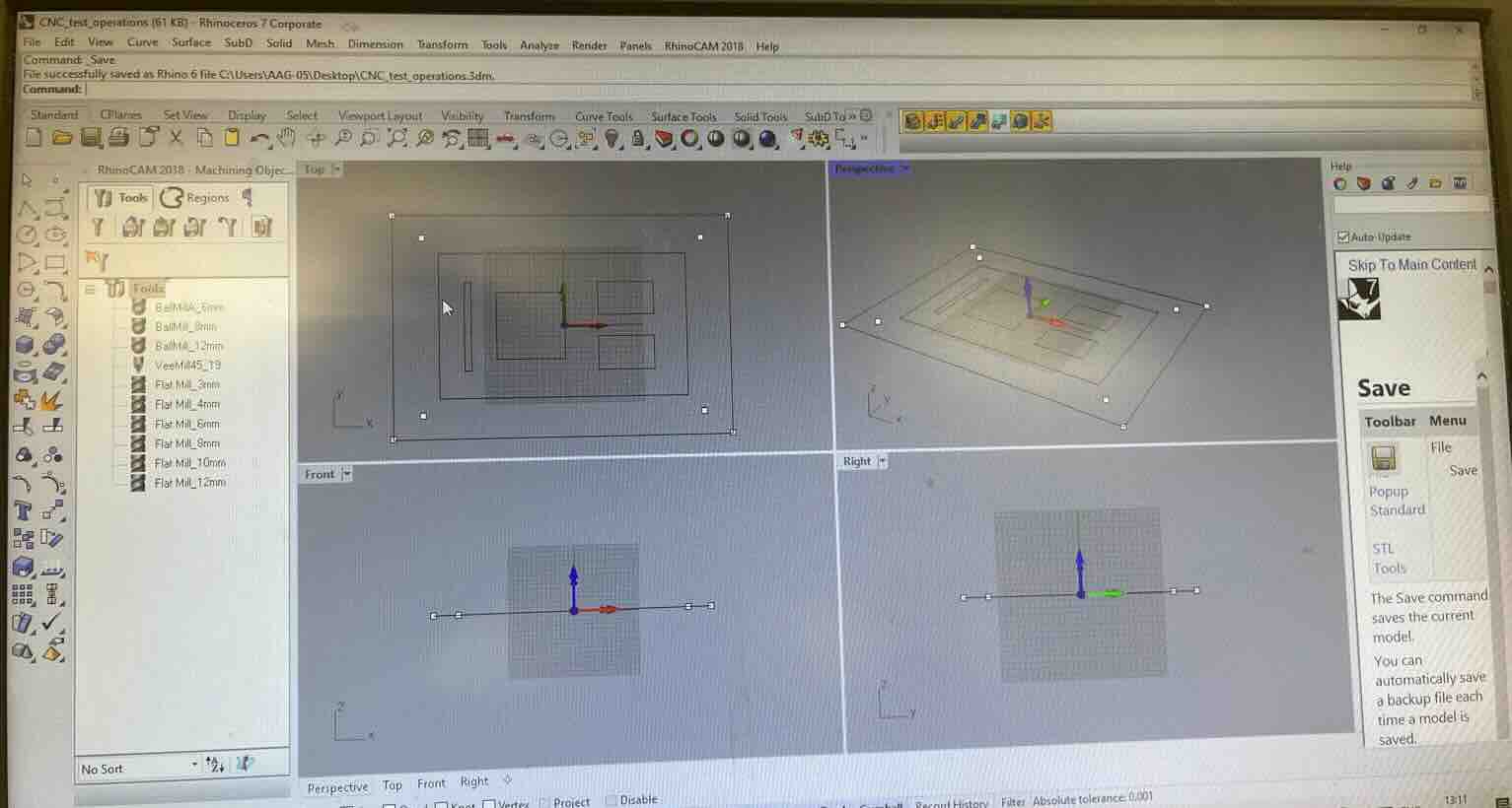
Setup
- Save design:
After creating the design in Rhino save it to a zip drive and open it on the CNC conputer. Open the desired file in Rhino, make sure all tool paths are joined and delete all unnessesary lines. Place the desired material on the table and set the Machine Coordinates System (MCS) by moving the bit to the corner of the material.
- Set Z zero:
Touch the tip of the bit to the material and clicking the Z-zero button.
- Select the cutting tool:
Choose the appropriate end mill, ball mill, V-bit, or other cutter and define its dimensions in the tool library.
- Create machining operations:
Select toolpaths such as facing, profiling, pocketing, drilling, roughing, or finishing based on the features being machined.
Slot cutpath
For a slot the width of the bit, the cut path should be drawn as a single line
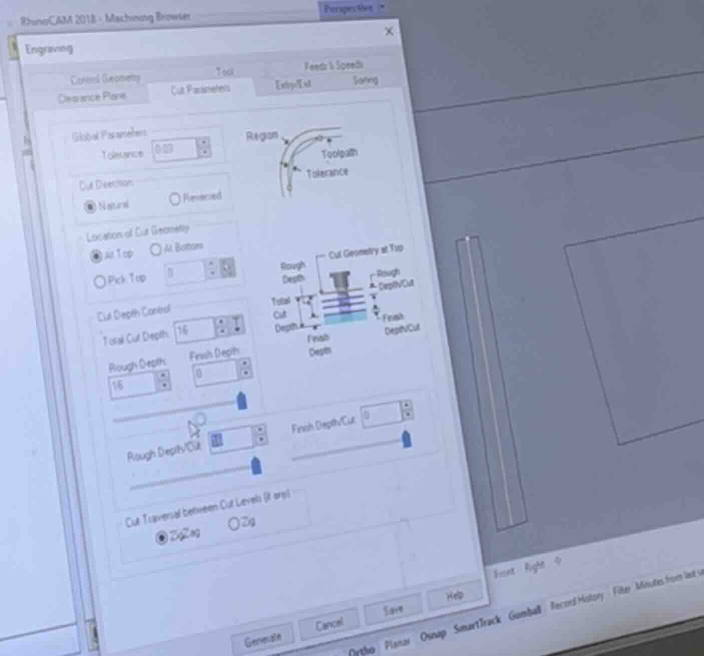
- Configure cutting parameters – Set spindle speed, feed rate, plunge rate, step-over, step-down, machining tolerances, and cutting direction. Parameters can be adjusted via several windows. Speed and others are shown in the image above while stepover is shown below.
When cutting a flat surface, the toolpath should overlap to ensure all material is removed cleanly. The amount that each path overlaps should be specified.
Stepover distance
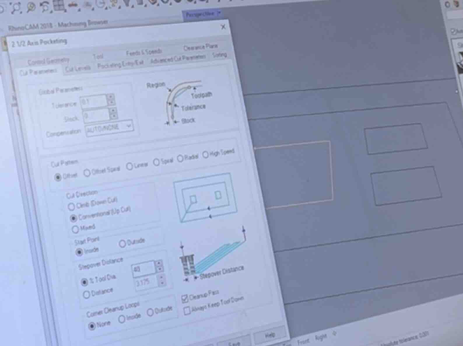
- Generate the toolpaths – Calculate the cutter movements based on the selected operation, tool, and machining parameters.
This is may be done automatically after selecting parameters. it is important to click on each tool path are review the simulated path to make sure it represents your intent
Final cut toolpath
- Set up the CNC machine and run the job – Secure the stock, install the tool, set the work zero, and execute the generated G-code.
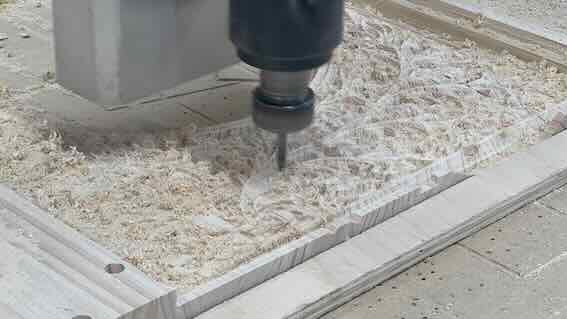
Cutting
Assessment
Before post-processing
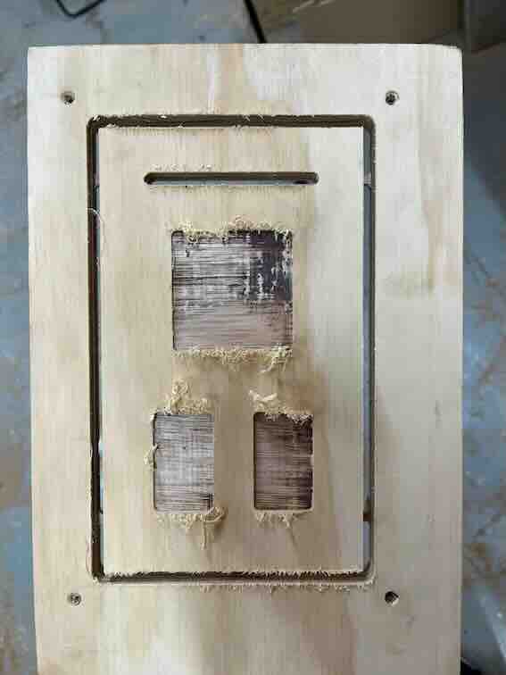
As you can see from this image the up-cut bit used caused a significant amount of wood fiber to stay attached to the edge of each cut. This can be easily cleanned up with sand paper.
Runnout
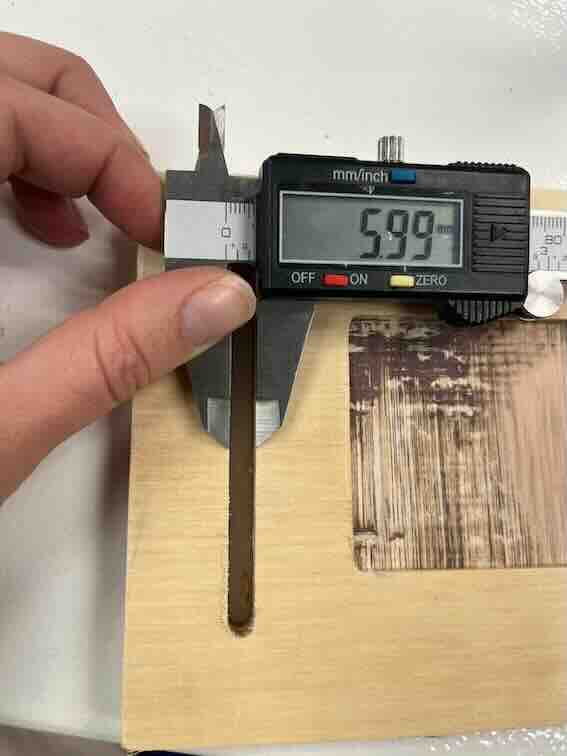
In this case, there was no runnout. You can see this in the measurement of the bit width slot. The width of the slot was exactly the width of the bit used - 6mm
Alignment
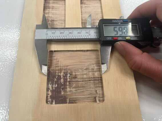
This image show that the machine is well alligned. In both the x and the y dimension the final product is exactly the length specified in the design.
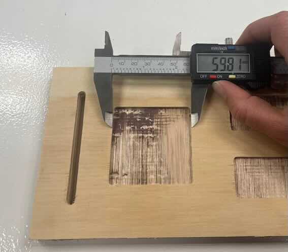
Speed
The two smaller pockets in the design were cut using two very different speeds and RPMs. As you can see from the final product below, the speed did not significantly effect the quality of the cut
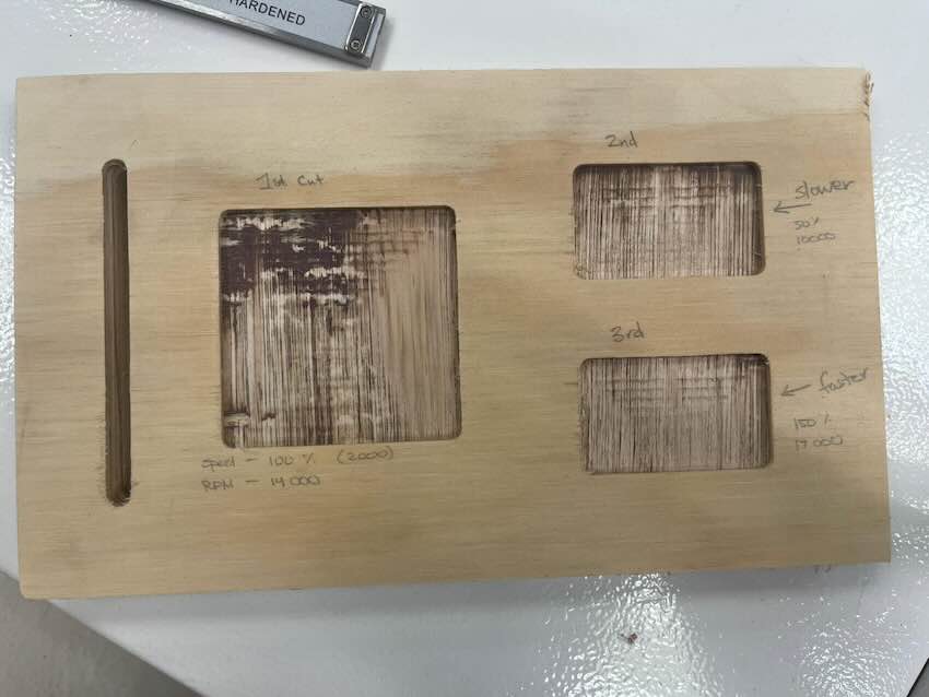
Material
In addition to the plywood test shown above we experimented with milling solid pine. The settings for this cut started as slightly slower than the plywood cut settings but were sped up half way through becuase the pine was very soft. Speed was also reduced for the finishing cut.
A Ball 4 mm bit was used to create a more consistent surface.