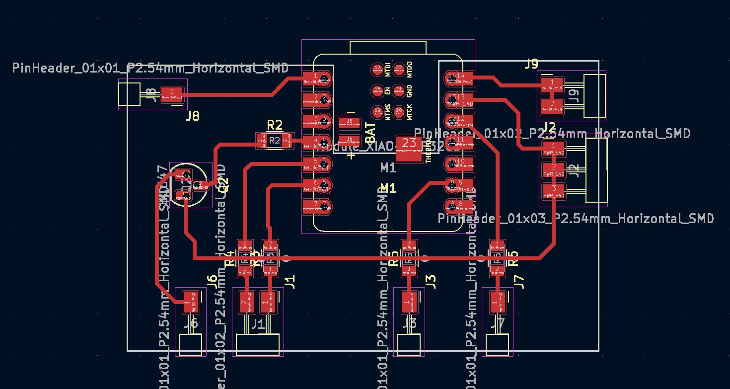
This is my working board. We require an NPN transistor because the active buzzer sometimes does not get enough current from the Xiao. The NPN transistor helps to amplify the current. Please don't be like me -- always make sure your throughholes let you put the transistor in from the back.
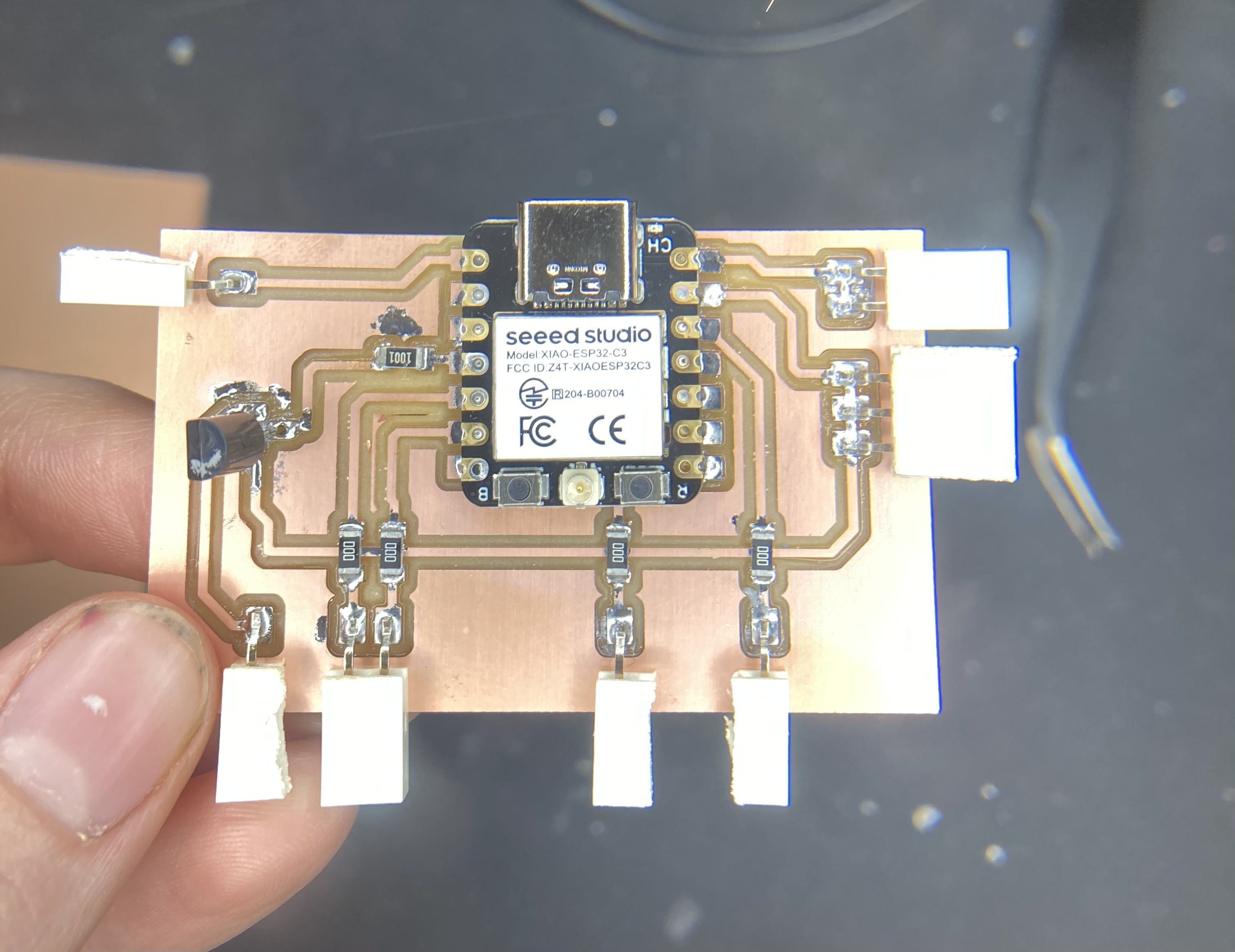
We only need a few pins for this project, 4 of which are taken by the rtc module. 3 are taken by the mq2, including A0. The buzzer needs 2 pins -- transistor pin E for the negative end and 5V for the positive end.
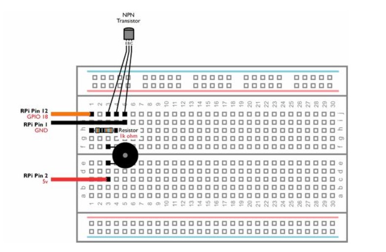
This diagram depicts how I had the buzzer on the breadboard. I used the same logic to connect each trace to each part. It was a little bit tricky logically.
The board with all of its components attached in their correct headers, and each part has its dedicated place. This board works the same as the breadboard in my final presentation, I tested it.
-min.jpg)
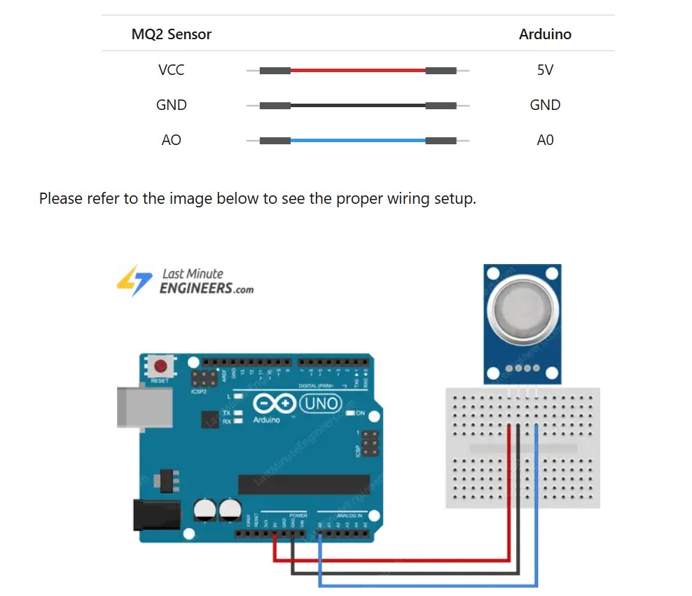
The mq2 needs a 5v, gnd, and an analog output pin for my application.
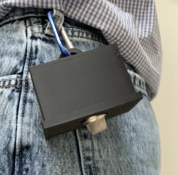
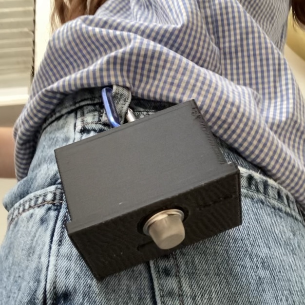
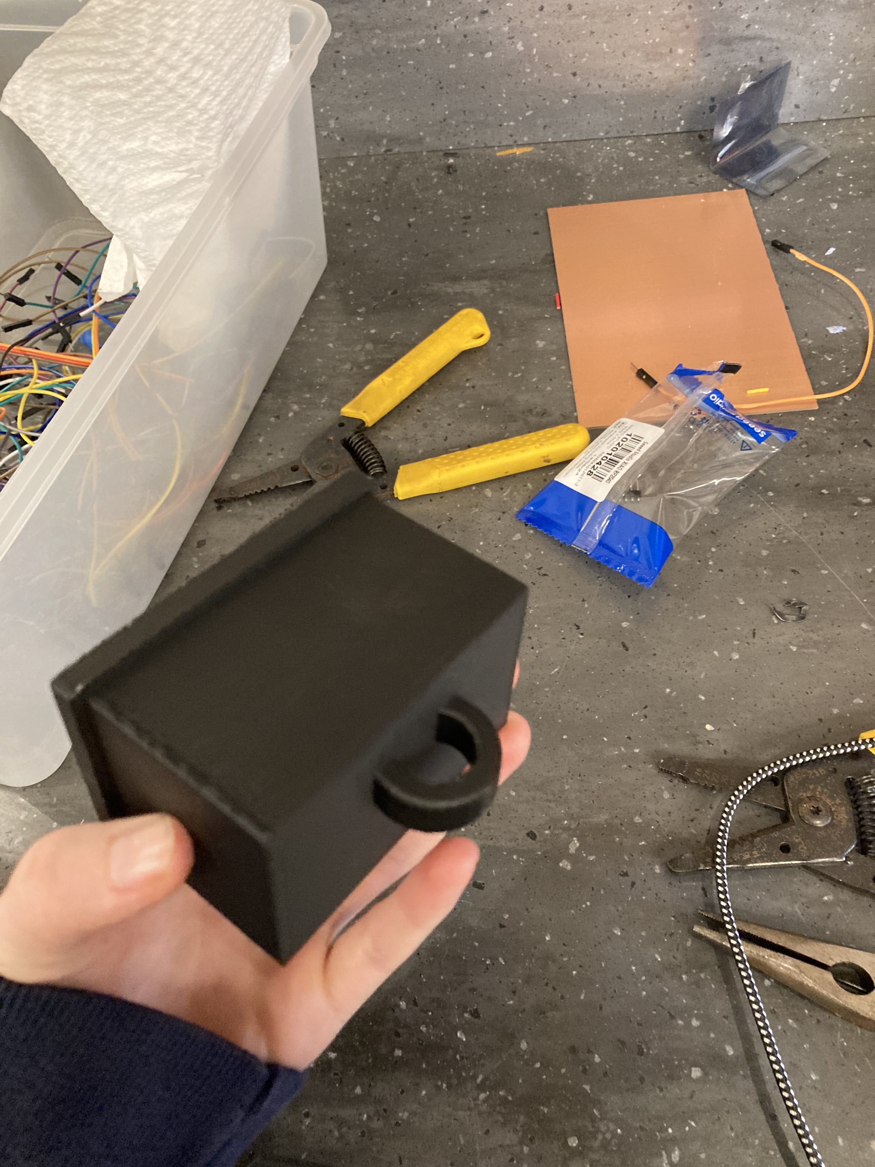
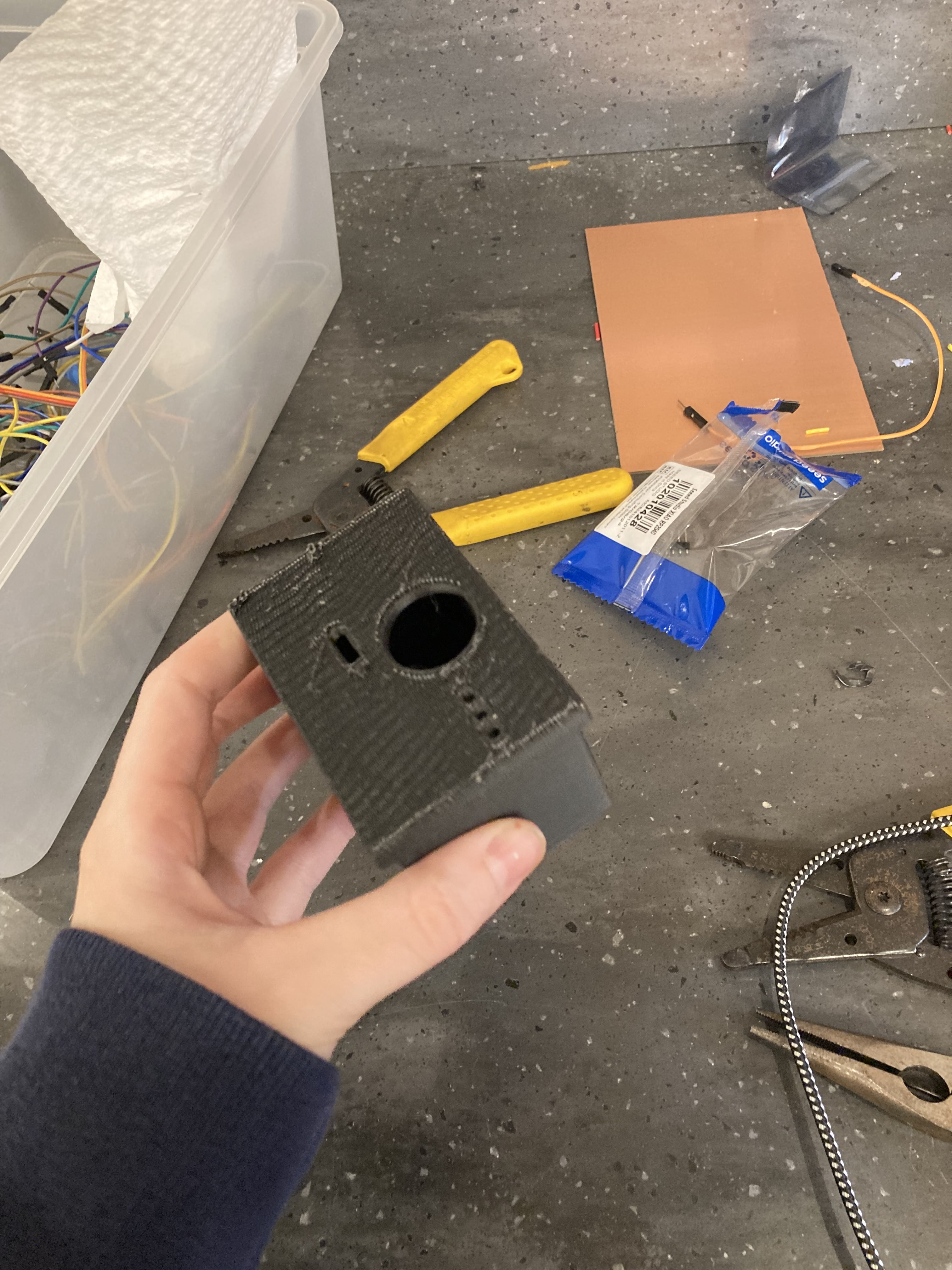
This is the print, based on the design above. Natural supports were generated inside the box, I removed them all. These pictures don't really show it, but there is a slot for the PCB. These also successfully printed, and I'll talk about the fact that the PCB is successfully held below. The large circle fits the MQ2 sensor so it can poke out to effectively detect environmental gas. There are speaker holes for the buzzer. There is also a USB-C cable slot. The circle thing at the bottom is for attaching a carabiner to, in order to attach to a belt loop or other piece of clothing, or keys/equipment. You'll see this demonstrated below.
The video below shows the PCB successfully mounted using the slots. I am trying to move it, but it won't budge, because it fits into the slot.
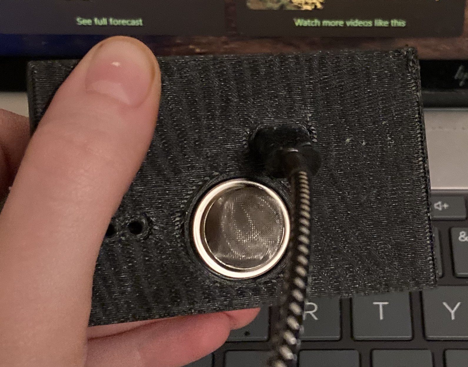
The MQ2 and USB-C fittings. For now, I will not solder a battery, so I definitely need the USB-C port. If there was a battery, the USB-C would be used to recharge the battery.
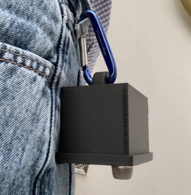
Demonstration of the 3D print with the carabiner attachment on a belt loop. You could also potentially put it on keys, clothing with loops and pockets, or equipment. The functionality of the actual board while in the box will be on the final project page and Applications and Implications, Project Development.