
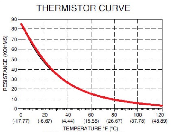
One of the input devices we tested was a thermistor. In the serial monitor, we can see that the analog output is around the 700 range. This represents the voltage divided by the reference voltage from the microcontroller. As the temperature decreases, thermistor resistance increases.
-min.jpg)
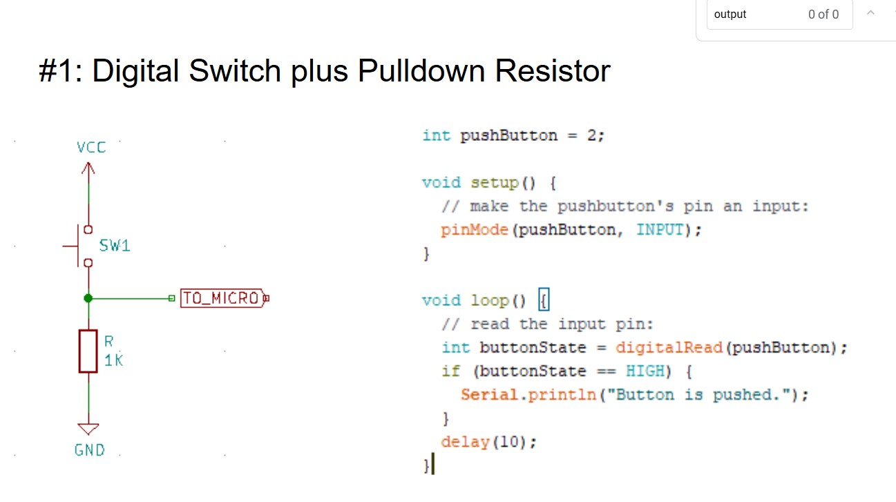
Below is a basic example of doing a digital read on an input device. The int stored from the digitalRead represents voltage. A voltage of less than 2.5V is LOW, while a voltage of 2.5V or higher is HIGH.
          #include

            // Define Keypad Rows and Columns
            const byte ROWS = 4;
            const byte COLS = 4;

            // This should match your actual keypad layout
            char keys[ROWS][COLS] = {
              { '1', '2', '3', 'A' },
              { '4', '5', '6', 'B' },
              { '7', '8', '9', 'C' },
              { '*', '0', '#', 'D' }
            };


            // Change these to match your actual ESP32 GPIO connections
            byte colPins[COLS] = {21, 4, 3, 2};  // GPIOs connected to keypad columns
            byte rowPins[ROWS] = {20, 8, 9, 10};  // GPIOs connected to keypad rows
            Keypad customKeypad = Keypad(makeKeymap(keys), rowPins, colPins, ROWS, COLS);

            void setup(){
              Serial.begin(9600);
            }

            void loop(){
              char customKey = customKeypad.getKey();

              if (customKey){
                Serial.println(customKey);
              }
            }
I made this circuit board with the keypad attachment from my earlier embedded programming assigment in mind. But this time, I'm making the keypad attach to a much smaller microcontroller (xiao esp32 c3). The keypad requires 8 digital pins. This requires at least 8 pin sockets.
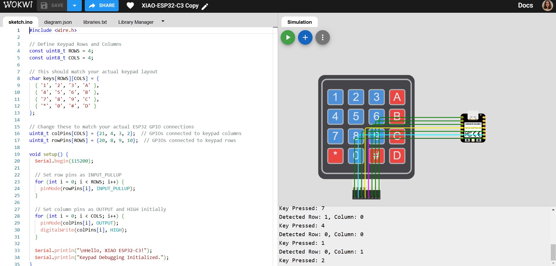
First, I took a look at this pinout diagram for the xiao. I needed 8 digital pins for input, and 3 pins for output. I chose the SDA and SCL (D4&D5) pins along with a random leftover digital pin (D3) for output. I need the SDA and SDL pins for an OLED display later.

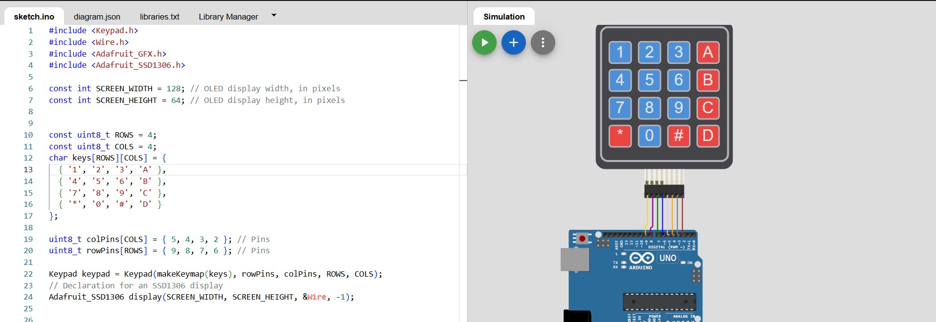
To be totally transparent, I decided on the pins I was going to use before I started coding, because the pins are pretty arbitrary for the keypad as long as they're digital. However, below is my code and diagram of What I pictured in my mind when choosing the pins. This is the link to my code and diagram.

My PCB and schematic. 0 ohm resistors were extremely important in this design. For their versatility, I used 10 kOhm resistors everywhere else.


I encountered a host of issues when cutting my circuit board. Namely, the tip kept breaking off the drill. To stop this, I put the cuff lower and set the Z axis in the middle, where my cut was having issues. We also lowered the speed by a lot in mod -- down to 6 mm/s.
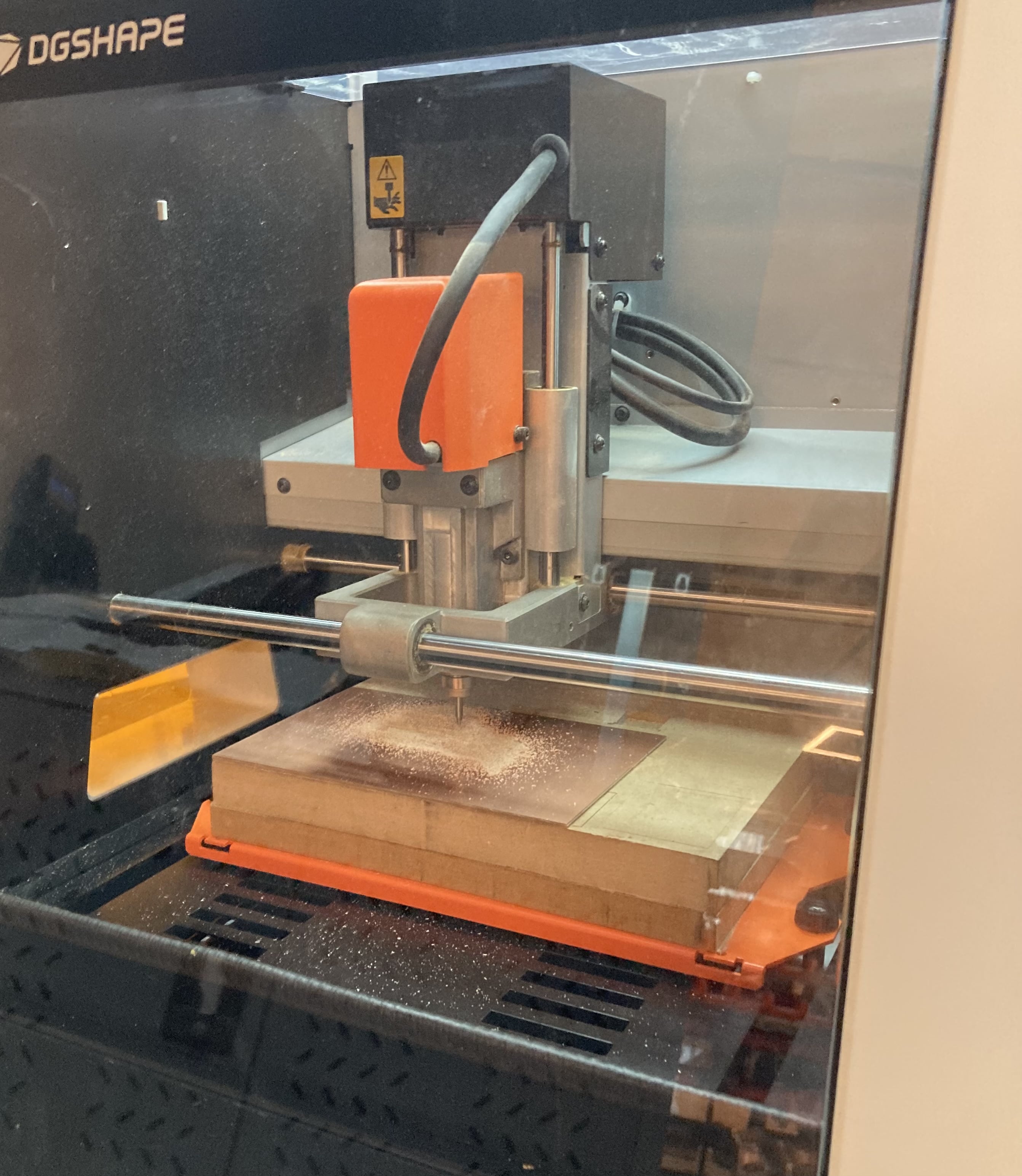
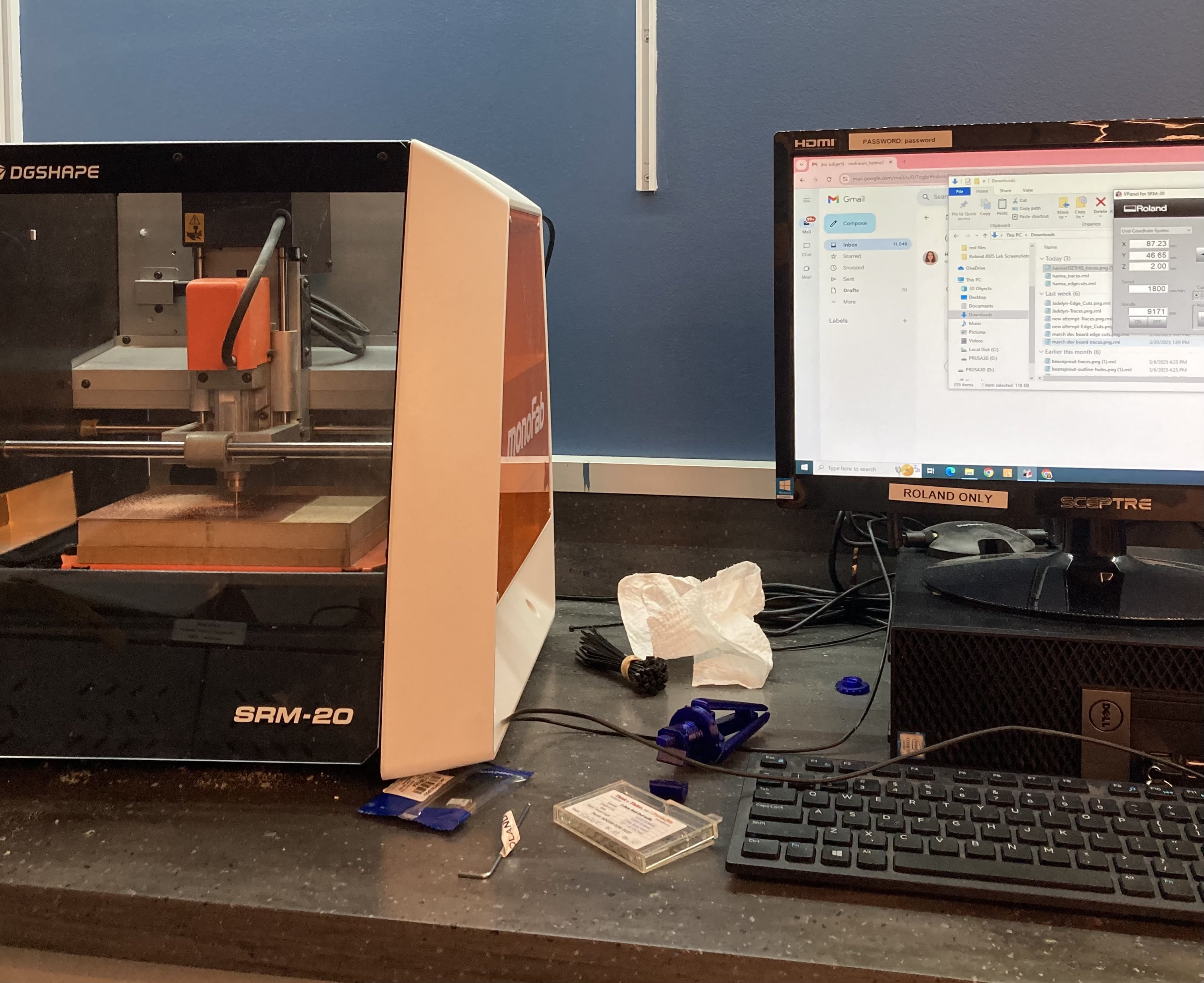
After these fixes, I didn't encounter any other problems. However, I did download the edge cuts too fast after I downloaded the traces from mods, which resulted in me basically re-downloading traces under the name edge cuts. The speed is 1800 mm/min on VPanel.
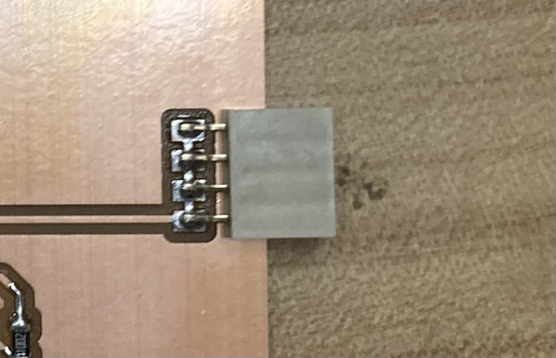
The quality of my soldering. I used tin paste and heat for the resisors, which I found way easier than the pen.
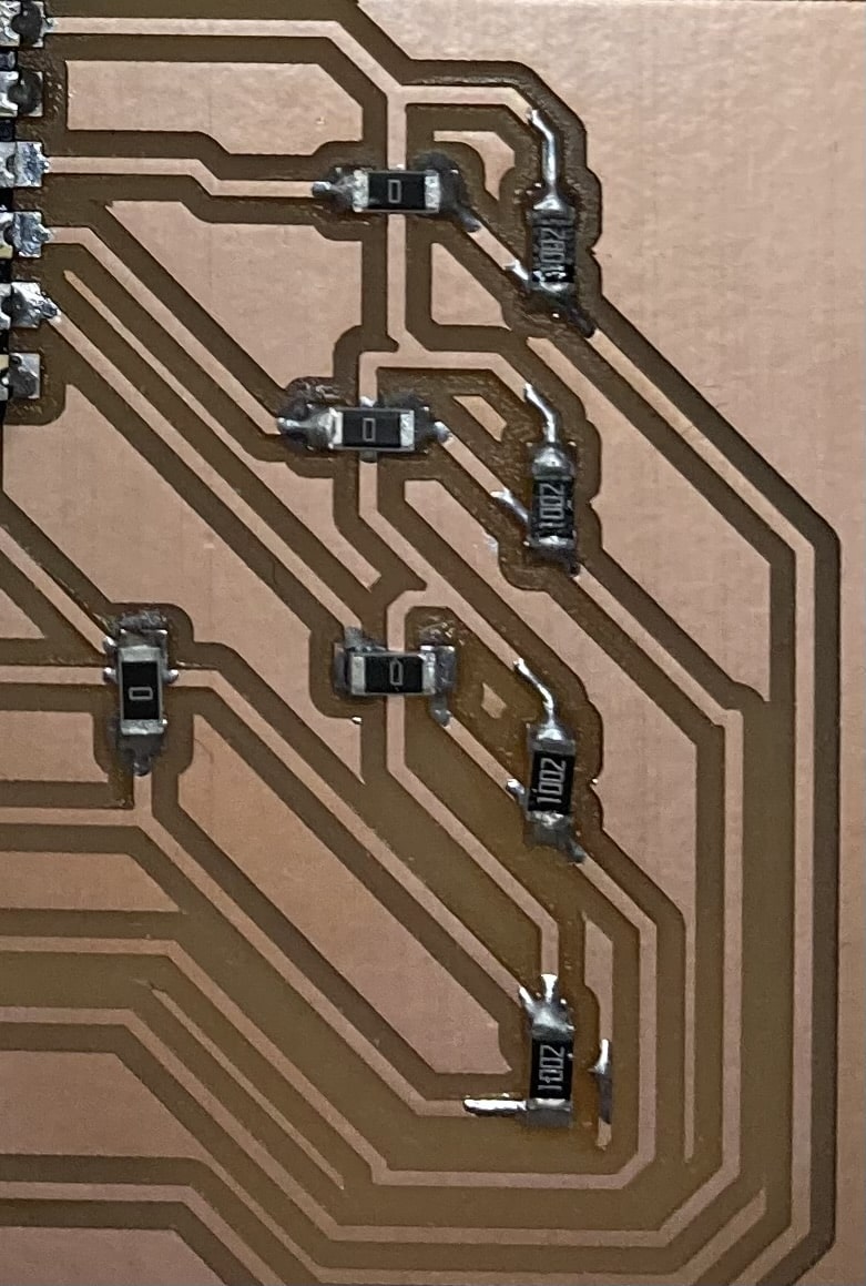
However, I would learn to not use the paste and heat for the microcontroller. I was having a lot of trouble trying to use the pen for the microcontroller, so I thought it would be better to use the paste and heat. THIS IS A VERY BAD IDEA!!!!!!!!!!!
-min.jpg)
The finished circuit board. Overall, great design, other than the microcontroller mishap.
-min.jpg)
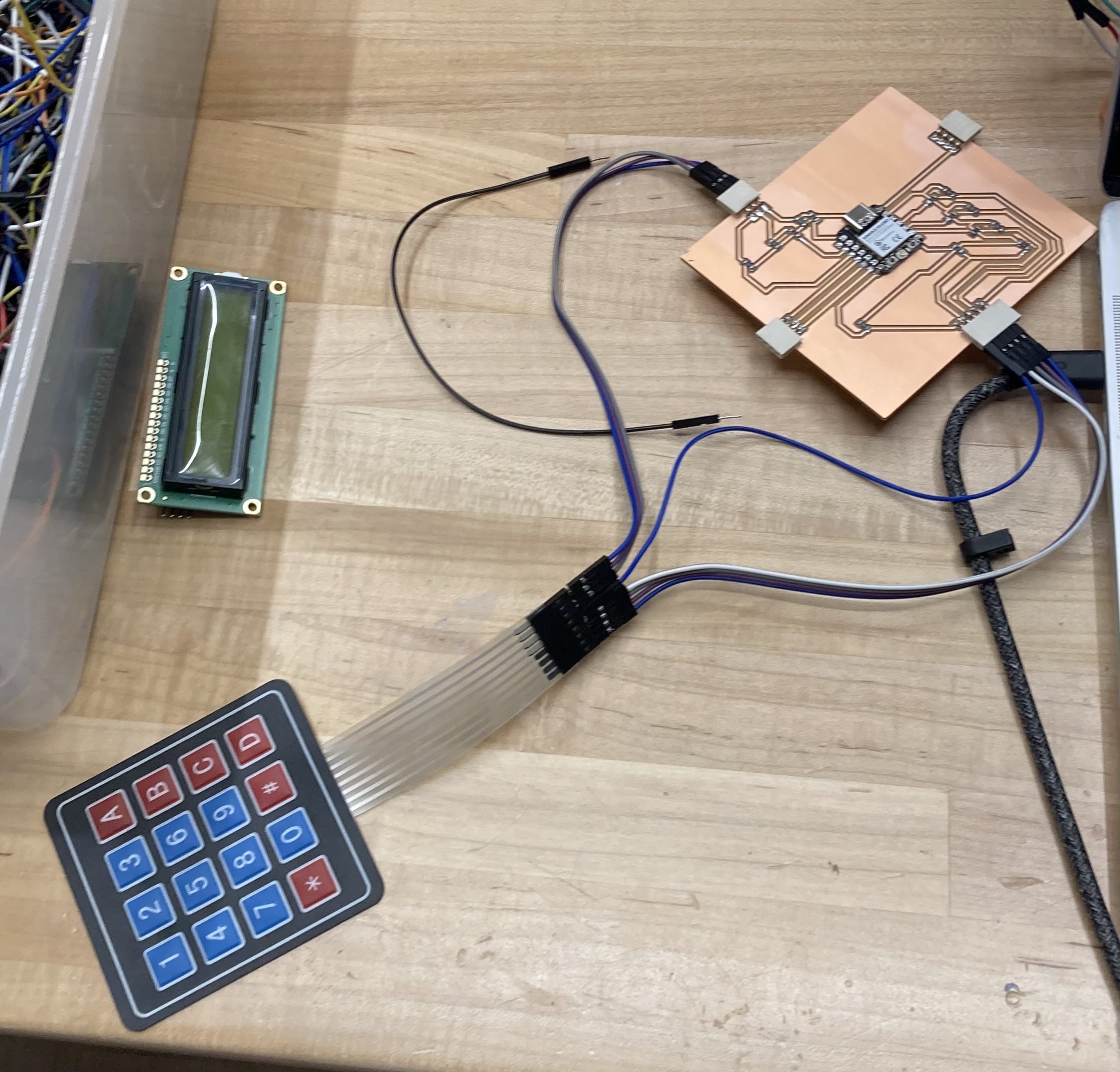
The microcontroller wiring. It uses the exact same pins as shown in the wowki esp32 code and diagram. The only difference is that we obviously have to use the pin sockets for connecting the jumpers. We can upload this code with this wiring and it would run perfectly fine.

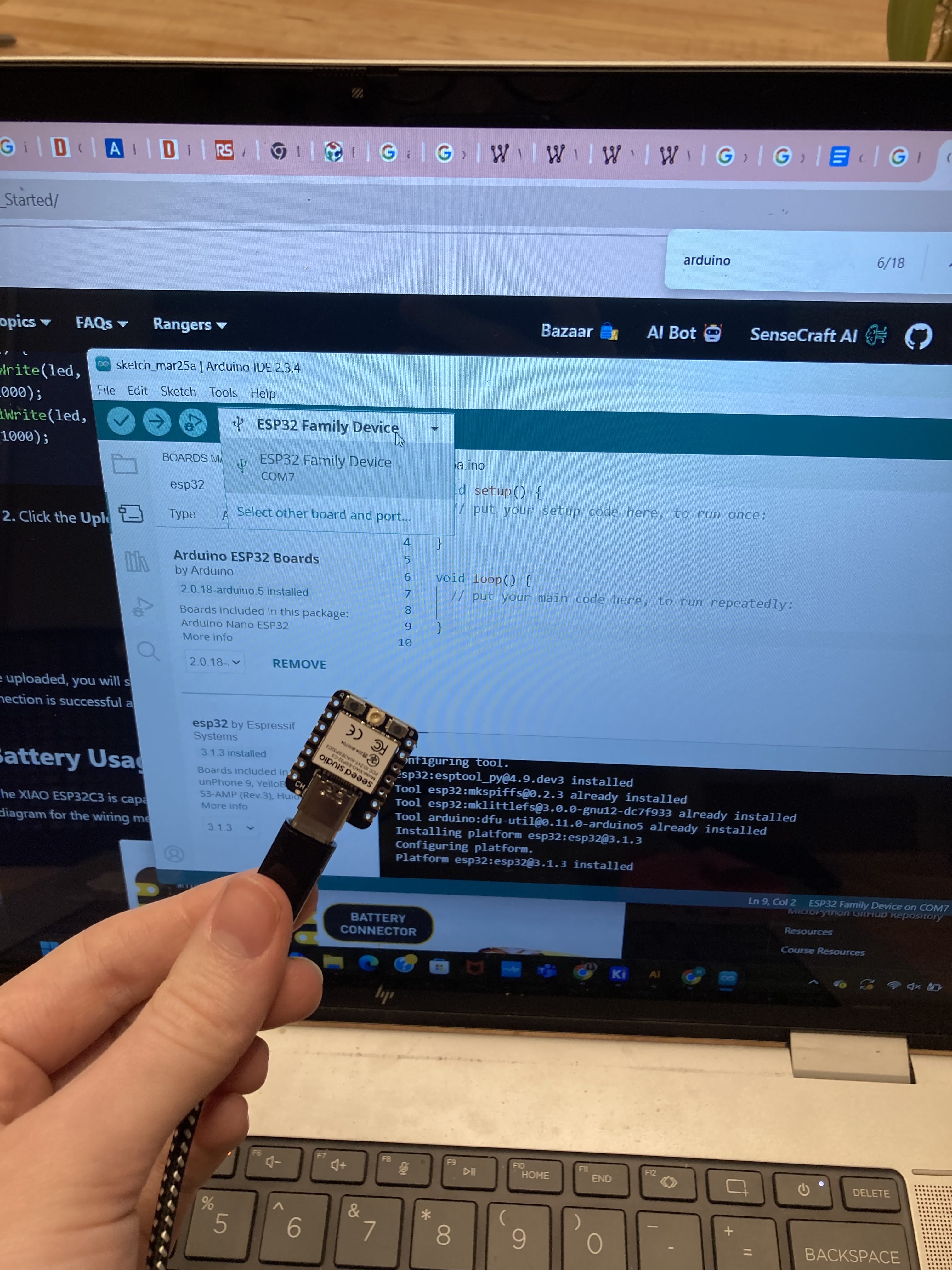
To use the ESP32 with the arduino IDE, we have to do some preparatory steps. Follow the steps on this webpage, scrolling specifically to the section below:
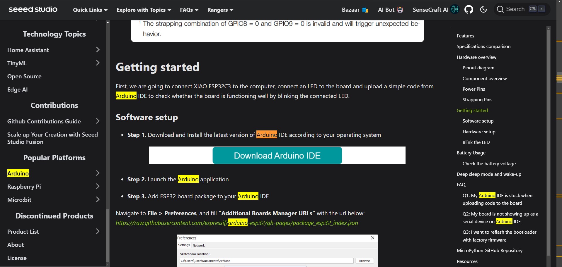
Use a microUSB cable to attach the esp32 to a device.
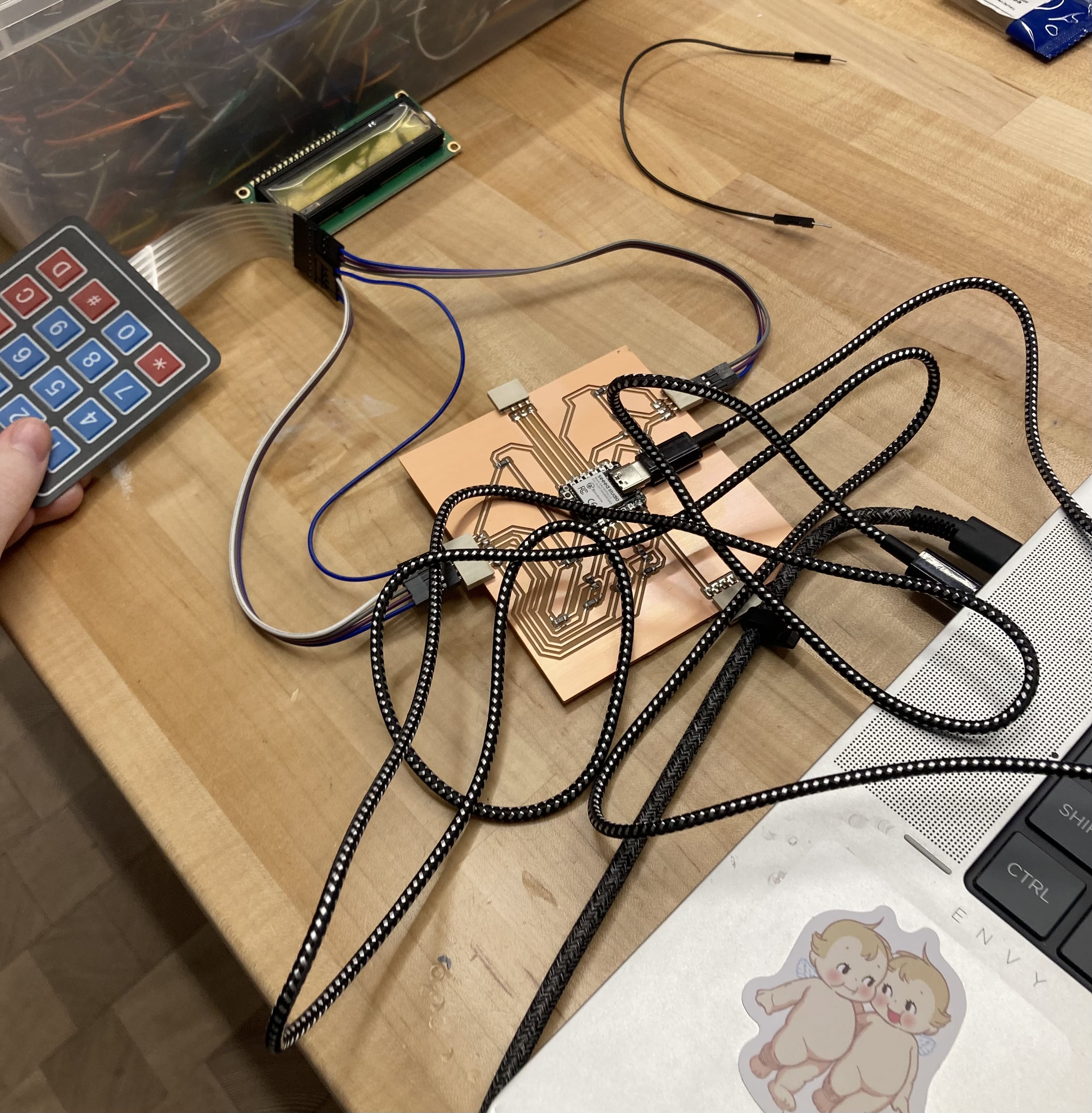
However, when I went to plug in my microcontroller on my board, I noticed that it wouldn't recognize it. When I tried again with another fresh xiao, it recognized the port. I believe it is pretty likely that I made the microcontroller melt too much by using the hot air pen. It may have also been nonfunctional previously.
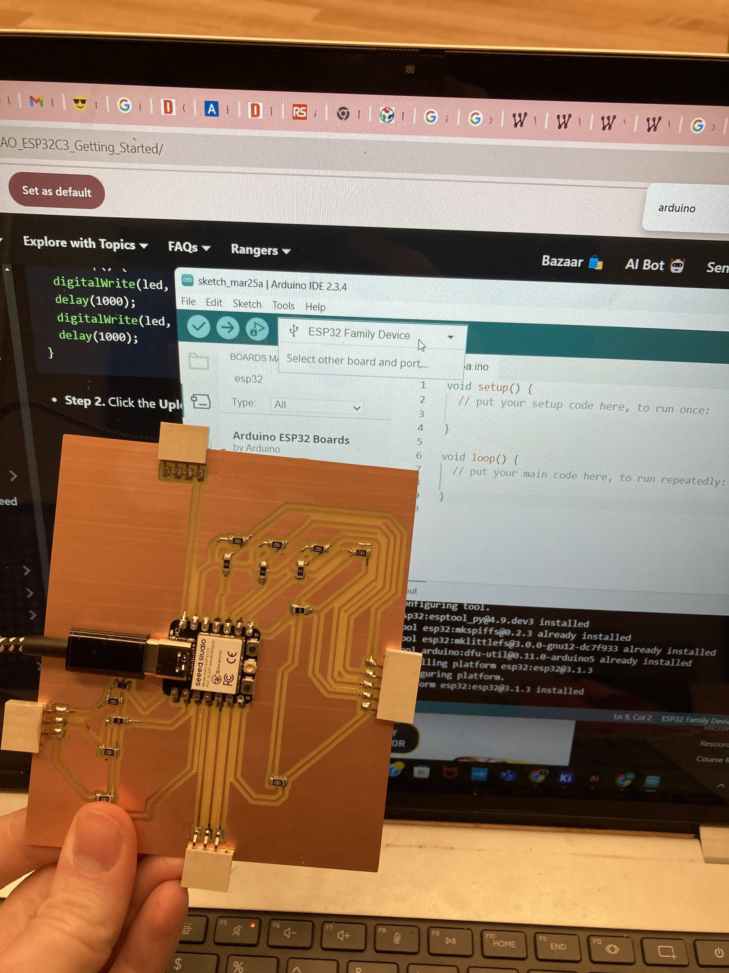
After replacing the melted microcontroller and fixing 3 other issues that I discuss in Week 08, the keypad is fully functional.