
Takeaways: In this activity, two Arduino Unos were connected to separate computers, enabling message exchange between them. To explore wireless communication, a Raspberry Pi Pico W was used to connect to a desktop via Bluetooth. After configuring the board in the Arduino IDE and uploading code, the Pico could receive text, convert it to uppercase, and send it back while blinking its LED. Users connected via Bluetooth settings and used the Serial Monitor to send and receive messages, demonstrating successful wireless communication.
The code handles incoming character streams from two separate serial connections: the hardware Serial port (typically connected to via USB) and a software MySerial port (configured on digital pins 2 and 3 for communication with another device). Instead of processing characters one by one as they arrive, the system uses line-buffering. For each serial port, there's a dedicated character array (serialRxBuffer for Serial, mySerialRxBuffer for MySerial) and an associated index variable (serialBufferIndex, mySerialBufferIndex). As characters arrive, they are read from the respective serial port and sequentially stored into their designated buffer.
An important part of this stream handling occurs when a newline character (\n) is detected. This signals the end of an incoming "line" or "message." At this point, the accumulated characters in the buffer are null-terminated, converting the buffer into a complete C-style string. This complete string is then passed to the containsSwearWord function for analysis. After processing the line (either blocking it and sending a warning, or forwarding it), the index for that buffer is reset to zero, preparing it to collect the next incoming line. This line-by-line processing strategy ensures that complete messages can be evaluated for content before being acted upon.
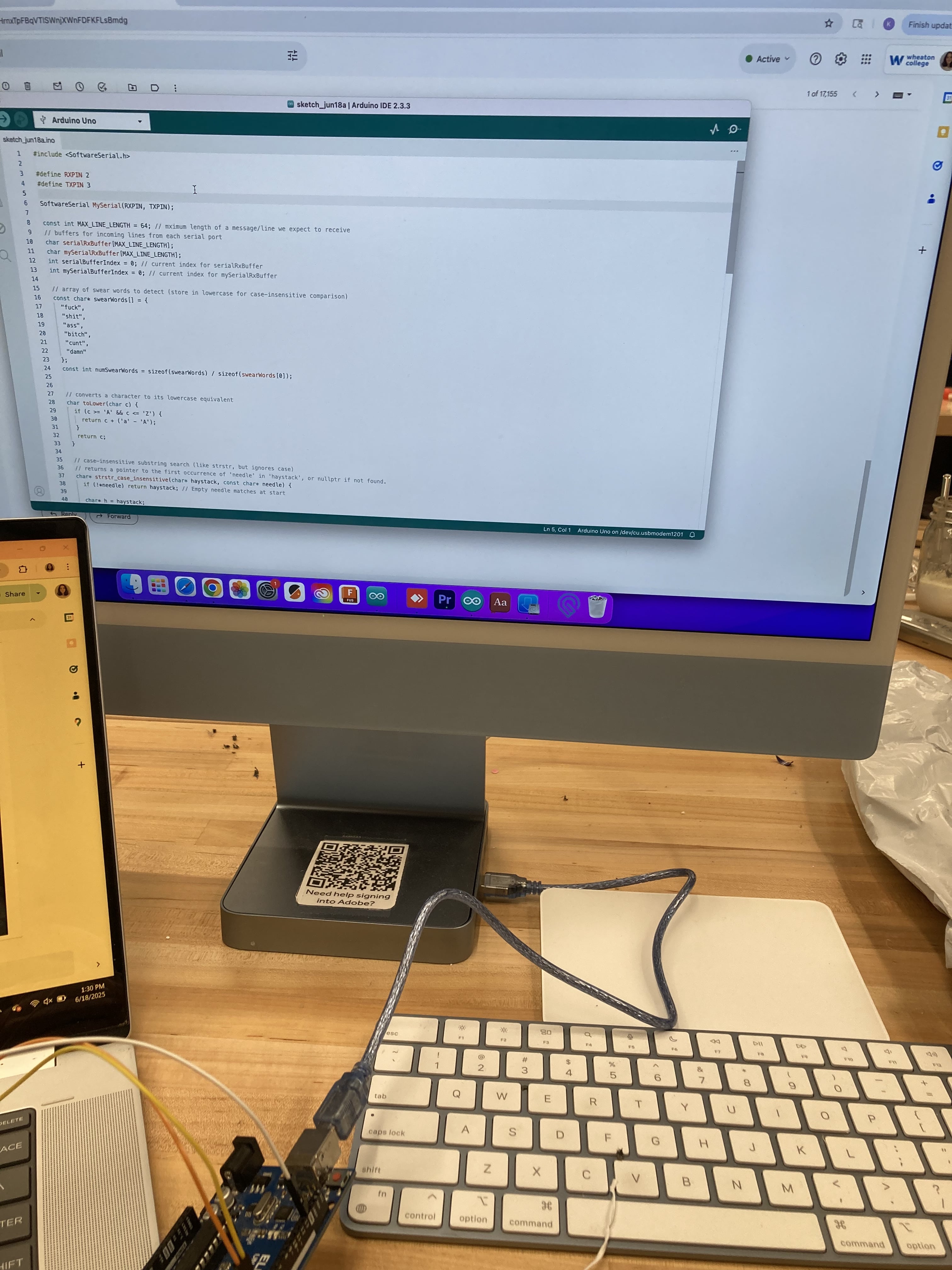
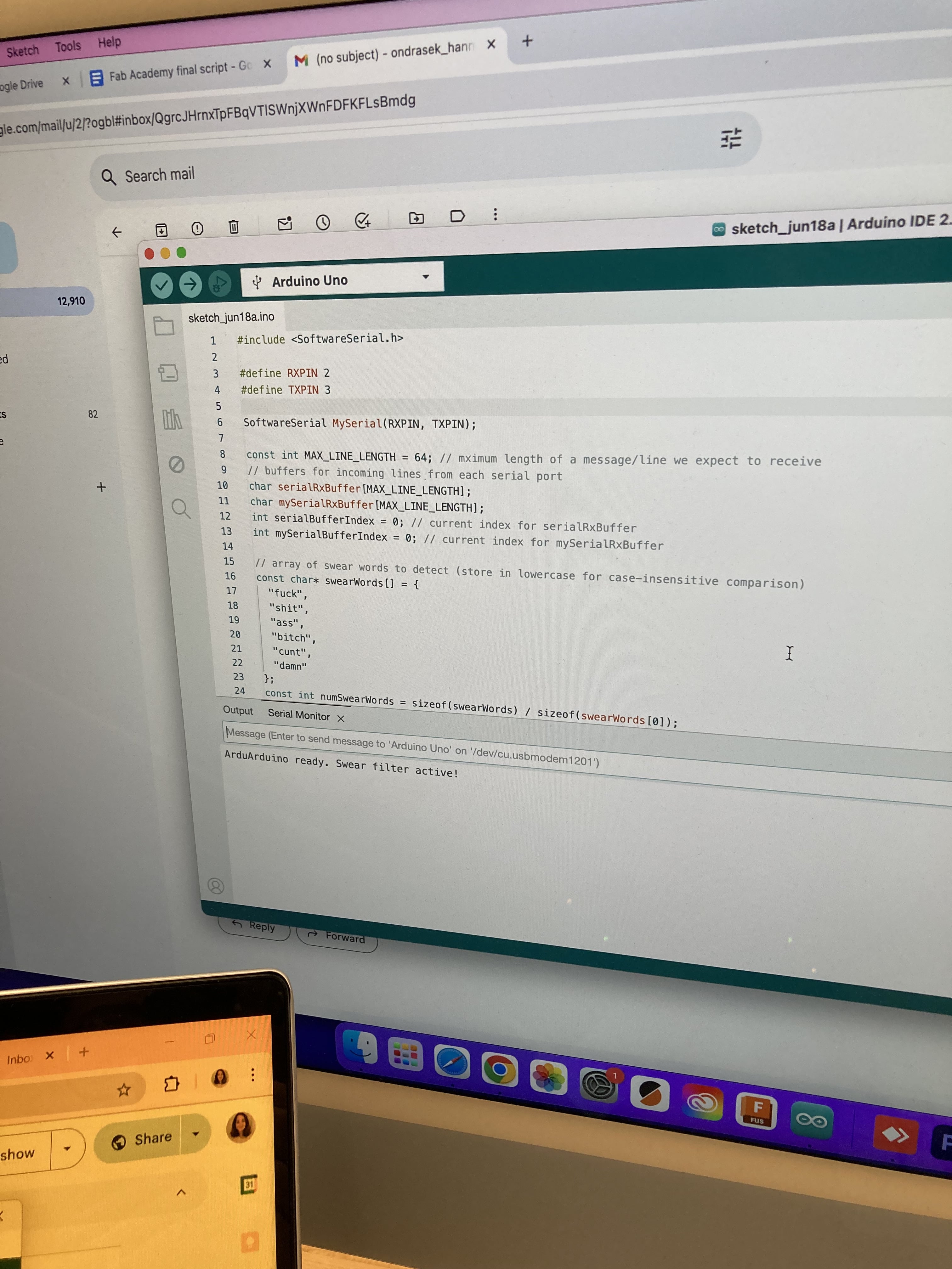
#include <SoftwareSerial.h>


#define RXPIN 2
#define TXPIN 3


SoftwareSerial MySerial(RXPIN, TXPIN);


const int MAX_LINE_LENGTH = 64; // mximum length of a message/line we expect to receive
// buffers for incoming lines from each serial port
char serialRxBuffer[MAX_LINE_LENGTH];
char mySerialRxBuffer[MAX_LINE_LENGTH];
int serialBufferIndex = 0; // current index for serialRxBuffer
int mySerialBufferIndex = 0; // current index for mySerialRxBuffer


// array of swear words to detect (store in lowercase for case-insensitive comparison)
const char* swearWords[] = {
  "fuck",
  "shit",
  "ass",
  "bitch",
  "cunt",
  "damn"
};
const int numSwearWords = sizeof(swearWords) / sizeof(swearWords[0]);


// converts a character to its lowercase equivalent
char toLower(char c) {
  if (c >= 'A' && c <= 'Z') {
    return c + ('a' - 'A');
  }
  return c;
}


// case-insensitive substring search (like strstr, but ignores case)
// returns a pointer to the first occurrence of 'needle' in 'haystack', or nullptr if not found.
char* strstr_case_insensitive(char* haystack, const char* needle) {
  if (!*needle) return haystack; // Empty needle matches at start


  char* h = haystack;
  while (*h) {
    char* h_ptr = h;
    const char* n_ptr = needle;
    while (*h_ptr && *n_ptr && toLower(*h_ptr) == toLower(*n_ptr)) {
      h_ptr++;
      n_ptr++;
    }
    if (!*n_ptr) { // if needle was fully matched
      return h; // return pointer to start of match in haystack
    }
    h++;
  }
  return nullptr; // no match found
}


// checks if the given buffer (a null-terminated string) contains any of the defined swear words.
bool containsSwearWord(char* buffer) {
  if (buffer[0] == '\0') return false; // empty buffer, no swear words


  for (int i = 0; i < numSwearWords; i++) {
    // check for the swear word as a substring within the buffer
    if (strstr_case_insensitive(buffer, swearWords[i]) != nullptr) {
      return true; // found a swear word!
    }
  }
  return false; // no swear words found
}


void setup() {
  Serial.begin(9600);   // initialize hardware serial for communication with computer
  MySerial.begin(9600); // initialize software serial for communication with other device


  Serial.println("Arduino ready. Swear filter active!");
}


void loop() {
  // if a line is received from Serial, process it and potentially forward to MySerial
  handleSerialLine(Serial, MySerial, serialRxBuffer, serialBufferIndex);


  // if a line is received from MySerial, process it and potentially forward to Hardware Serial
  handleSerialLine(MySerial, Serial, mySerialRxBuffer, mySerialBufferIndex);


  delay(5); // Small delay to prevent busy-waiting and allow other tasks to run
}


// inputSerial: The serial port to read from (e.g., Serial or MySerial)
// outputSerial: The serial port to write to (e.g., MySerial or Serial)
// buffer: The character array to store the incoming line
// index: Reference to the current index in the buffer (updates the global buffer index)
void handleSerialLine(Stream& inputSerial, Print& outputSerial, char* buffer, int& index) {
  while (inputSerial.available()) {
    int incomingByte = inputSerial.read();


    // ignore carriage return characters, as Serial Monitor often sends CR+LF
    if (incomingByte == '\r') {
      continue;
    }


    // if a newline character is received, the line is complete, so process it
    if (incomingByte == '\n') {
      if (index > 0) { // only process if there's actual data in the buffer
        buffer[index] = '\0'; // null-terminate the string in the buffer


        if (containsSwearWord(buffer)) {
          // swear word detected!
          inputSerial.println("stop being a pottymouth");


          // inform the debug serial (usually your Serial Monitor) about the block
          Serial.print("[BLOCKED: Potty Mouth Detected from ");
          if (&inputSerial == &Serial) Serial.print("Serial");
          else Serial.print("MySerial (pins 2,3)");
          Serial.print("]: '");
          Serial.print(buffer);
          Serial.println("'");


          // do NOT forward the offensive message to the outputSerial.
        } else {
          // no swear word detected, so forward the line as usual
          outputSerial.print(buffer);
          outputSerial.println(); // add a newline to the forwarded message for clean display
        }
      }
      index = 0; // reset buffer index for the next incoming line
    } else {
      // it's a regular character, add it to the buffer if there's space
      // only buffer printable ASCII characters (32 to 126) to avoid issues with control characters
      if (index < MAX_LINE_LENGTH - 1 && incomingByte >= 32 && incomingByte <= 126) {
        buffer[index++] = (char)incomingByte;
      }
      // optional: Basic backspace/delete key handling for live typing in Serial Monitor
      else if (incomingByte == 8 || incomingByte == 127) { // ASCII 8 is Backspace, 127 is Delete
          if (index > 0) {
              index--; // decrement index to "erase" last character
              // for terminal display, send backspace, space, backspace to visually erase
              inputSerial.print("\b \b");
          }
      }
    }
  }
}
We need 2 computers for this project, connected by USB on each. Pin 3 is connected to 2, and 2 is connected to 3. GND pins are connected to one another. Use male-male jumper cables.
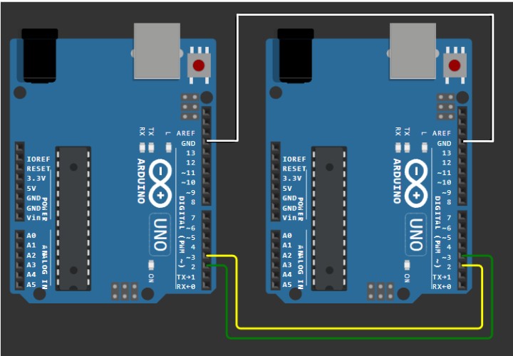
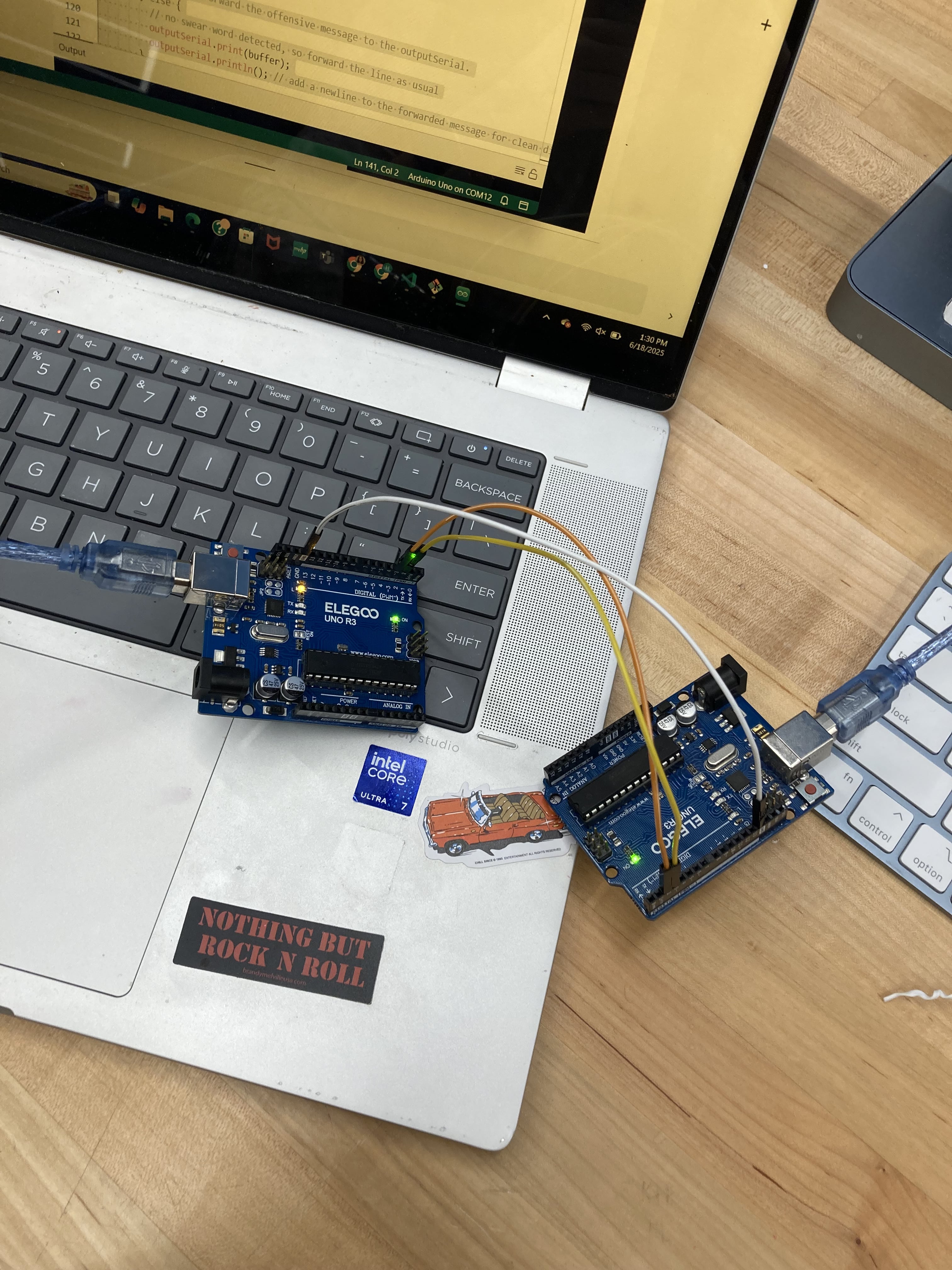
For serial communication between two devices, you always connect a Transmit (TX) pin to a Receive (RX) pin. This "cross-over" ensures that what one device sends, the other receives, establishing the two-way data flow. Connecting the Ground (GND) pins of both devices is also important, as it provides a common voltage reference point, enabling the devices to correctly interpret each other's electrical signals. Below is my setup, with my laptop and one of the lab computers.
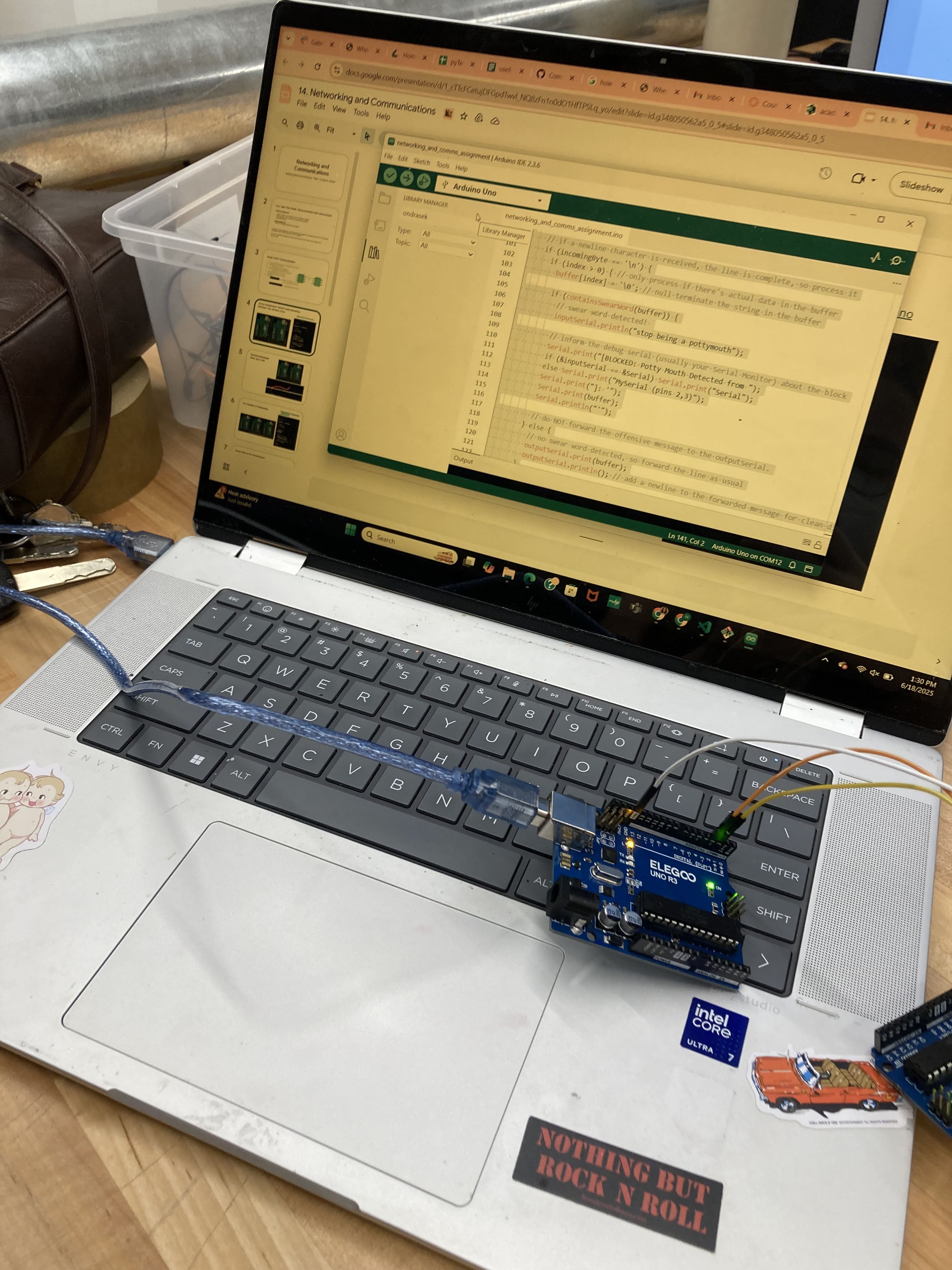
Code successfully uploaded on both machines, since the serial monitor shows the setup serial message ("Arduino ready. Swear filter active!").
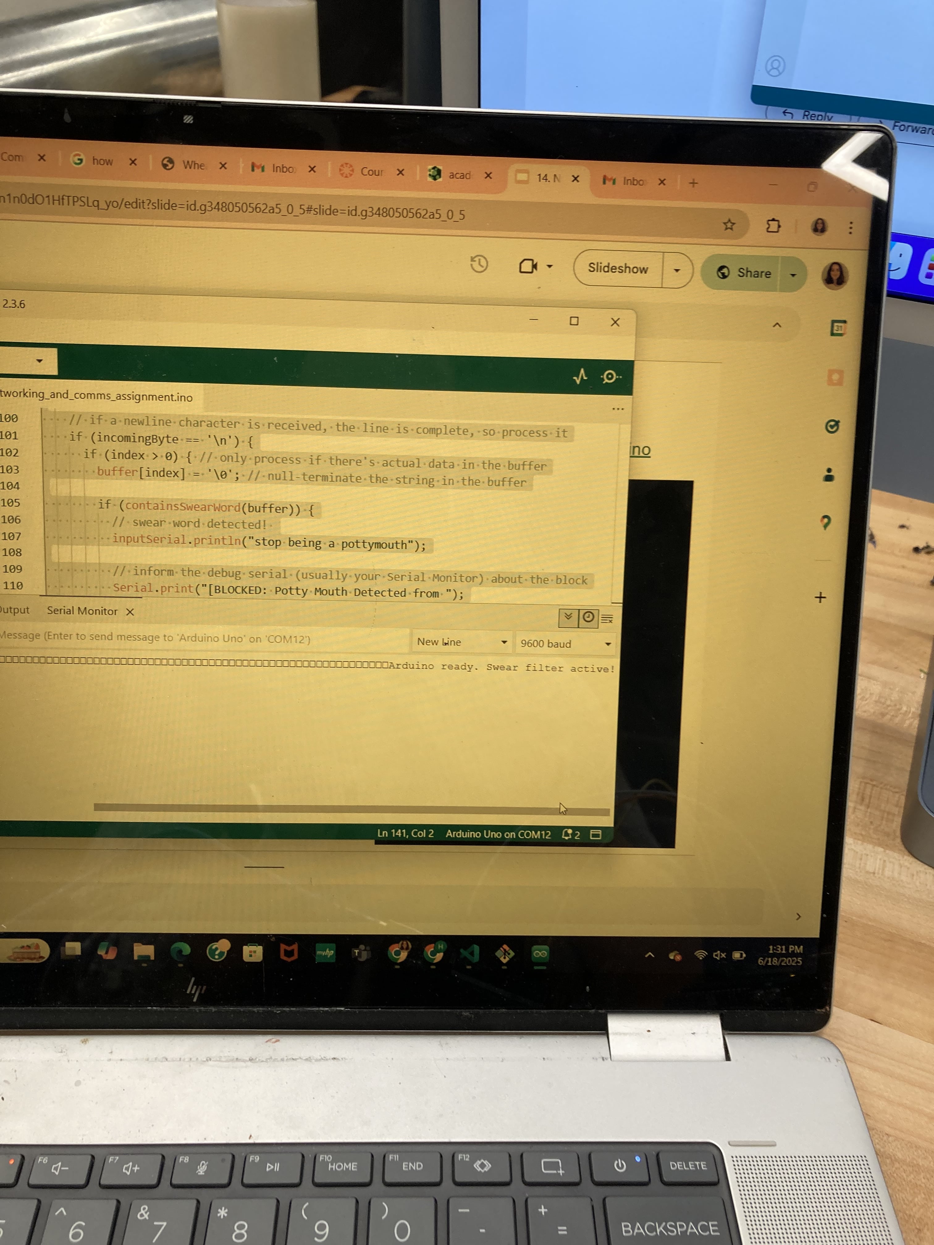
Type a message into the serial monitor, and it should appear on the serial of the other connected computer. That is, unless, a swear is detected, and the message is not sent to the other serial monitor. The user receives a warning message.