
Takeaways: To determine the power consumption of our servo motor, we measured the voltage and current while the motor was running and after we manually stopped it (stalled motor). We found that the power consumed by the stalled motor was about 100x greater than the power consumed by the motor running as usual. This is because the measured current was much greater for the stalled motor than for the running motor. Current is represented by I in the P=V*I equation. A stalled motor could evenually result in burning out the microcontroller as the current is much too high for much too long.
I used my code from week 4 and all I had to do was modify some of the lines to reflect the liquid crystal library, for example:
        display.println(key);
        display.display();
to
lcd.print(customKey))
        #include <Keypad.h>
          #include <LiquidCrystal_I2C.h>

          // Define Keypad Rows and Columns
          const byte ROWS = 4;
          const byte COLS = 4;

          // This should match your actual keypad layout
          char keys[ROWS][COLS] = {
            { '1', '2', '3', 'A' },
            { '4', '5', '6', 'B' },
            { '7', '8', '9', 'C' },
            { '*', '0', '#', 'D' }
          };

          LiquidCrystal_I2C lcd(0x27, 16, 2);

          // Change these to match your actual ESP32 GPIO connections
          byte colPins[COLS] = {21, 4, 3, 2};  // GPIOs connected to keypad columns
          byte rowPins[ROWS] = {20, 8, 9, 10};  // GPIOs connected to keypad rows
          Keypad customKeypad = Keypad(makeKeymap(keys), rowPins, colPins, ROWS, COLS);


          void setup(){
            Serial.begin(9600);
            lcd.init();
            lcd.backlight();
          }

          void loop(){
            char customKey = customKeypad.getKey();

            if (customKey != NO_KEY){
              Serial.println(customKey);
              lcd.clear();
              lcd.setCursor(0,0);
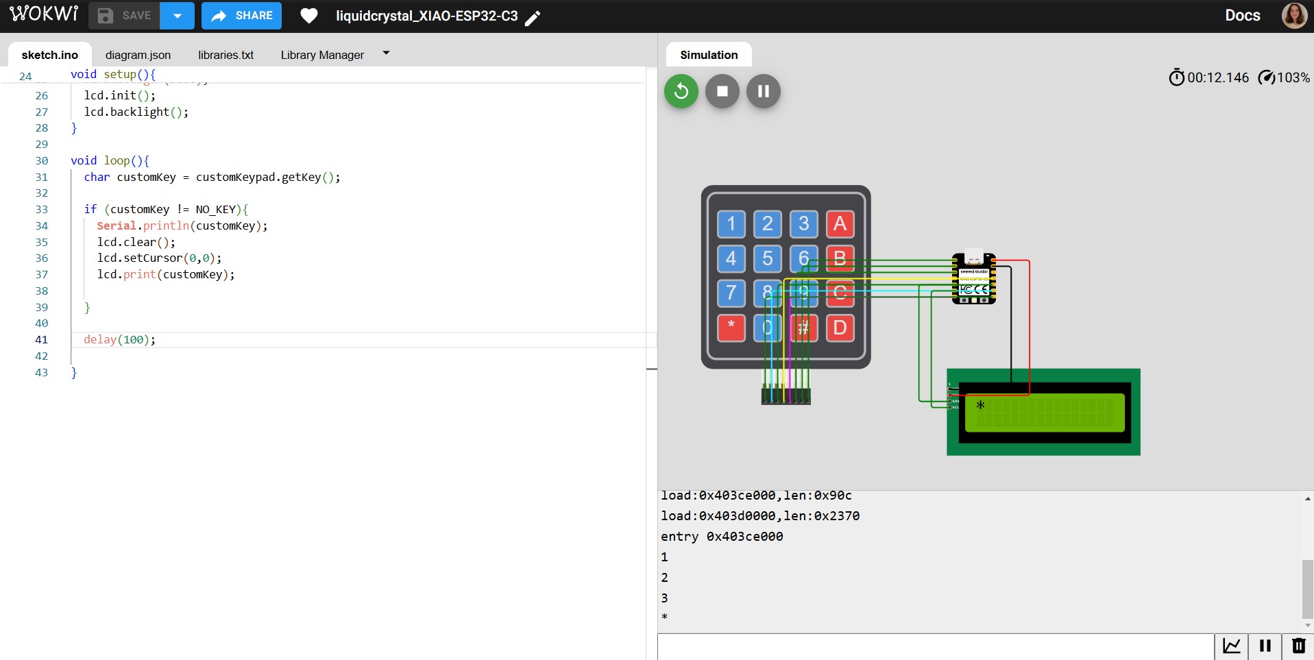
              lcd.print(customKey);

            }

            delay(100);

          }
First, I wanted to make sure the lcd screen with backpack would work on a basic level (just printing something random). Use the liquidcrystal i2c library for this particular device.
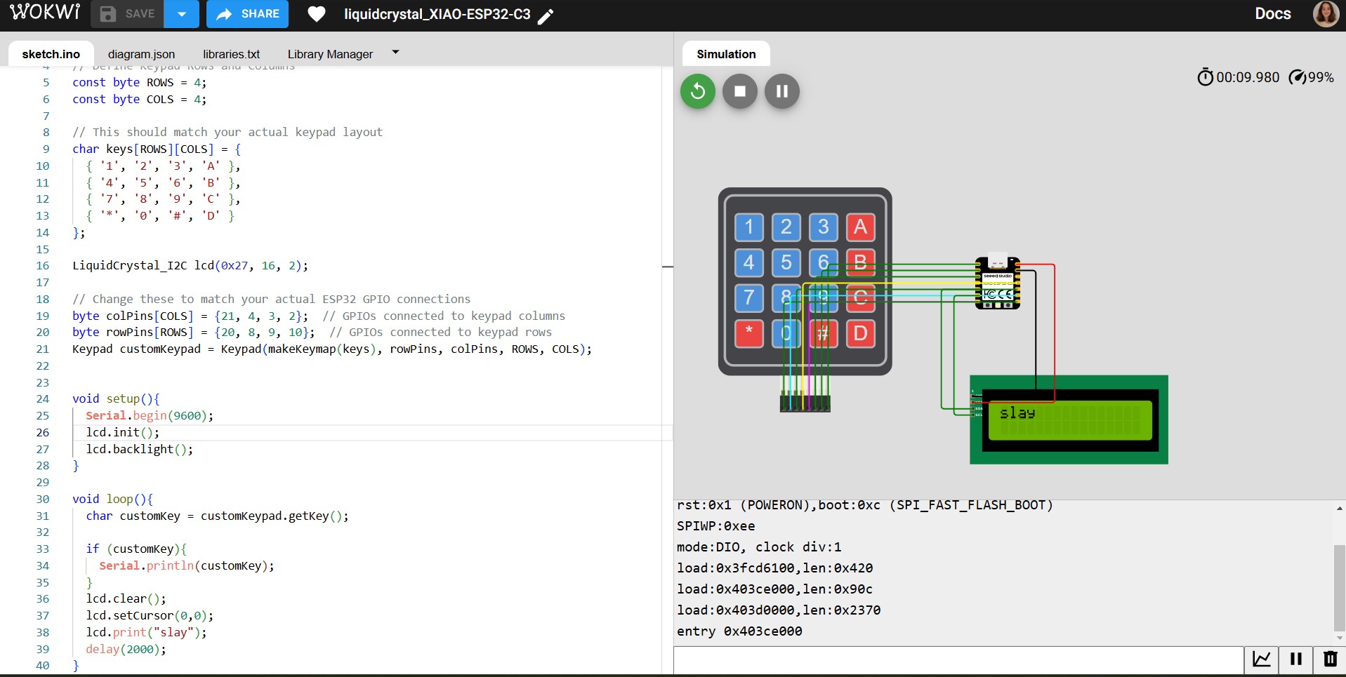
The finished program for making the keypad input show up as an output on the screen.
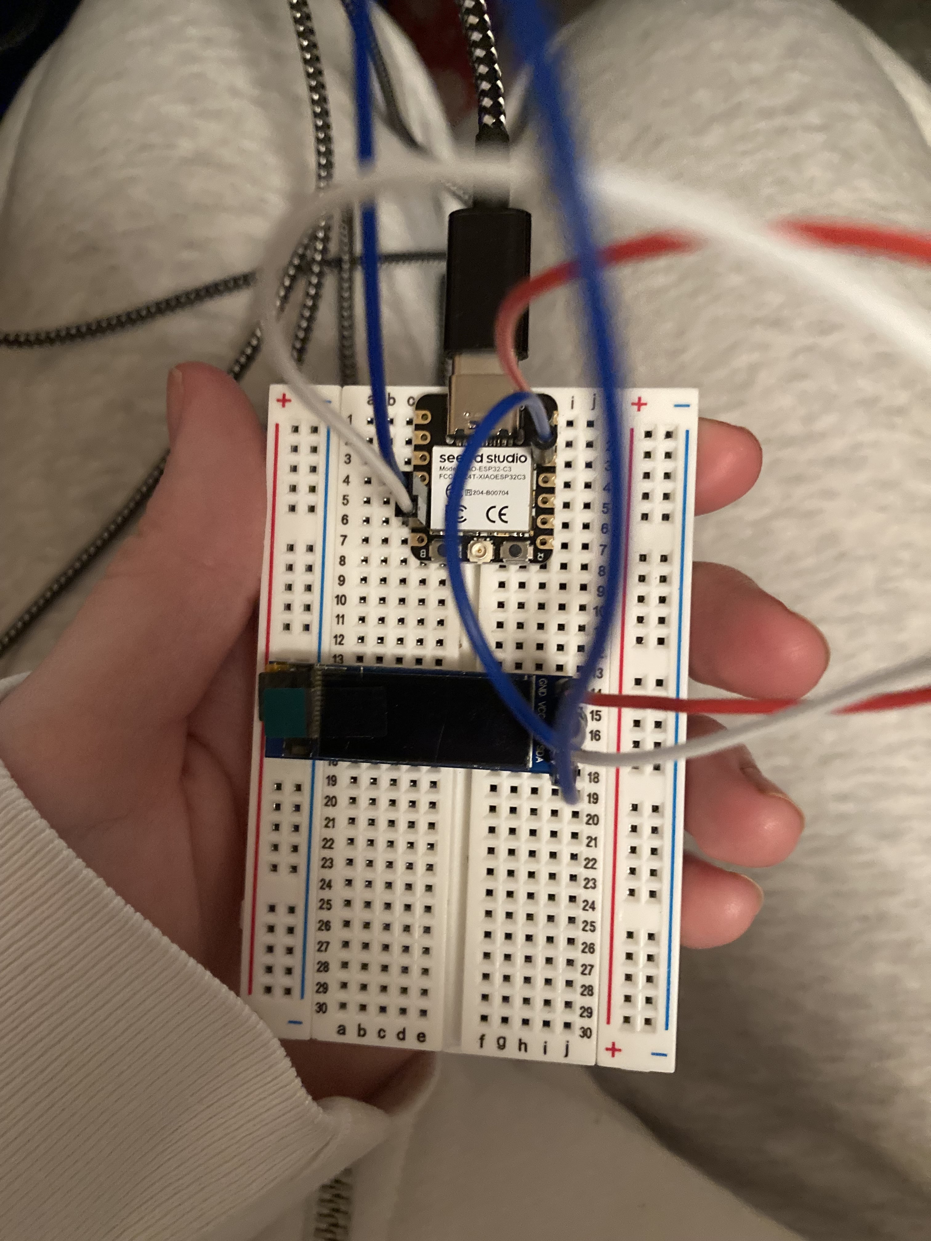
I tried using this 4 pin I2C display module from Amazon rather than the lcd display with I2C backpack module, but there were a few issues with using this particular device. First, it requires 3.3V, which I did not have a pin header for. Second, when I tested it below, it appeared to not work at all. Finally, the code was a little unintuative, and I had to look through the Amazon reviews to get sample code. Despite using the sample code, the device still did not seem to work.
When using one of these lcd keyboards with an I2C backpack module, we plug a male-female jumper cord from the backpack module into the microcontroller. I found this easiest to use because I already had 5V and SDA/SCL pin headers. This is an example diagram in Arduino. With the backpack soldered on, we only need 4 connections (SCL, SDA, VCC (power), and GND) rather than the many required for using an lcd display alone.
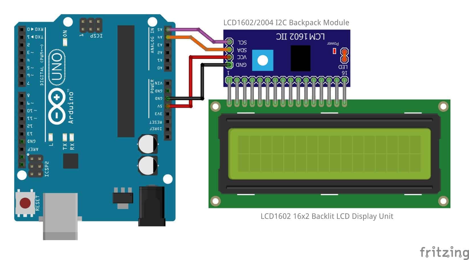
Attach male-female cables to these pins and their correspondingly labelled backpack sockets:
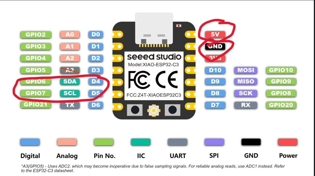
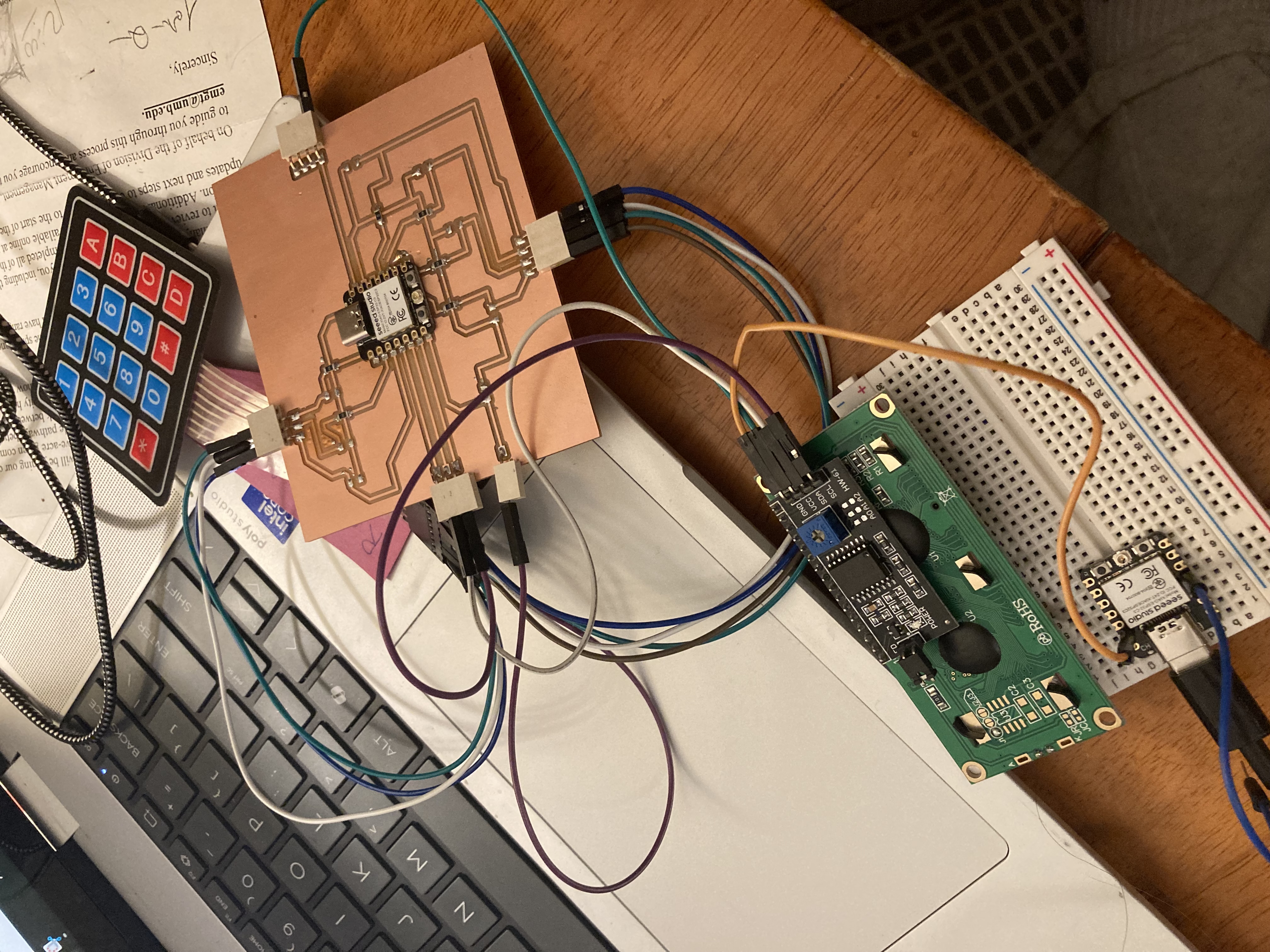
The final board (I need to attach a pinheader for GND, for the working version I held the GND wire to the GND socket of the microcontroller):

The functionality of the devices in action: