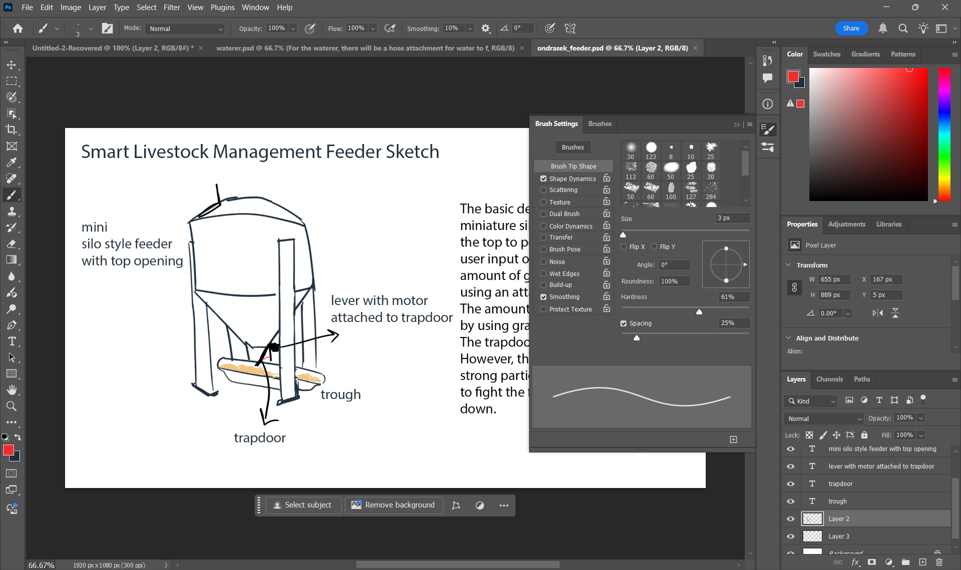
I used photoshop because of the move-ability of layers & the variety of brush tools. I used Fusion 360 because of its unique features, such as offering threads & many different materials.
For the text in my final designs, I used Photoshop's text tool:
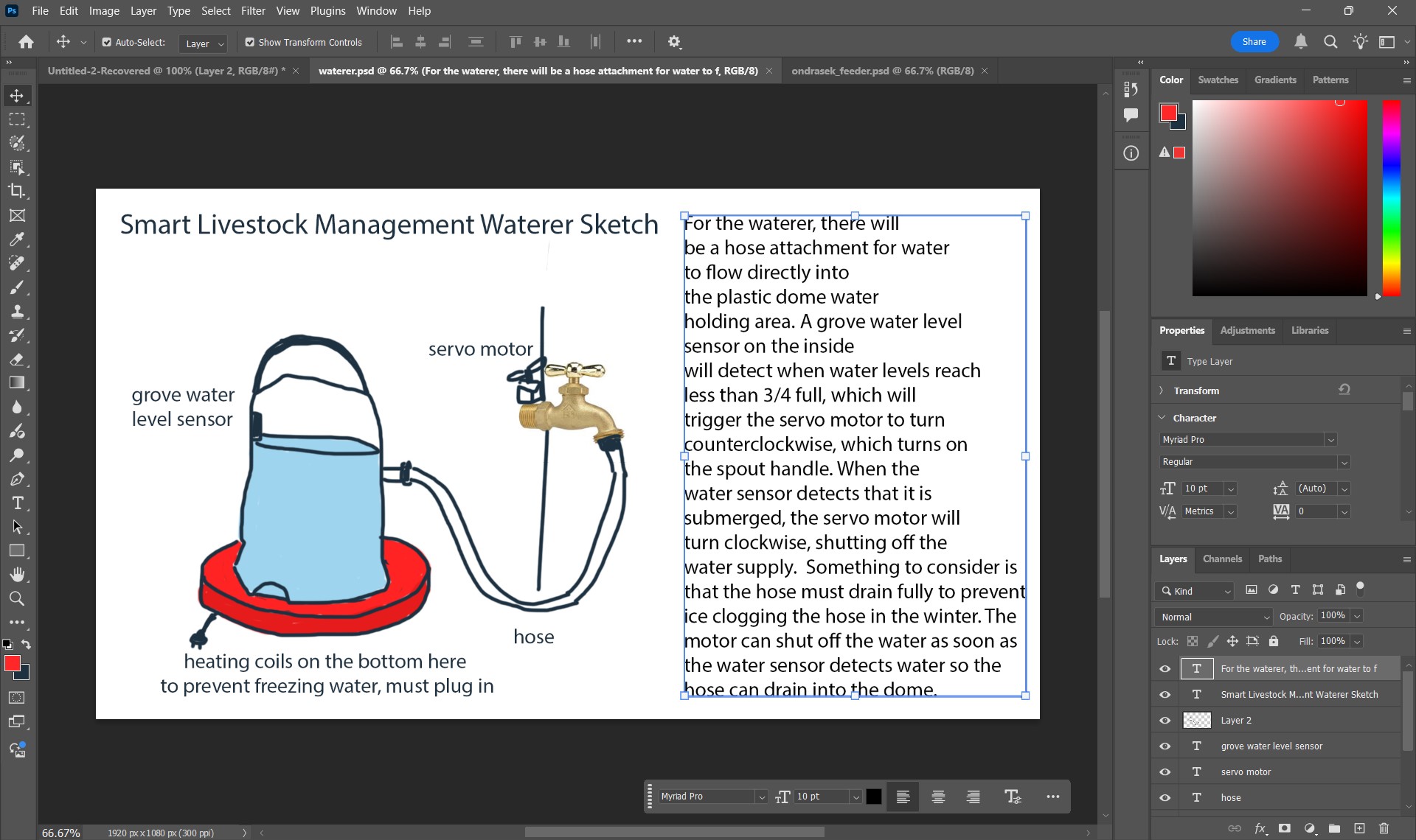
For the actual sketch part of my final designs, I used one of Photoshop's brush tools. I also utilized layers to make some text/drawings appear on top of another. Make a new layer by using Ctrl + Shift + N.
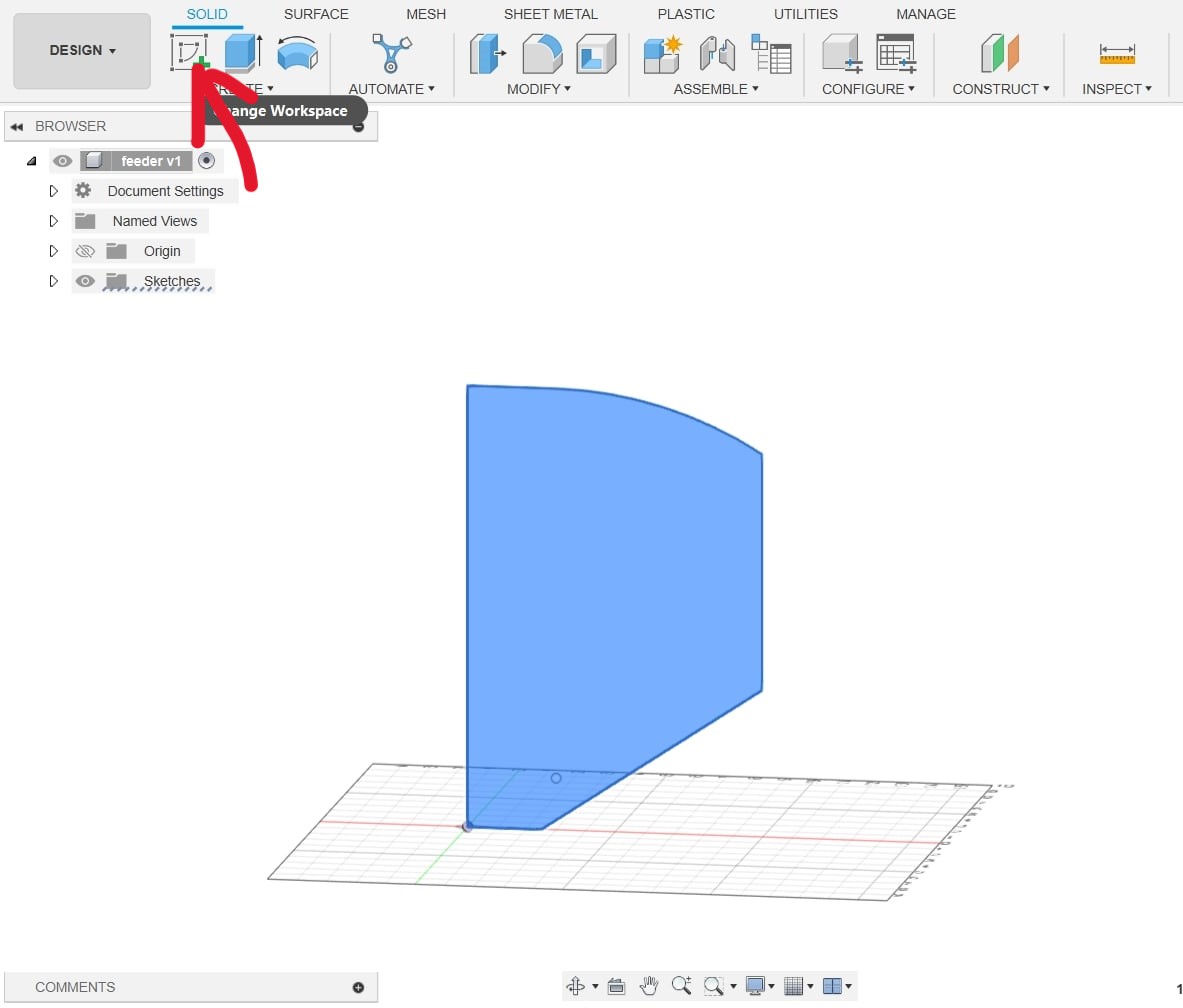
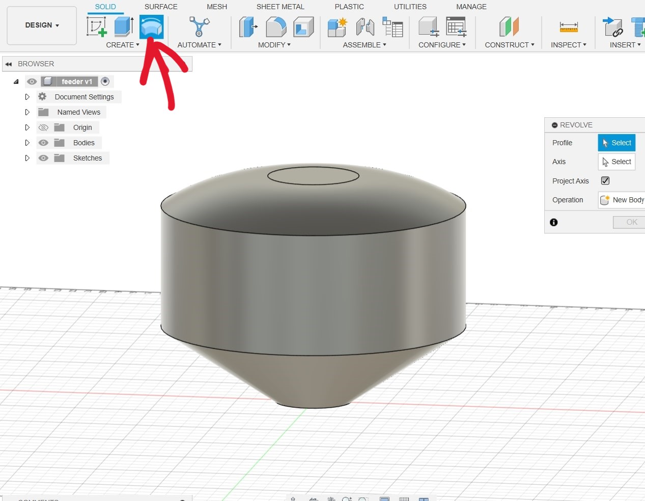
To begin, I started by making a sketch of half of a silo-shaped feeder. I did this by clicking Create Sketch, and using the line tool. To make a curved line, I left-clicked, but continuously held my finger on the left mouse button.
Next, I used the revolve tool to make my design three dimensional. I selected the axis to be the leftmost line of my sketch because I wanted that to be my center axis.
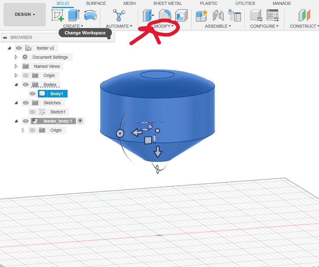
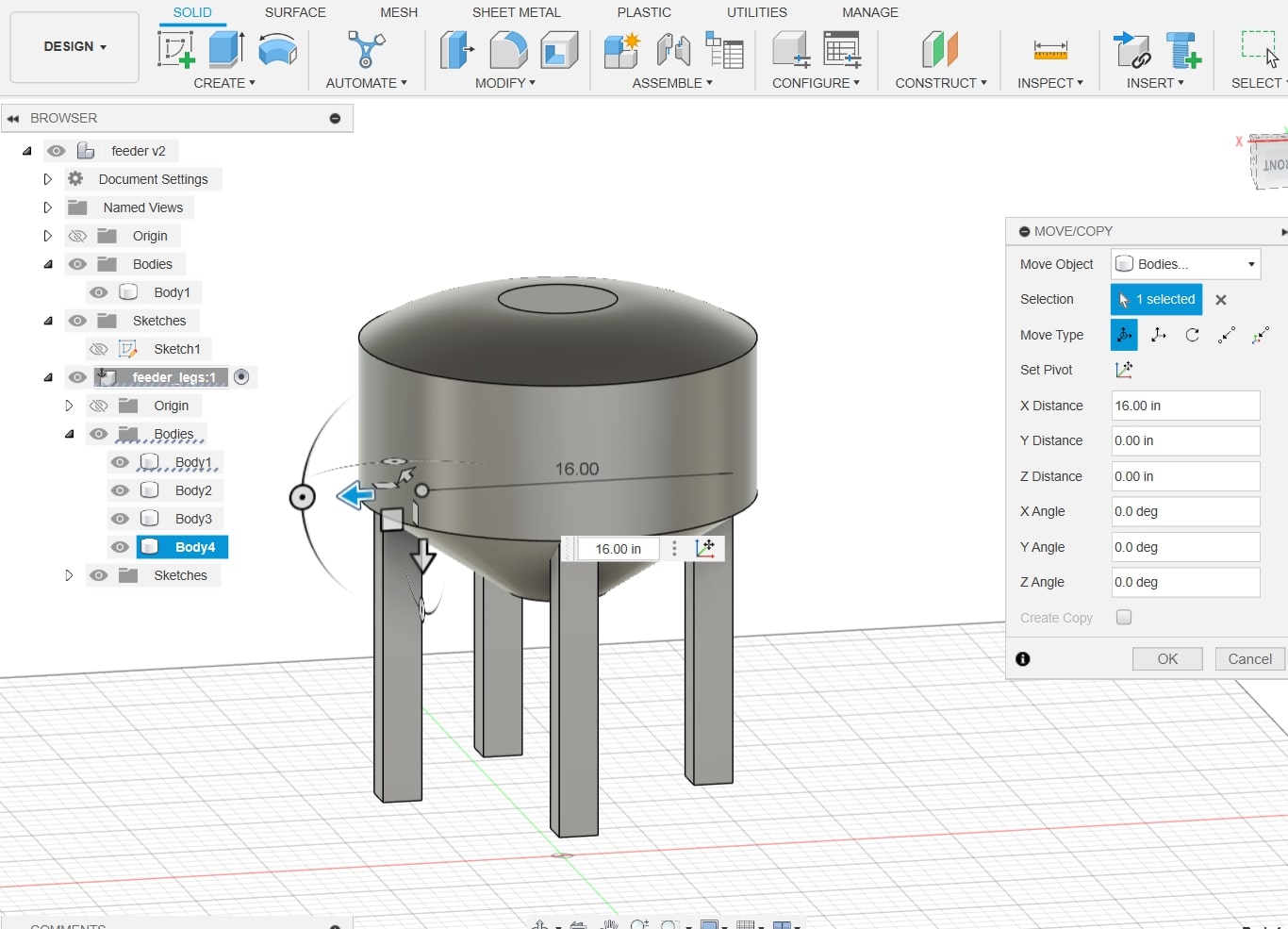
I decided to move my design upwards because working on the legs would get confusing if they were below the axis. I did this by clicking Modify > Move/Copy.
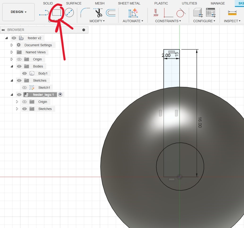
I began working on the legs, which I did by using Create Sketch > Rectangle tool. I needed the dimensions of the legs to be consistent as I was going to copy this design 3 times to make 4 legs.
After I finished designing one leg, I simply copied and pasted the design by pressing Ctrl + C and Ctrl + V (I am a windows user), where after pasting, fusion automatically opens the move menu.
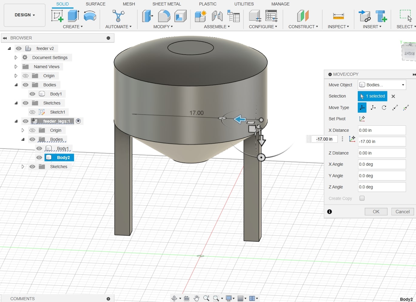
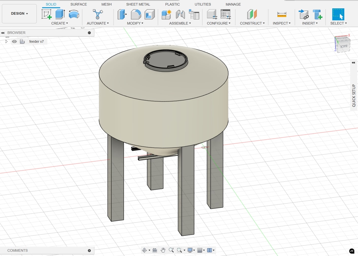
Below is the design with all 4 legs attached.
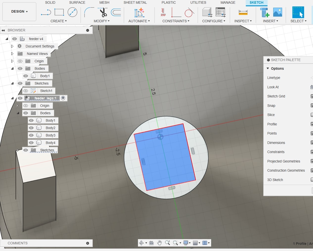
I began creating the outline for a hole that would become the hatch for the silo, where grain would be poured out. To do this, I went Create Sketch > Rectangle tool.
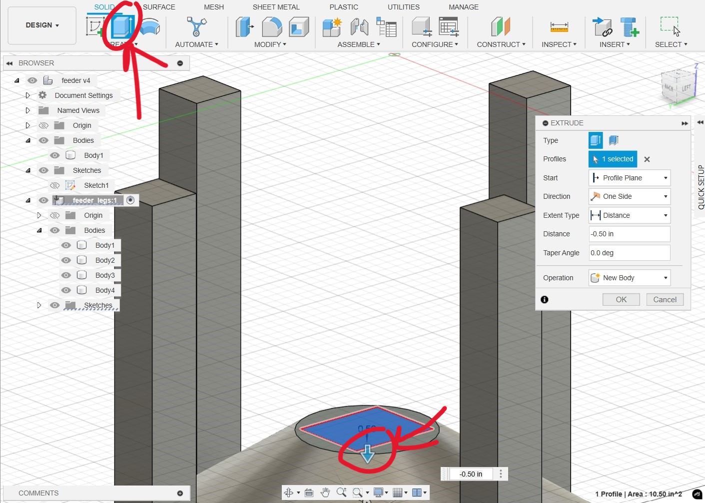
To actually cut this "hole" in my design, I clicked Extrude, and rather than extruding upwards, I pressed and held the arrow key downwards to cut the rectangle shape into the silo design.
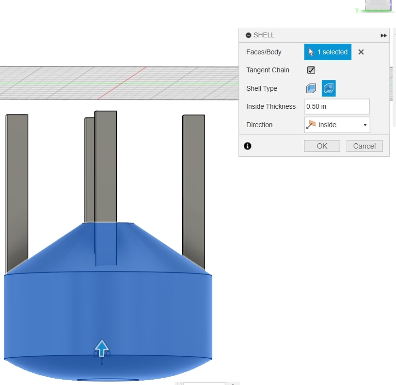
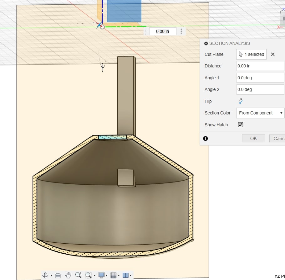
In order for the silo to actually hold grain, it is necessary to make sure the design is hollow. To do this, I clicked Modify > Shell. I made sure the corners of the shell were rounded, as some parts of the design are definitely round.
Section analysis below to ensure that the hollowing process worked (Inspect > Section Analysis).
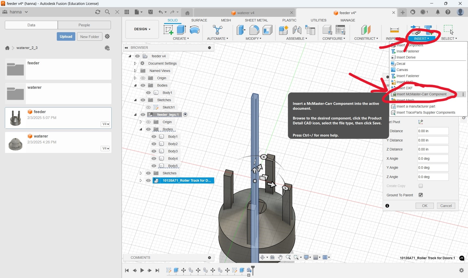
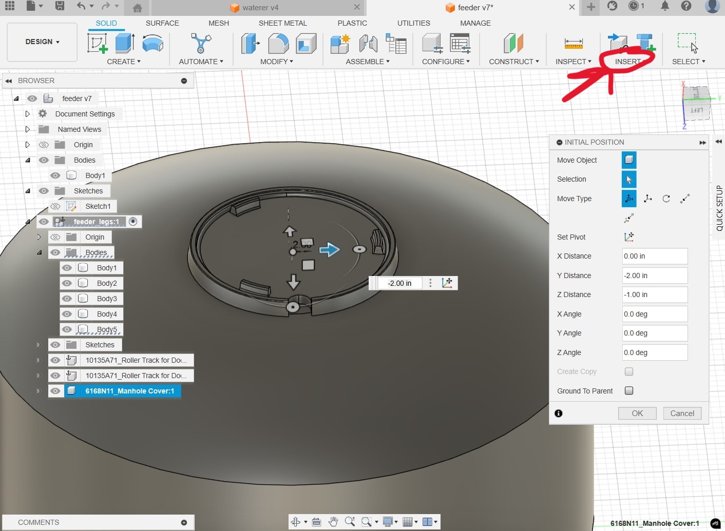
I realized that a regular door hinge design for a hatch would not work for the bottom. I decided that a sliding door mechanism would be better, so I wanted to insert a sliding door track. I inserted a McMaster-Carr sliding track component, which I did by clicking Insert > Insert McMaster-Carr Component and searching for a sliding track, where it gives you the option to download a 3-D SAT version of the item.
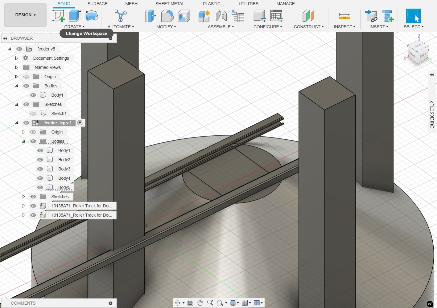
I moved the track to press against the bottom, and I copied the item so I would have two tracks where the openings would face each other. The tracks were very long, extending past the edge of the silo, so I would need to cut them with the extrude tool later.
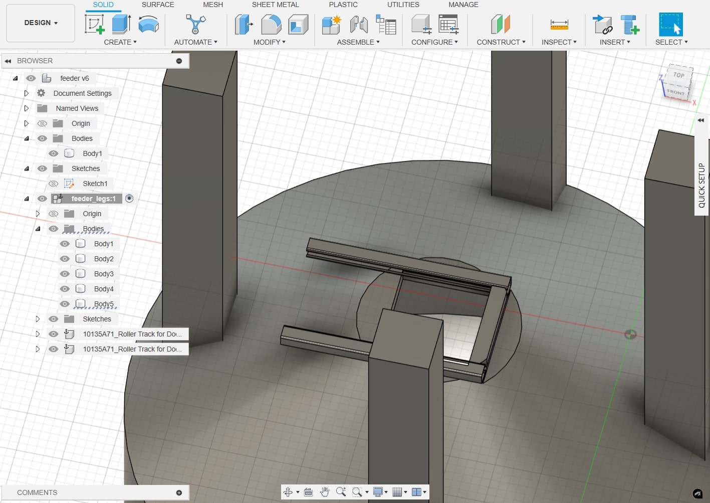
The tracks after I used the extrude tool to delete the excess track:
I inserted another McMaster-Carr component (Insert > Insert McMaster-Carr Component) for the top opening, where grain would be poured in. I decided to use a plastic manhole cover to give myself an idea of a circular trapdoor sort of design I could use for an upwards circular opening.
Finishing touches of the physical material of the design. I changed the material by right-clicking an object, and pressing 'Physical Material'. I then dragged and dropped the material name and picture onto the design.
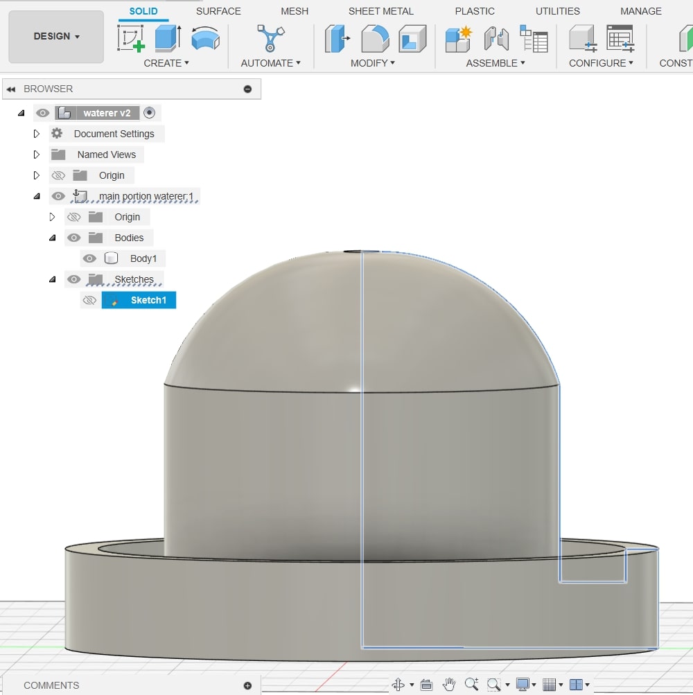
To begin, I started by making a sketch of half of a traditional chicken waterer. I did this by clicking Create Sketch, and using the line tool. To make a curved line, I left-clicked, but continuously held my finger on the left mouse button. Then, I used the revolve tool to make my sketch 3 dimensional, choosing the axis as the leftmost line.
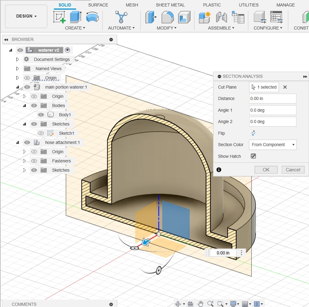
To store water, we must make the cylinder portion of the design hollow. I clicked Modify > Shell and selected rounded edges for the cylindrical design. Below is a cross section proving that my design is hollow.
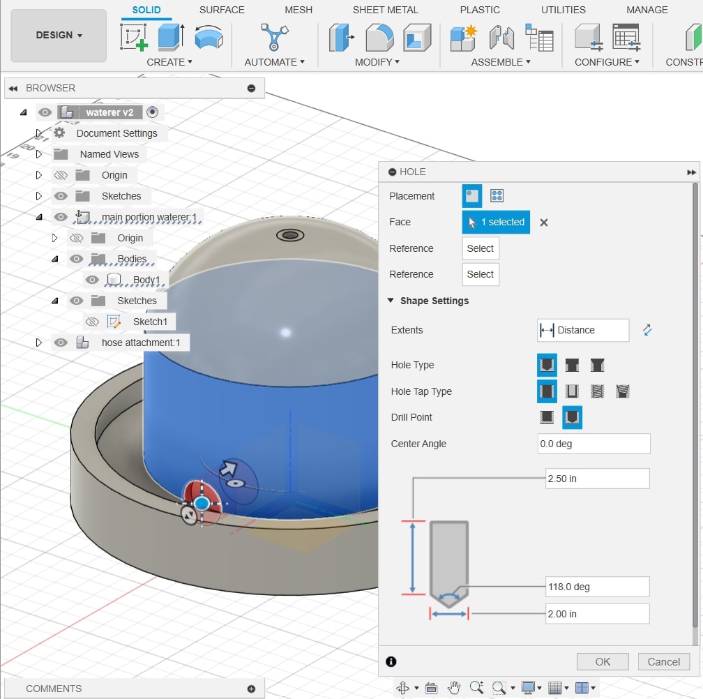
In a typical waterer design, there is a small semicircular hole where the water comes out of the waterer using the force of gravity. I wanted to replicate this in my design, so I clicked Create > Hole, as this is the only way to make a hole in a cylinder.
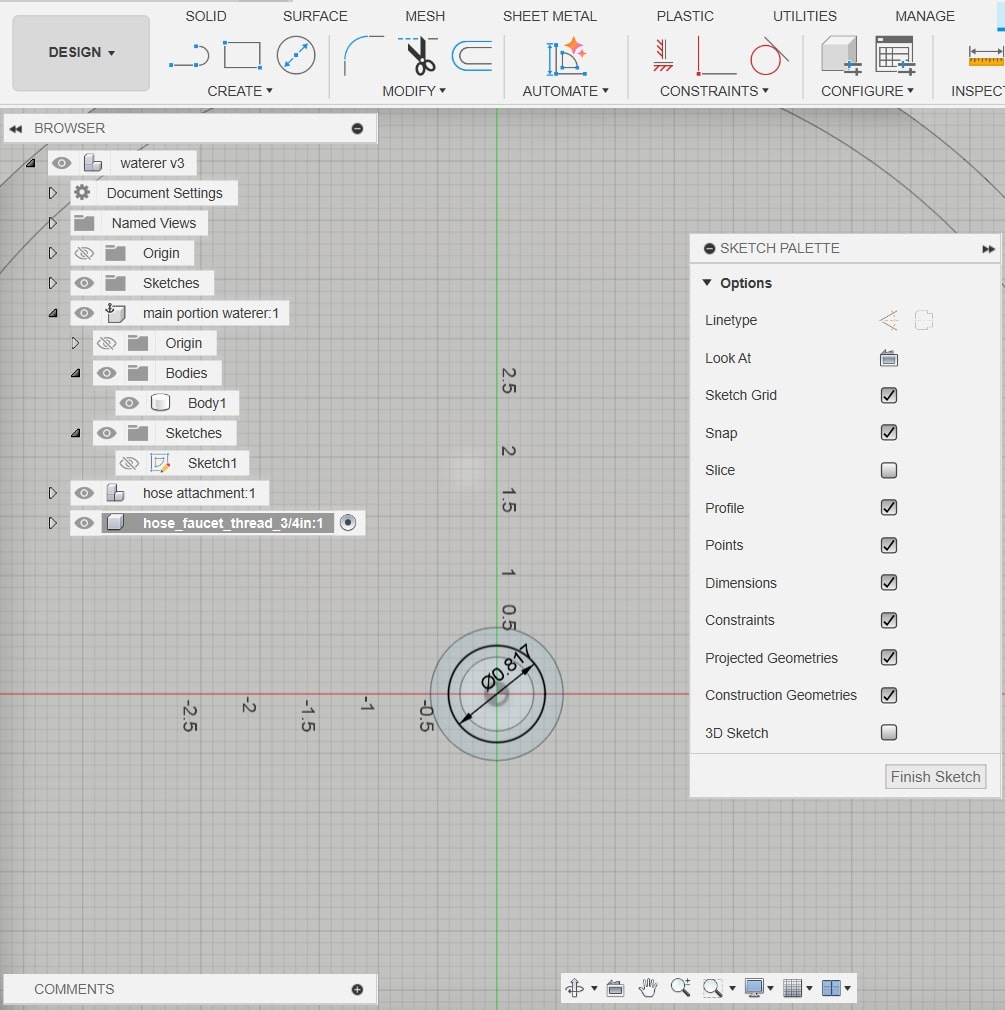
Next, to make the hose attachment, I sketched a hole where the inner shell of the tube would be exactly 1/6" thick. I also made sure the inner hole would be the diameter of a garden hose, 3/4". To do this, I did Sketch > Circle tool, and I set the diameter as I made the circle.
The hole at the top of the design:
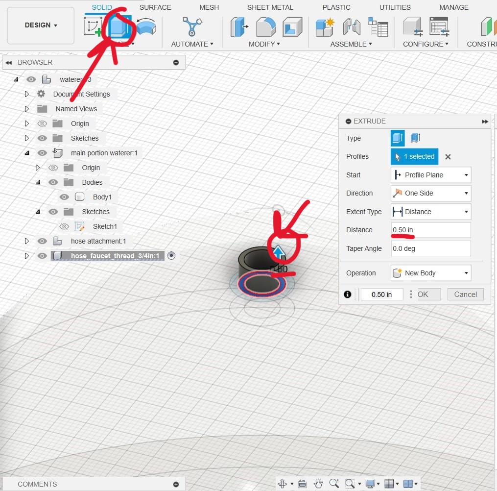
Next, to make the tube/faucet connection, I clicked Extrude, then the upwards arrow key after I selected the sketch. I decided to make the tube length 1/2".
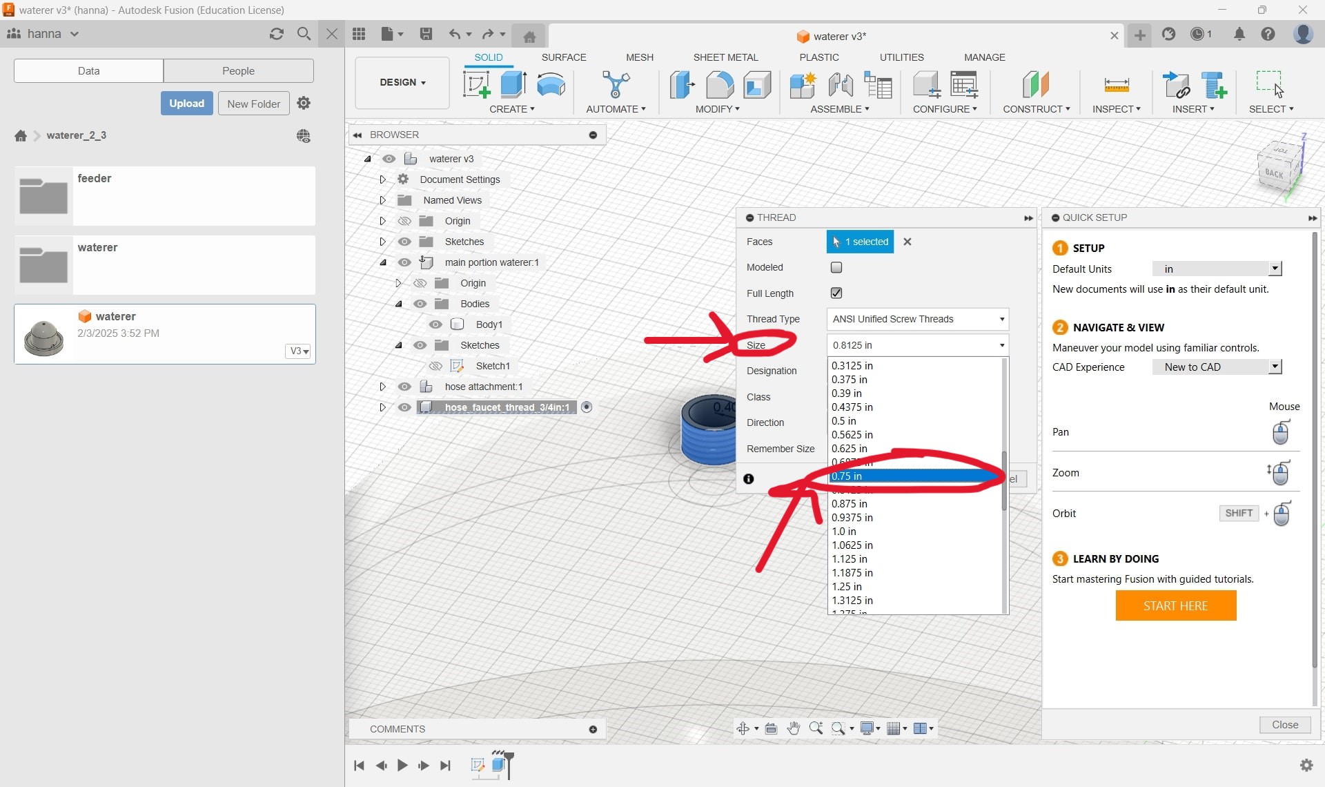
To make a connection with a hose, garden faucets have a ribbed metal material, called a thread, where you twist the end of the hose. To make a thread on my design, I clicked Create > Thread. I applied the thread to the tube.
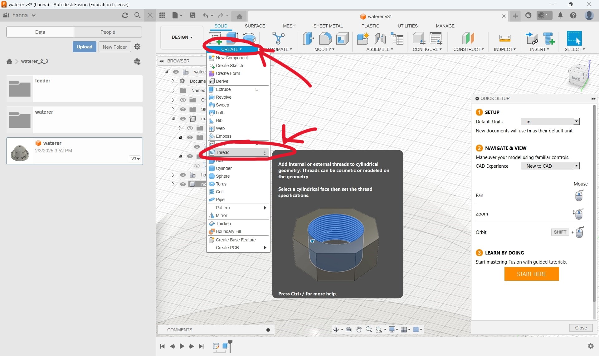
I made the thread size 3/4", which is the thread size of a garden hose connection. With this, I've finished the hose connection part of the design, for now.
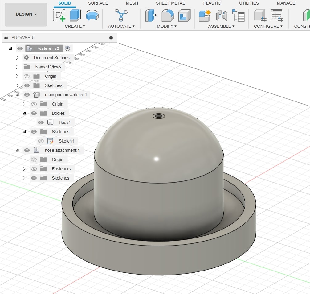
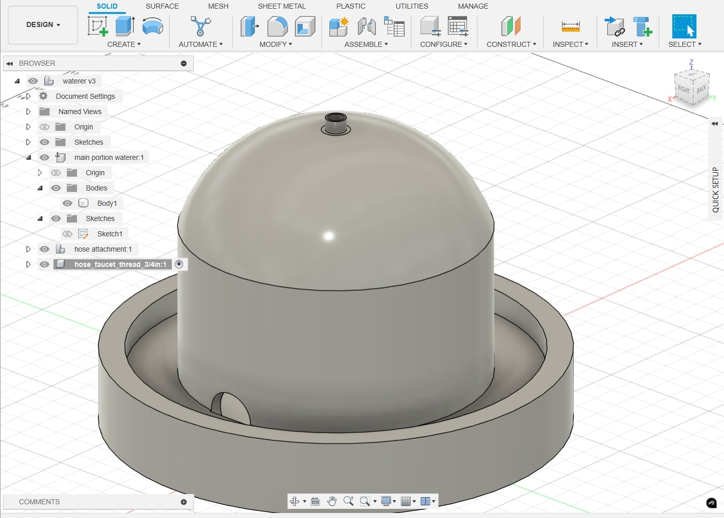
I applied a plastic finish to my design. Below is the finished waterer.
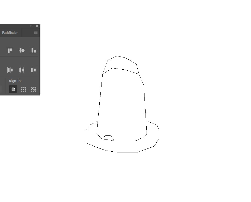
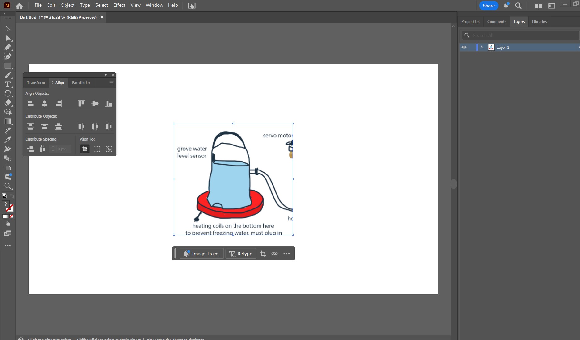
First, I put in a photo of the waterer into illustrator for the purposes of making it a template for a vector design. It is much easier to make vector designs in illustrator than it is to use photoshop.
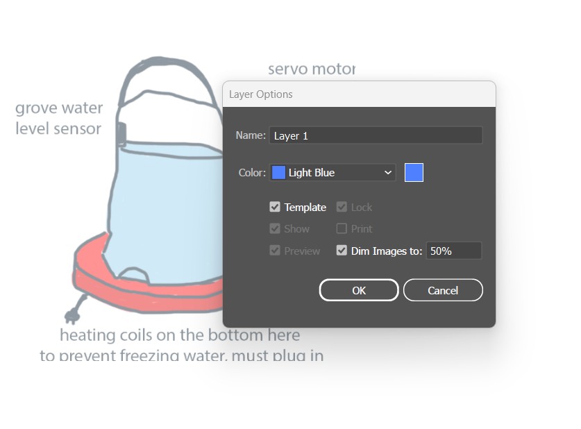
Second, I made sure the layer the photo was on was a template. This will also us to make it easily traceable.
Make a new layer, which is where the vector design will be. I used the pen tool to make a vector trace design.
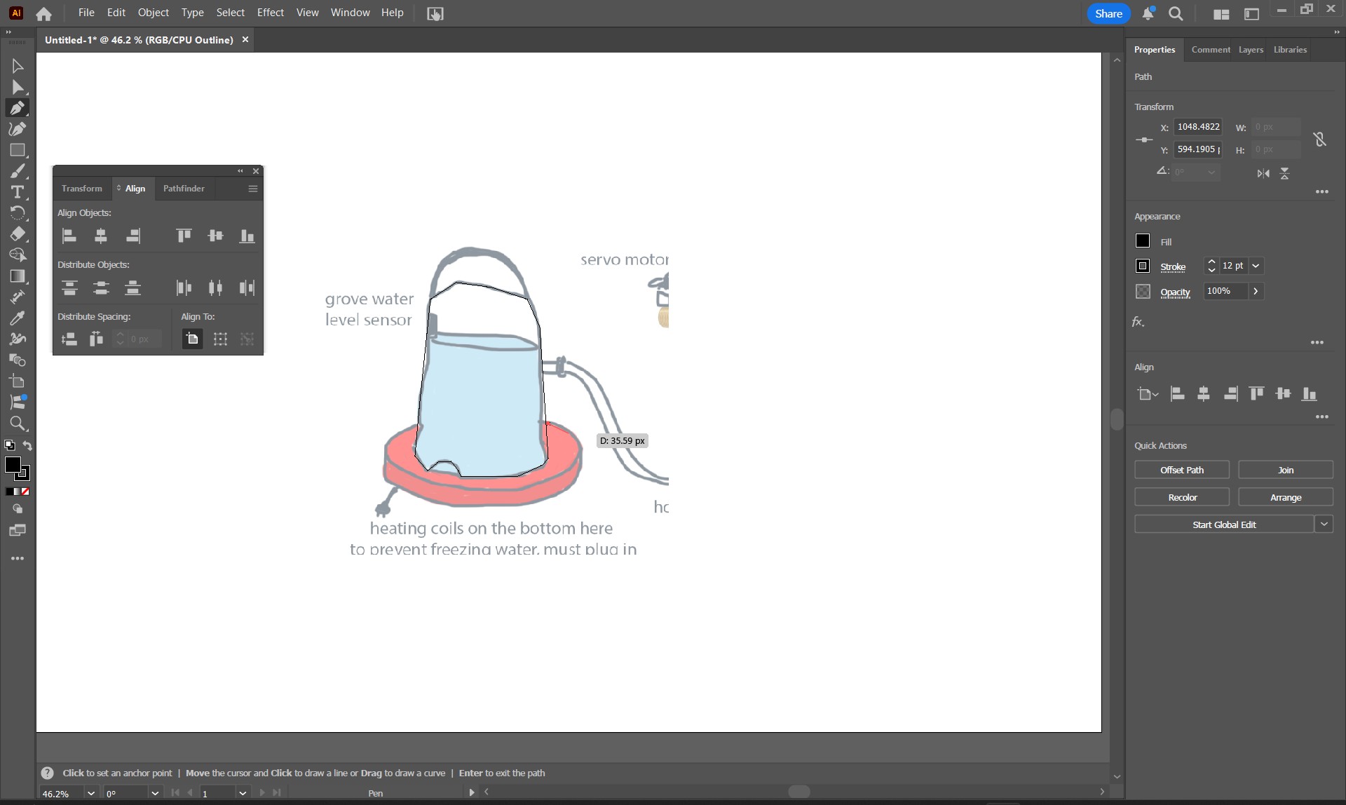
The finished vector design.