Embedded Networking and Communications
Overview of week 11
Group Assignment
- Send a message between two projects
Individual Assignment
- Design, build and connect wired or wireless node(s) with network or bus addresses and a local input and/or output devices
Group Assignment :
Individual Assignment :
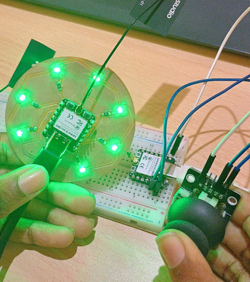
Hero shot
Networking and Communications
Embedded Networking and Communications involve enabling microcontrollers and embedded systems to exchange data with each other or external devices. It includes protocols like UART, SPI, I2C for short-range communication and Ethernet, Wi-Fi, Zigbee, Bluetooth for broader networking.
Wired Communication
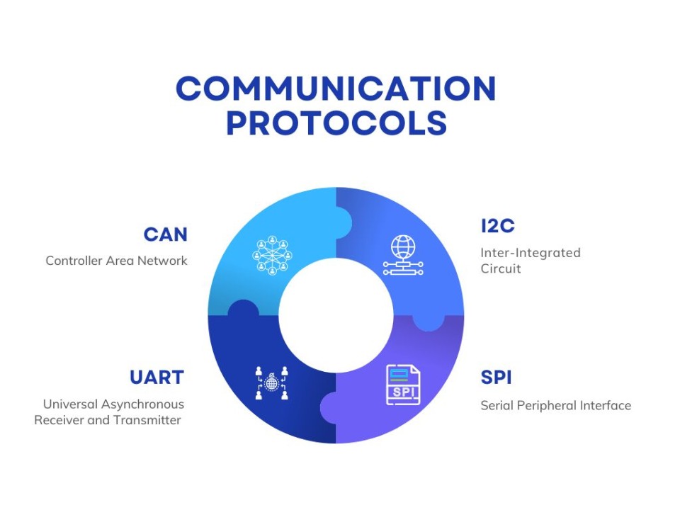
Wired communication in embedded systems uses physical cables to transmit data between devices. Common protocols include UART (for serial data), SPI (for high-speed device communication), and I2C (for multi-device networks).
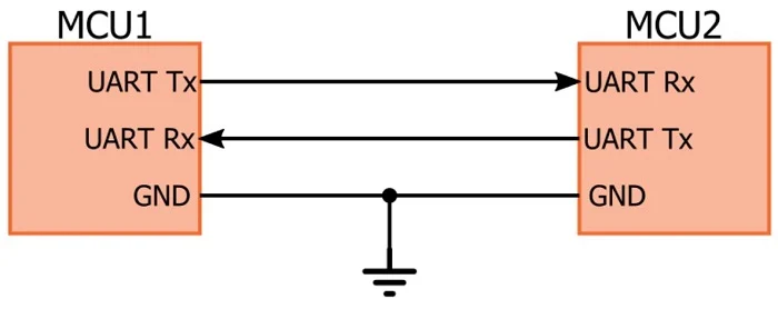
UART (Universal Asynchronous Receiver/Transmitter)
- Point-to-point communication using TX and RX lines.
- Asynchronous: No clock signal required.
- Common baud rates: 9600, 115200, etc.
- Simple and widely used in serial terminals and debugging.
- Supports only two devices (one sender, one receiver).
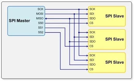
SPI (Serial Peripheral Interface)
- Synchronous: Uses clock (SCLK), MOSI, MISO, and SS (chip select) lines.
- Master-slave architecture.
- Suitable for high-speed sensors, displays, and memory.
- More wiring needed for multiple devices.
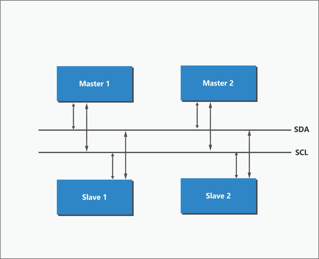
I2C (Inter-Integrated Circuit)
- Synchronous, two-wire protocol: SDA (data), SCL (clock).
- Supports multiple masters and slaves on a single bus.
- Slower than SPI but simpler wiring.
- Uses device addressing for communication.
- Ideal for short-distance, low-speed sensor networks.
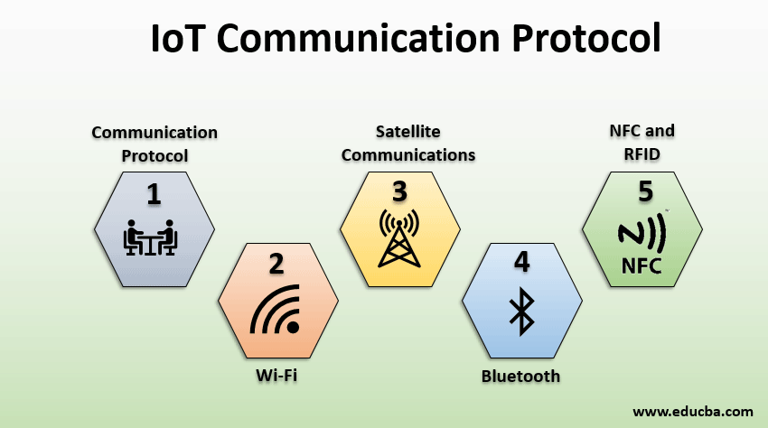
IoT Communication
IoT communication enables devices to connect and share data over the internet. It involves wired (Ethernet, RS485) and wireless (Wi-Fi, Bluetooth, Zigbee, LoRa, NB-IoT) technologies. Protocols like MQTT, HTTP, and CoAP manage data exchange efficiently. Devices use sensors to collect data and send it to cloud or edge servers.
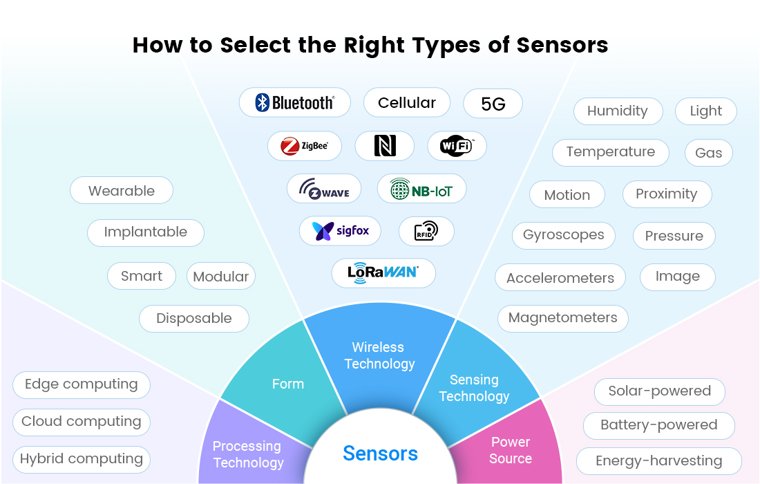
IoT Sensors
ESP-NOW Communication Setup and Working
For this assignment, I used two ESP32/XIAO ESP32 boards to establish wireless communication using the ESP-NOW protocol. One board acts as the Transmitter (Master) and the other acts as the Receiver (Slave). The transmitter reads the button input and sends the data wirelessly to the receiver. Based on the received data, the receiver controls multiple LEDs.
ESP-NOW
ESP-NOW is a wireless communication protocol developed by Espressif Systems for ESP32 and ESP8266 boards. It allows direct device-to-device communication without using a Wi-Fi router or internet connection.
Features of ESP-NOW
System Architecture
Transmitter (Master)
Receiver (Slave)
Hardware Used
Transmitter code
#include <esp_now.h>
#include <WiFi.h>

typedef struct {
  bool buttonPressed;
} joystickData;

joystickData dataToSend;

uint8_t receiverMAC[] = {0x18, 0x8B, 0x0E, 0x93, 0xA3, 0xC4};  // Replace with receiver MAC

const int swPin = 2;  // Joystick button pin

void onSent(const uint8_t *mac_addr, esp_now_send_status_t status) {
  Serial.print("Send Status: ");
  Serial.println(status == ESP_NOW_SEND_SUCCESS ? "Success" : "Fail");
}

void setup() {
  Serial.begin(115200);
  WiFi.mode(WIFI_STA);

  pinMode(swPin, INPUT_PULLUP);  // Joystick button (active LOW)

  if (esp_now_init() != ESP_OK) {
    Serial.println("ESP-NOW init failed!");
    return;
  }

  esp_now_register_send_cb(onSent);

  esp_now_peer_info_t peerInfo = {};
  memcpy(peerInfo.peer_addr, receiverMAC, 6);
  peerInfo.channel = 0;
  peerInfo.encrypt = false;

  if (esp_now_add_peer(&peerInfo) != ESP_OK) {
    Serial.println("Failed to add peer");
    return;
  }
}

void loop() {
  // Button pressed = LOW → true
  dataToSend.buttonPressed = digitalRead(swPin) == LOW;

  Serial.print("Button: ");
  Serial.println(dataToSend.buttonPressed ? "PRESSED" : "NOT PRESSED");

  esp_now_send(receiverMAC, (uint8_t *)&dataToSend, sizeof(dataToSend));
  delay(200);
}
- esp_now.h is for ESP-NOW communication and WiFi.h is needed because ESP-NOW needs WiFi in station (STA) mode.
- uint8_t receiverMAC[] = {0x18, 0x8B, 0x0E, 0x93, 0xA3, 0xC4}; - This is the MAC address of the receiver ESP32. We should replace it with our receiver board’s MAC.
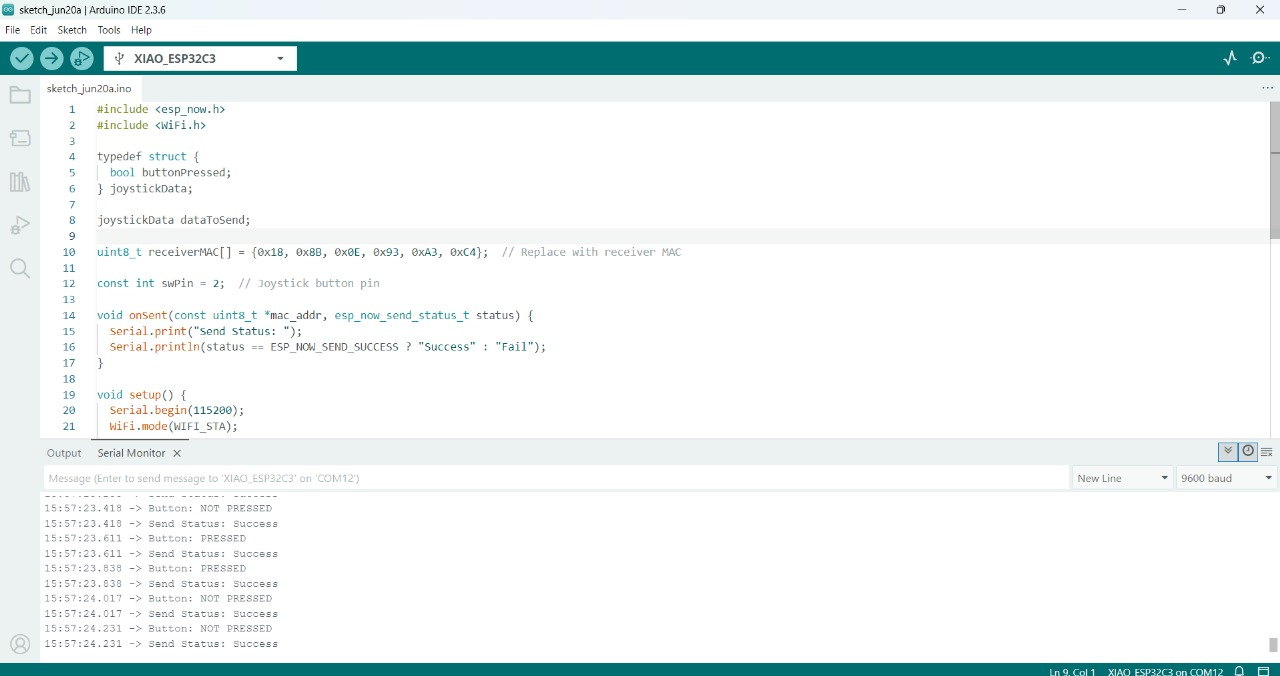
I upload this code to the Master microcontroller and check the serial monitor as well
Then write down the Recdeiver code for the output
Receiver code
#include <esp_now.h>
#include <WiFi.h>

typedef struct {
  bool buttonPressed;
} joystickData;

joystickData receivedData;

// List of LED pins
const int ledPins[] = {2,3,4, 5, 6,7,8,9,10, 20,21};  // GPIO4 = D2, GPIO5 = D3, GPIO10 = D10
const int numLeds = sizeof(ledPins) / sizeof(ledPins[0]);

void onReceive(const esp_now_recv_info_t *info, const uint8_t *incomingData, int len) {
  Serial.println("Data received");

  memcpy(&receivedData, incomingData, sizeof(receivedData));

  Serial.print("Button Status: ");
  Serial.println(receivedData.buttonPressed ? "PRESSED" : "NOT PRESSED");

  for (int i = 0; i < numLeds; i++) {
    digitalWrite(ledPins[i], receivedData.buttonPressed ? HIGH : LOW);
  }

  Serial.print("LEDs: ");
  Serial.println(receivedData.buttonPressed ? "ON" : "OFF");
}

void setup() {
  Serial.begin(115200);
  delay(1000);
  Serial.println("Receiver with multiple LEDs starting...");

  // Set all LED pins as output
  for (int i = 0; i < numLeds; i++) {
    pinMode(ledPins[i], OUTPUT);
    digitalWrite(ledPins[i], LOW);
  }

  WiFi.mode(WIFI_STA);

  if (esp_now_init() != ESP_OK) {
    Serial.println("ESP-NOW init failed!");
    return;
  }

  esp_now_register_recv_cb(onReceive);
  Serial.println("ESP-NOW Ready. Waiting for joystick button...");
}

void loop() {
  // Nothing here
}
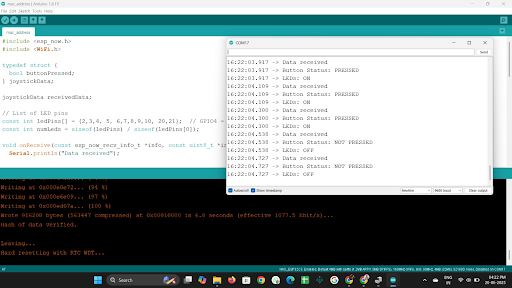
After uploading it I check the status of Slave microcontroller
Purpose of Libraries
ESP-NOW Setup Procedure
ESP-NOW requires the ESP32 to work in Station (STA) mode for peer-to-peer communication.
if (esp_now_init() != ESP_OK) {
  Serial.println("ESP-NOW init failed!");
  return;
}
This initializes the ESP-NOW protocol. If initialization fails, communication cannot happen.
uint8_t receiverMAC[] = {0x18, 0x8B, 0x0E, 0x93, 0xA3, 0xC4};
Every ESP32 board has a unique MAC address. The transmitter uses the receiver MAC address to identify where the data should be sent.
esp_now_peer_info_t peerInfo = {};
memcpy(peerInfo.peer_addr, receiverMAC, 6);
peerInfo.channel = 0;
peerInfo.encrypt = false;
esp_now_add_peer(&peerInfo);
typedef struct {
  bool buttonPressed;
} joystickData;
This structure is used to package and transfer data wirelessly between ESP32 boards. The structure stores the button status as True or False only.
esp_now_send(receiverMAC, (uint8_t *)&dataToSend, sizeof(dataToSend));
esp_now_register_send_cb(onSent);This callback function checks whether the data was sent successfully.
esp_now_register_recv_cb(onReceive);
This callback function automatically runs whenever data is received.
Communication Flow
I selected ESP-NOW because it provides fast wireless communication between ESP32 boards without needing internet connectivity or an external router.
Testing
The transmitter ESP32 successfully detected the button press and sent the data wirelessly using ESP-NOW.
The receiver ESP32 received the transmitted data correctly through MAC address-based communication.
Based on the received button status, all connected LEDs turned ON and OFF successfully.
Conclusion
Learning outcomes
- Understood the concept of master-slave communication using ESP-NOW protocol with ESP32 boards.
- Successfully implemented the transmitter (master) to read a button press and send data wirelessly.
- Practiced struct-based data transfer over ESP-NOW, ensuring type-safe communication.
- Gained hands-on experience in wireless device-to-device communication without needing Wi-Fi networks.