Output Devices
Overview of week 10
Group Assignment
- Measure the power consumption of an output device.
Individual Assignment
- Add an output device to a microcontroller board you've designed and program it to do something.
Group Assignment :
Selected a DC motor as the output device and used a potentiometer to vary its load.
Connected the motor to a 5V power supply and monitored real-time voltage and current values
Applied the formula 𝑃 = 𝑉×𝐼 to calculate power consumption
Individual Assignment :
What is Output Devices ?
Output devices in electronics are components that convert electrical signals or digital data into a form that humans can perceive or use. They play a crucial role in displaying, producing sound, or transferring data from a system to the external environment. These devices can convert data into visual, auditory, or physical forms. The primary function is to present the results of data processing to users. They are essential for interaction with the system, providing feedback or information in real-time. Output devices can vary in size, function, and technology used. Their effectiveness directly influences user experience and system usability.
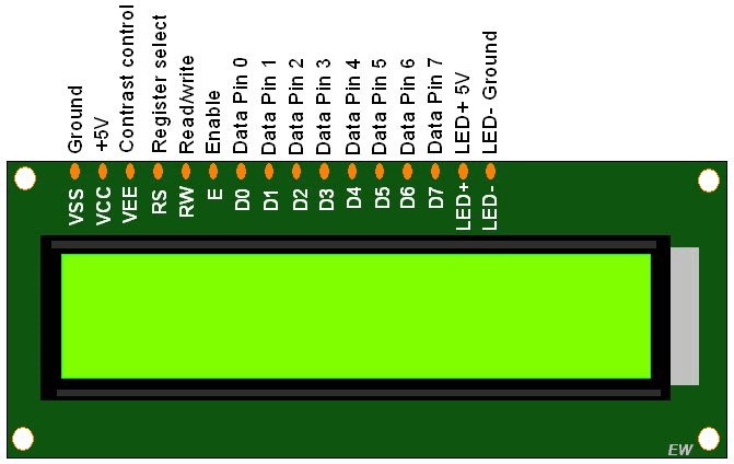
1.LCD/LED Displays
Character LCDs (e.g., 16x2 LCD) – Used to display simple text information.
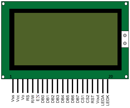
Graphic LCDs – Can display graphics and more complex visuals.
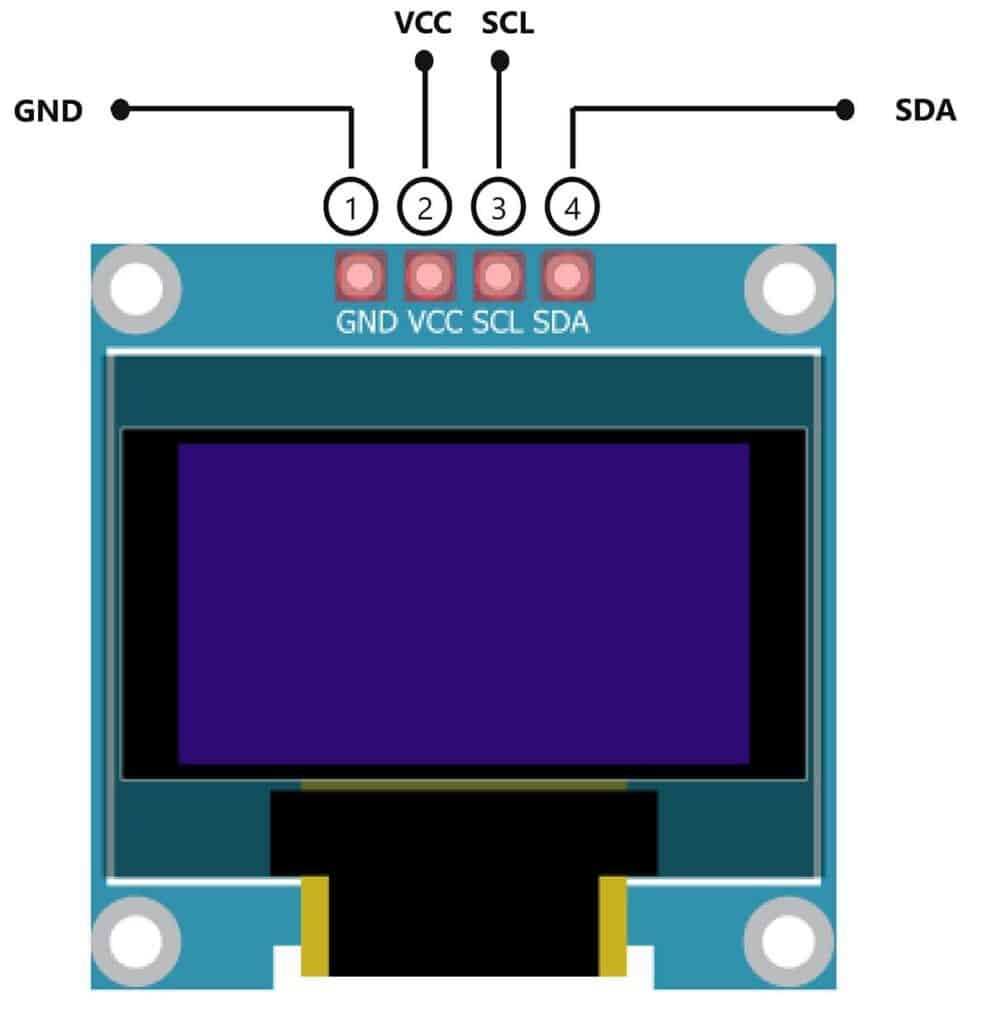
OLED Displays – Low-power, high-contrast displays used for text and graphics.
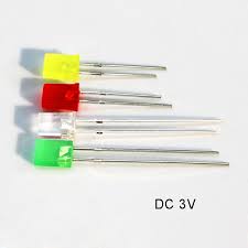
2.LEDs (Light Emitting Diodes)
Individual LEDs – Simple and low-cost output devices often used to indicate status or errors.
RGB LEDs – Multi-colored LEDs can indicate different status conditions using different colors.
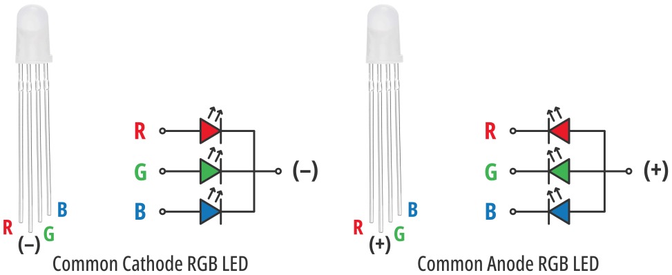
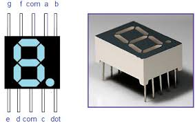
7-segment displays – Used to show numerical digits, such as on clocks, thermometers, or counters.
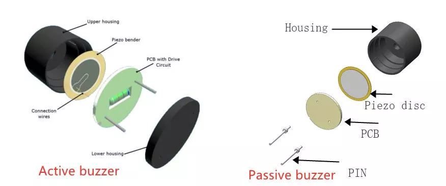
3.Buzzers
Passive Buzzer – Produce a beep or tone when a signal is applied. Commonly used for alerts or alarms.
Active Buzzer – Similar to passive buzzers but generate sound on their own without an external signal.
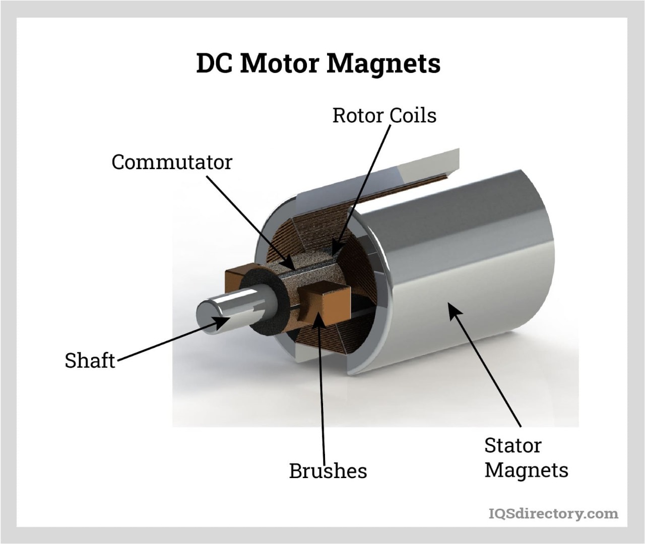
4.Motors and Actuators
DC Motors – Common in robotics and automation to perform mechanical tasks.
Stepper Motors – Provide precise control of movement, often used in robotics and 3D printing.
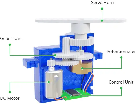
Servos – Used for precise control of angular position, often used in robotic arms or camera gimbals.
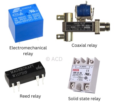
5.Relays
Relays are electrically operated switches that can control higher power devices (like turning on a light or controlling appliances) from a low power embedded system.
Prepare the PCB
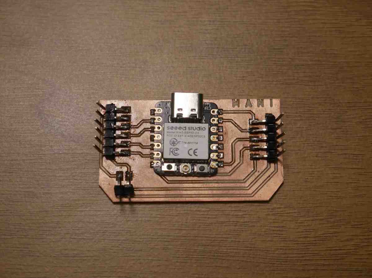
I used the XIAO RP 2040 microcontroller for my Output devices assignement.
I designed the layout diagram by using the Kicad software,
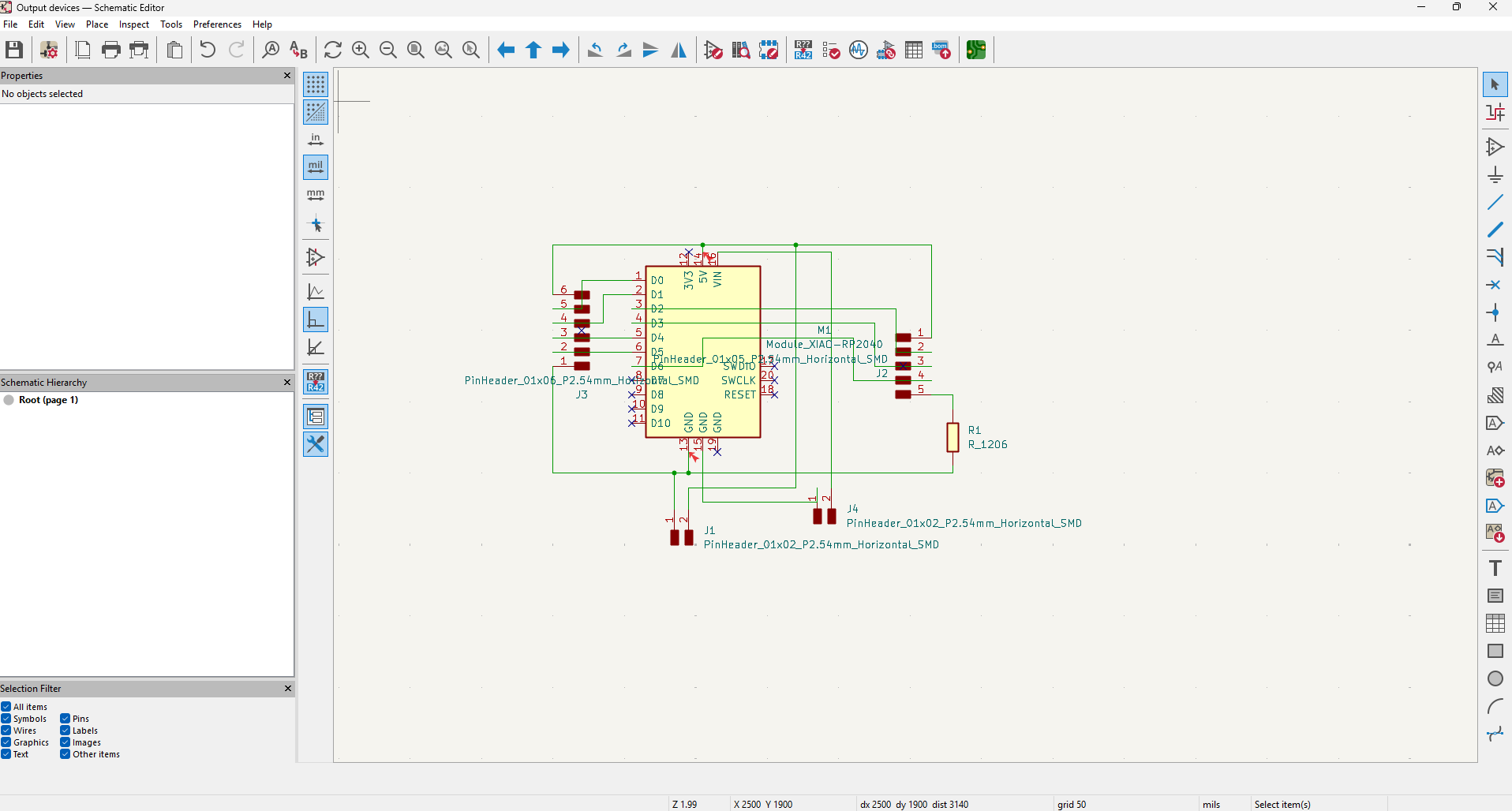
After did the Symbol editing then I update it into the PCB editor
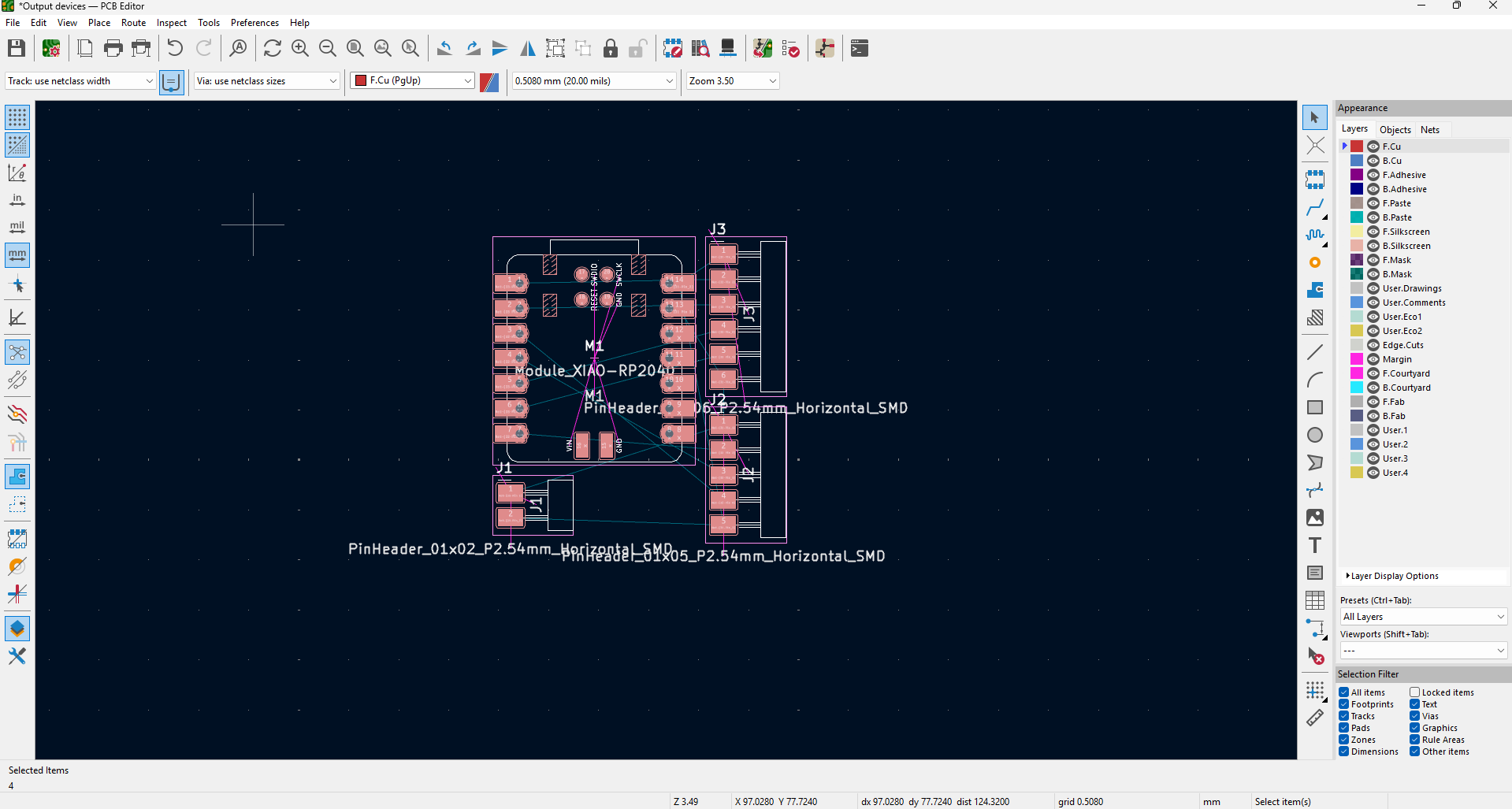
Then I rearrange it properly then add the trace connections, then I took out it for PCB milling
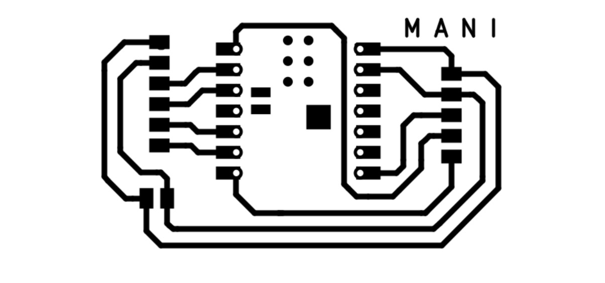
Then by using the MODS I create the tool path and did the milling process with this board
PCB Production
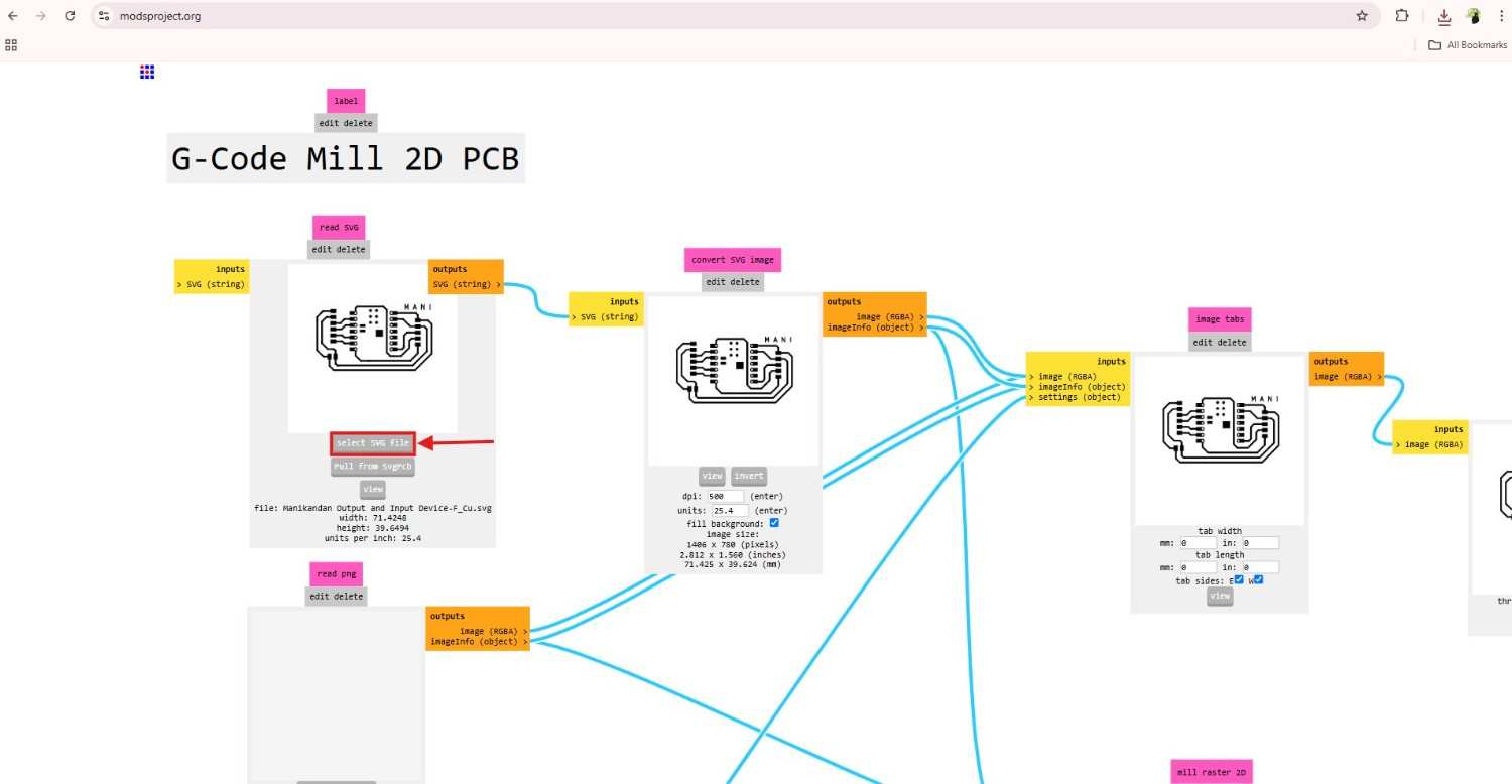
I used the MODS for the gcode generation, MODs is very easy to operate and change our parameters more often how we want with particular limitation, it is widely used by our Fab Academy students
After import it I set up the required parameters and take out the perfect gcode for my PCB milling
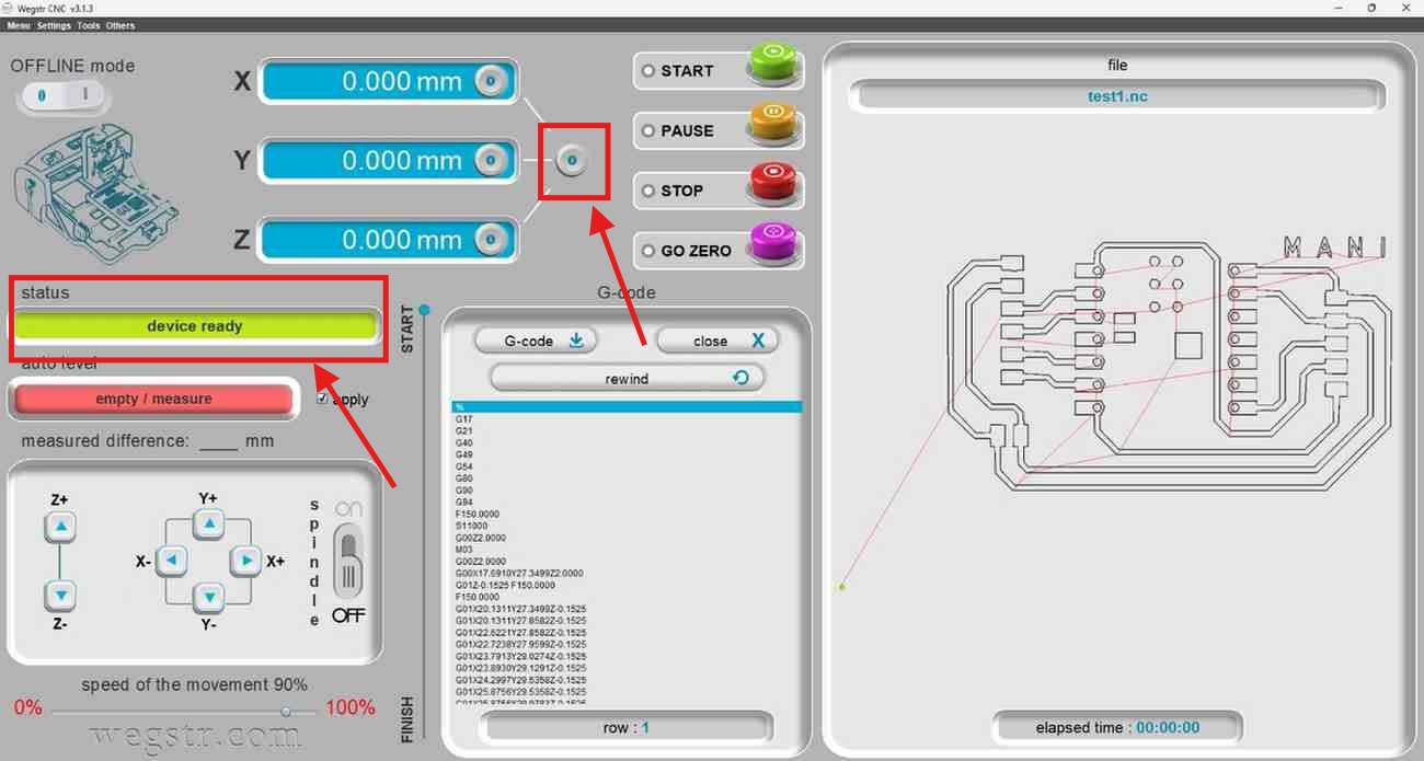
By using the Wegstr software I control the Wegstr PCB milling machine, I setting the milling tool in the spindle and adjust the tool position where I want to cut out my board.
After the PCB milling process I check the board with Multimeter by continuity test and solder the components with the board
If you want to know more about this board you can see my Electronic Production assignment.
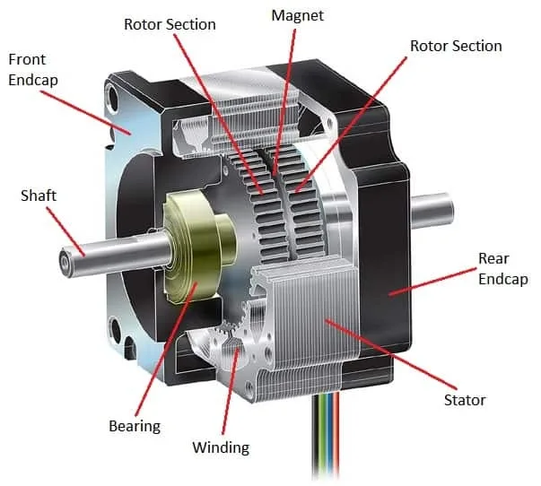
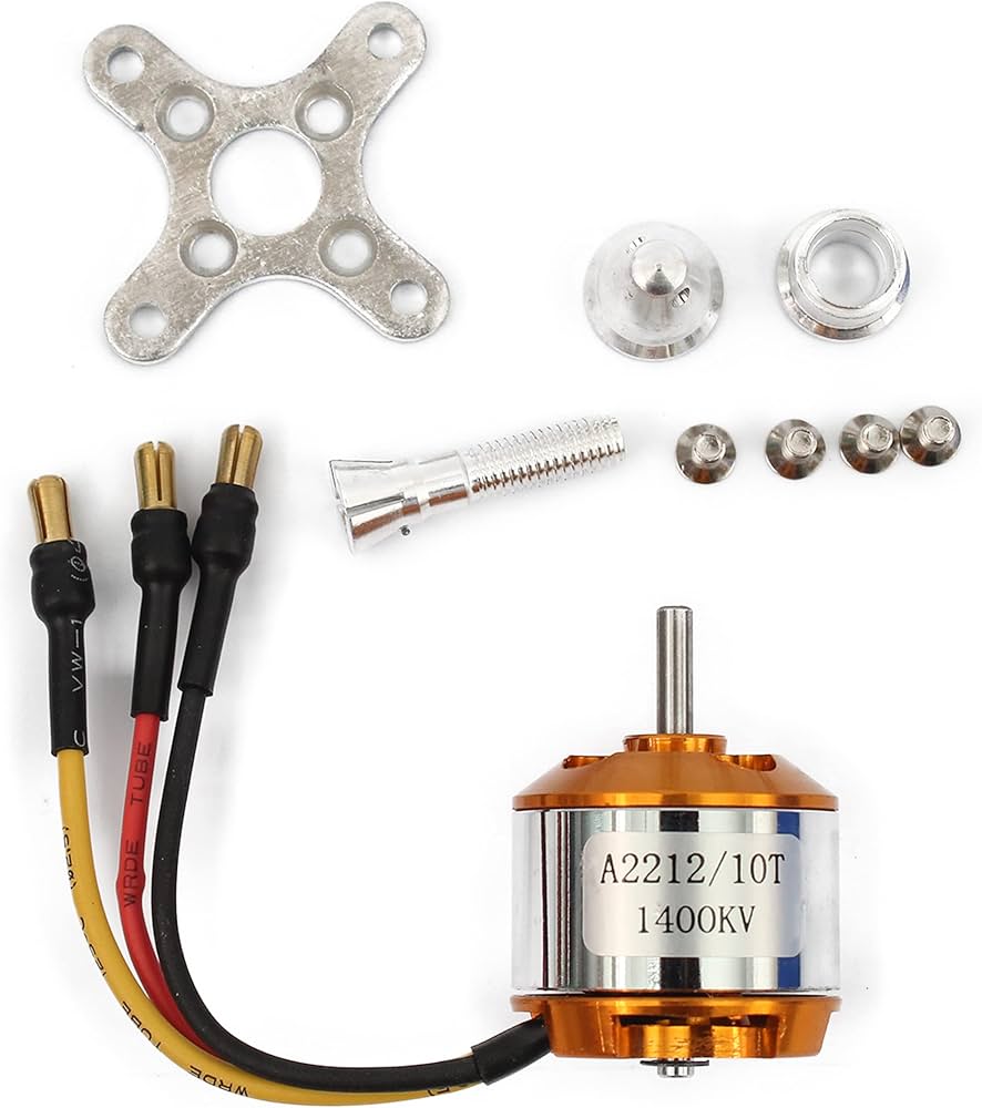
Bldc Motor
- BLDC motors are brushless DC motors that use electronic commutation rather than mechanical brushes.
- They require electronic controllers (ESCs) to manage the timing of power delivery.
- Depending on the design, they can operate sensorless or with Hall-effect sensors for precise rotor position detection.
- Their efficiency and durability make them ideal for applications like drones, electric vehicles, and industrial machinery.
Here I add some reference video of hw BLDC motor works - Link
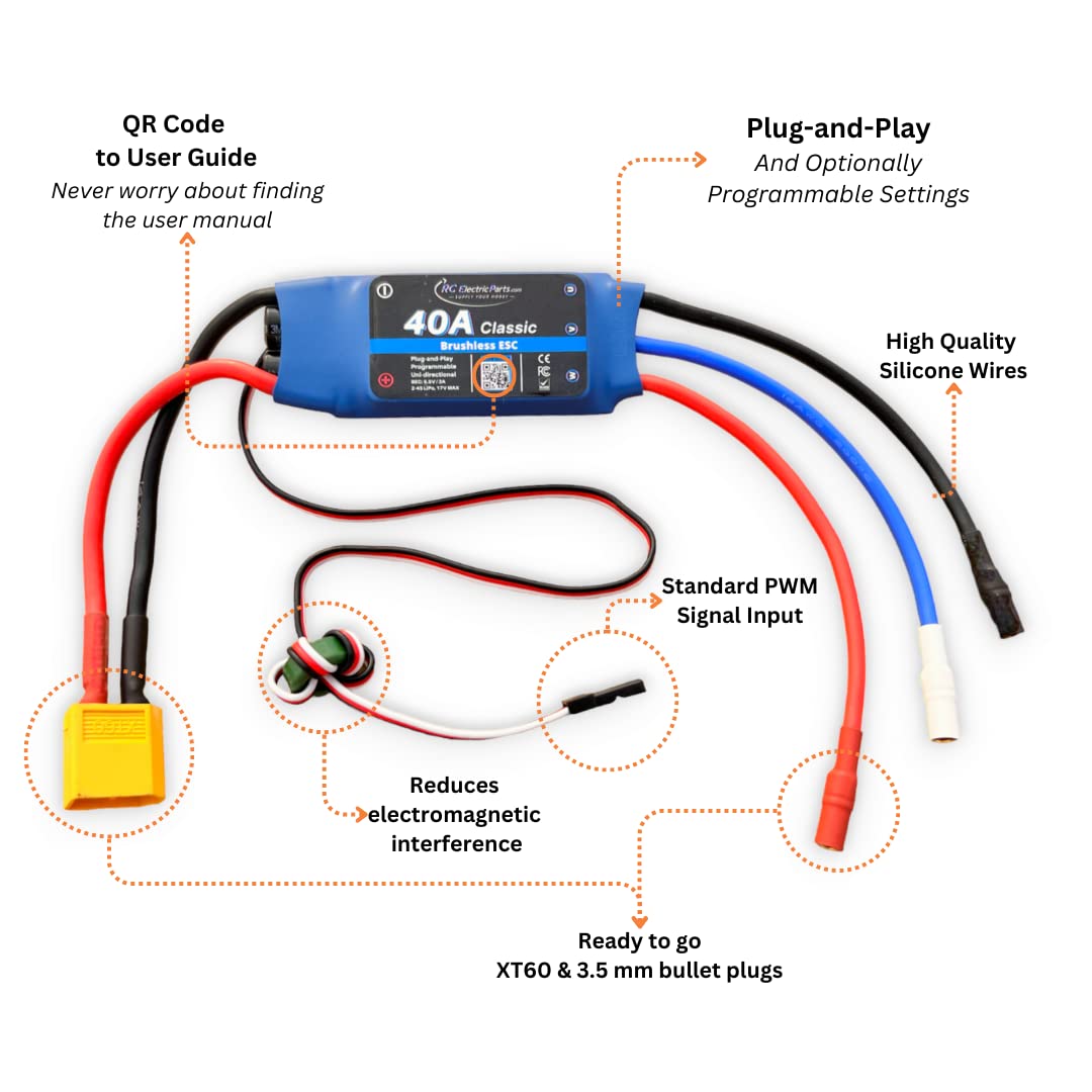
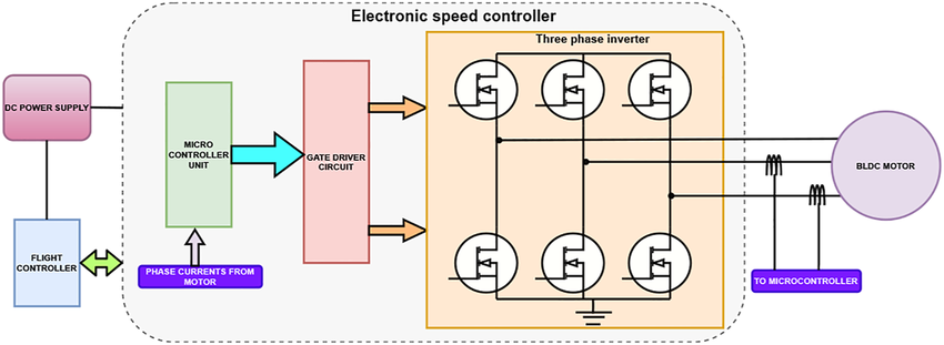
Electronic Speed Controller (ESC)
- An Electronic Speed Controller (ESC) regulates the speed, direction, and braking of a BLDC motor.
- It converts DC power into three-phase AC signals to drive the motor efficiently.
- They use PWM signals from a microcontroller or receiver to adjust motor speed.
Programming
#include <ESP32Servo.h>

#define ESC1_PIN D4  // Left motor
#define ESC2_PIN D5  // Right motor

#define JOY_X_PIN A1
#define JOY_Y_PIN A2

Servo esc1;
Servo esc2;

void setup() {
  Serial.begin(115200);

  pinMode(A1,INPUT);
  pinMode(A2,INPUT);
  pinMode(ESC1_PIN,OUTPUT);
  pinMode(ESC2_PIN,OUTPUT);
  esc1.attach(ESC1_PIN);
  esc2.attach(ESC2_PIN);

  esc1.writeMicroseconds(1000);
  esc2.writeMicroseconds(1000);
  delay(2000);  // Let ESCs initialize


}

void loop() {
  int xValue = analogRead(JOY_X_PIN);
  int yValue = analogRead(JOY_Y_PIN);
delay(1000);
Serial.println("start");
  Serial.print("X: ");
  Serial.println(xValue);
  Serial.print(" | Y: ");
  Serial.println(yValue);


  int pwmLeft = 1000;
  int pwmRight =1000;

  // Forward motion (both motors)
  if (yValue >3800) {
    int pwm = map(yValue, 3800,4095, 1000, 2000);
    pwmLeft = pwm;
    //analogWrite(ESC1_PIN,pwm);
   // analogWrite(ESC2_PIN,pwm);

    pwmRight = pwm;
    Serial.println("Moving Forward");


  // Backward motion (optional)
  /*else if (yValue < 400) {
    int pwm = map(yValue, 0, 400, 0, 1000);
    pwmLeft = pwm;
    pwmRight = pwm;
    Serial.println("Moving Backward");
  }
   */
  // Turning left or right by adjusting individual motor speeds
  }else if (xValue < 3000) {
    int turnPWM = map(xValue,  3000, 0,1000, 2000);
    pwmRight = turnPWM;  // Slow down right motor
    Serial.println("Turning Left");
  } else if (xValue > 3800) {
    int turnPWM = map(xValue, 3800, 4095, 1000, 2000);
    pwmLeft = turnPWM;  // Slow down left motor
    Serial.println("Turning Right");
  } else
  {
     esc1.writeMicroseconds(1000);
     esc2.writeMicroseconds(1000);
     Serial.println("Moving ");
  //delay(2000);
  }


 esc1.writeMicroseconds(pwmLeft);
  esc2.writeMicroseconds(pwmRight);

  delay(1000);
}
- I connected the joystick analog pins with microcontroller XIAO ESP32C3 board A1 and A2, and also connected the 5V and GND with the Microcontroller.
- After that, I take 2 BLDC motor, attached with 2 ESC for controlling it. In the ESC, there is three pins, the two is 5V and GND and the other pin is output digital pin I connected with microcontroller at D4 and D5.
- I set the A1 and A2 as input and ESC pins as output, then write the analog read for Joystick X and Y direction operation
- For visualize the serial monitor I set the serial print ln, and add the references for how it will need to show
- I mapped the joystick value depending upon the X and Y high and low values, at first I normaly check the joystick to how much it could take the value, after figure outing that I randomly set the Joystick potentiometer position.
Testing
I tested the BLDC motor with my PCB board, it works good
Though the delay has some little bit occur in my code when I try this one, so I will change it
For checking more output device unfortunately my board got damage so I can’t go furhter with this board so I use my Final Project Board to continue this assignment.
Conclusion
Learning outcomes
- I learnt about some of the output devices functionality and its working principle, how we efficiently used it for our required use cases.
- For this assignment I uses the 2 BLDC Motor with ESC, now I know about how we can operate the motor with joystick module
- I learnt the Joystick mapping for the output device control
- For my final project I will use the 6 BLDC motor so I first check with these 2 motors for coding initiation.
Challenges
At first I am lacking in joystick mapping so I use the Chatgpt to understand the mapping properly for output control
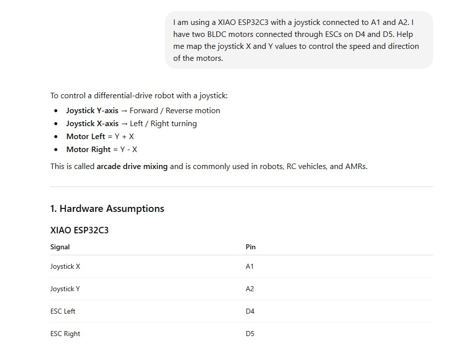
My board for this assignment is broken, I solder the normal head pins but its came out wiht the copper coating so I can’t use it further use. So I should desoldering the XIAO ESP32C3 board from the PCB board