Computer Controlled Machining

Overview of week 7
Group Assignment
- Complete our lab's safety training
- Test runout, alignment, fixturing, speeds, feeds, materials and toolpaths for our machine
Individual Assignment
• Make (design+mill+assemble) something big
extra credit: don't use fasteners or glue
extra credit: include curved surfaces
Group Assignment :
Individual Assignment :
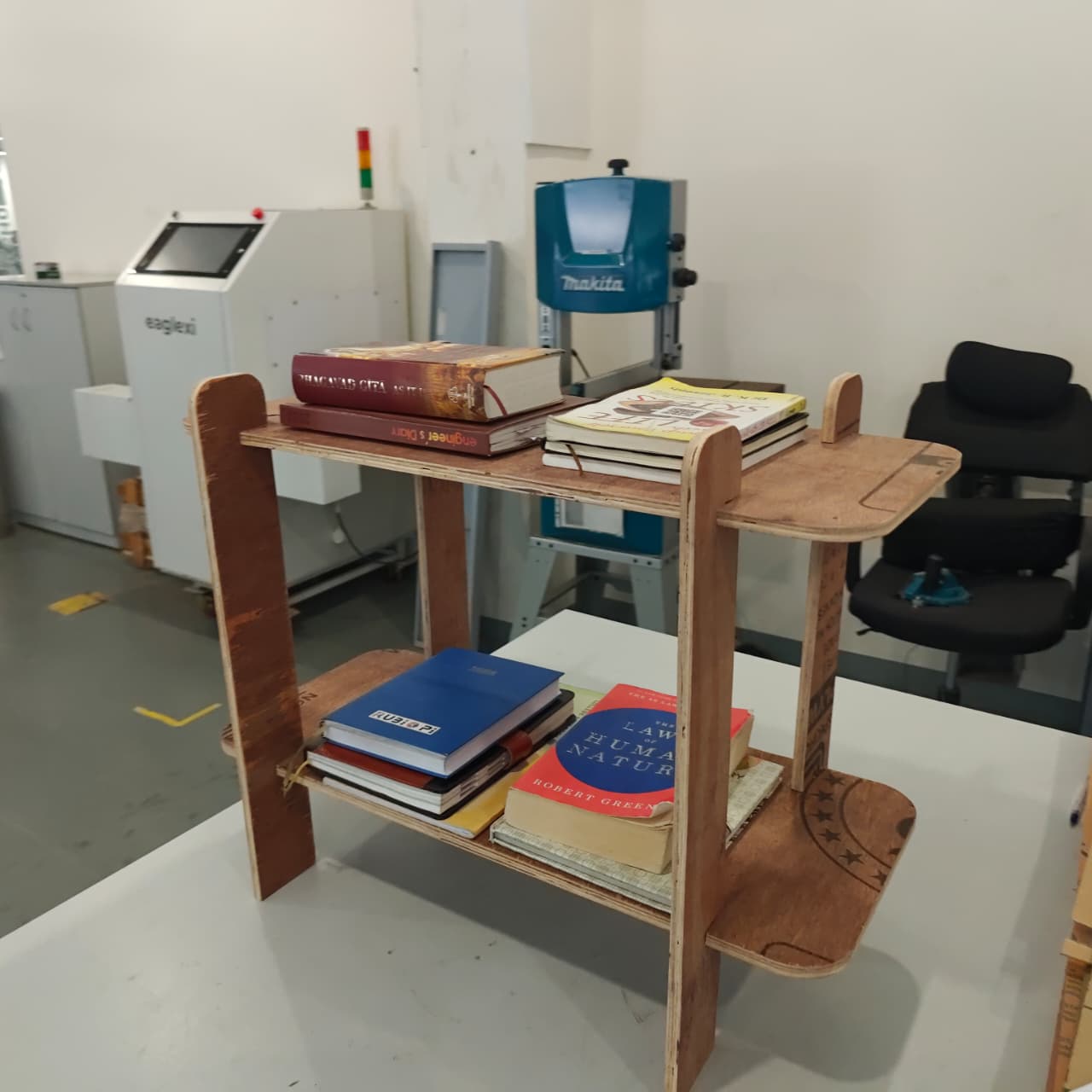
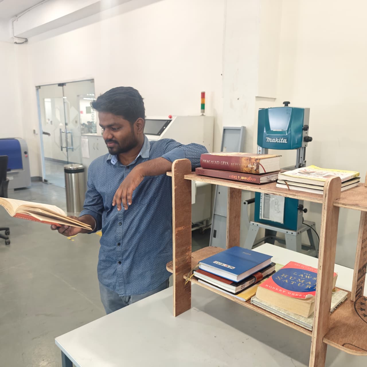
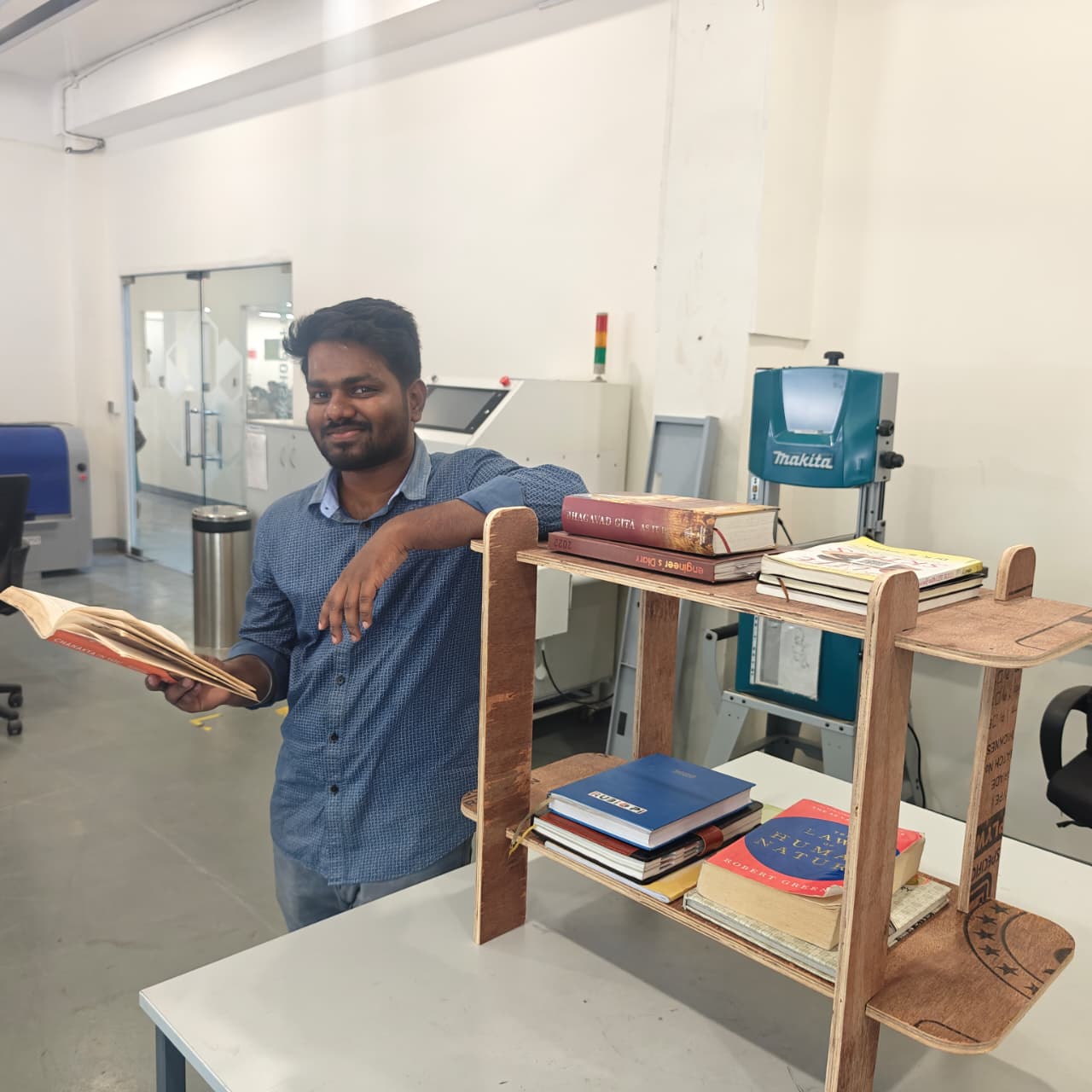
Hero shot
CNC Wood Router
A CNC wood router is a computer-controlled cutting machine used for carving, engraving, and shaping wood with high precision. It automates the routing process, reducing manual labor and increasing accuracy. CNC routers are versatile, capable of working with hardwood, plywood, and MDF. They are ideal for furniture making, sign making, decorative woodwork, and prototyping. Key features include high precision, repeatability, and speed in production. When choosing a CNC wood router, consider factors like work area size, spindle power, software compatibility, and build quality. These machines are essential for mass production with consistent quality.
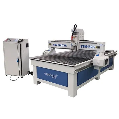
In our lab we have a CNC Wood Router STM1325
Specification
- Model - STM1325
- Working Size - 1300mm*2500mm*200mm
- Body structure - Steel tubes X, Y Structure rack and pinion drive Z Structure Ball Screw/option gear wheel
- X, Y Resolution - <0.01mm 5. Max Moving Speed - 32000mm/min6. Max Engraving Speed - 20000mm/min
- XYZ travelling positioning accuracy - 0.03/300mm
- XYZ repositioning accuracy - 0.03mm
- Spindle power - 3kw/4.5kw/5.5KW
- Spindle Speed - 24,000 rpm
- Table style - T-slot table
Fusion360
Fusion 360 is a cloud-based 3D CAD, CAM, and CAE software developed by Autodesk. It integrates design, simulation, rendering, and manufacturing tools in a single platform. Fusion 360 is widely used for product design, mechanical engineering, and CNC machining. It supports parametric, direct, freeform, and surface modeling. The software also includes simulation and generative design features for optimizing parts. Its built-in CAM tools enable CNC programming for milling, turning, and laser cutting. Fusion 360 is popular for prototyping, reverse engineering, and collaborative design.
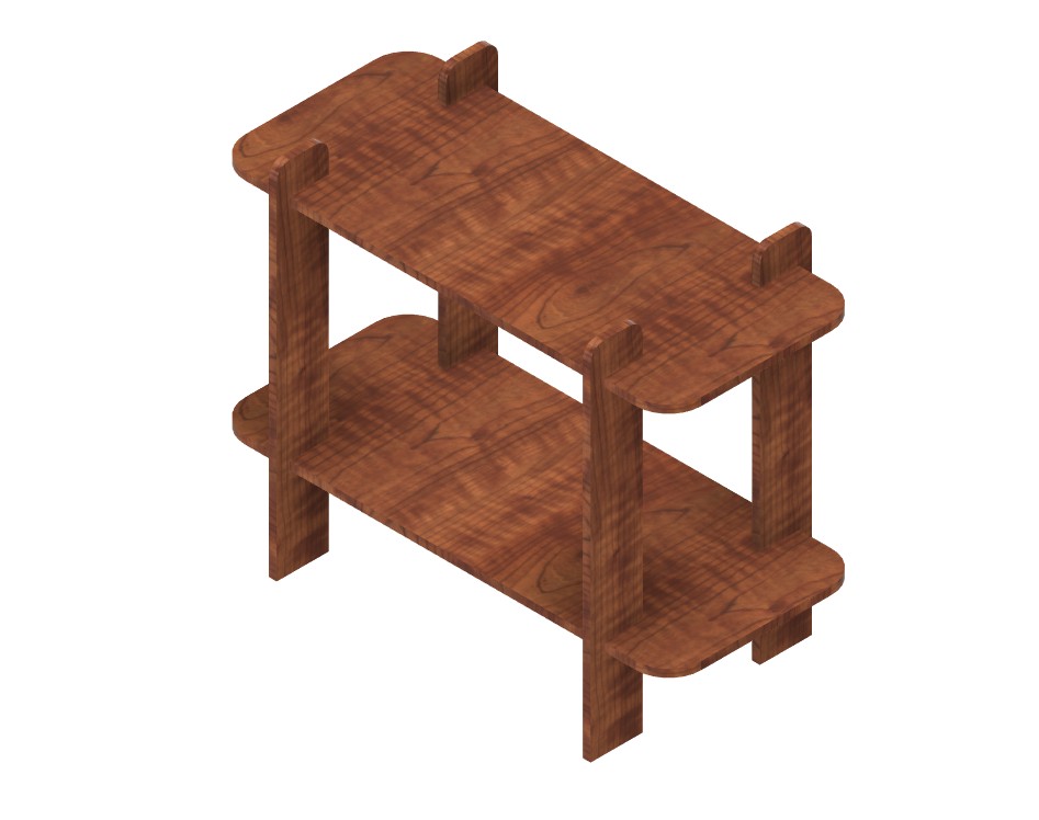
I have planned to design and cut a bookshelf table for this week’s assignment. I am starting with Fusion 360 to design the bookshelf table.
I conducted a Google search for bookshelf references and found this simple yet elegant design.

First, I sketched the rough dimensions on paper. Then, I proceeded to draw the base and set it according to the defined parameters for parametric modeling.
The shelf was designed using a parametric modeling approach to simplify future modifications and improve design flexibility. At the beginning of the design process, the material thickness was defined as a parameter with a value of 12 mm.
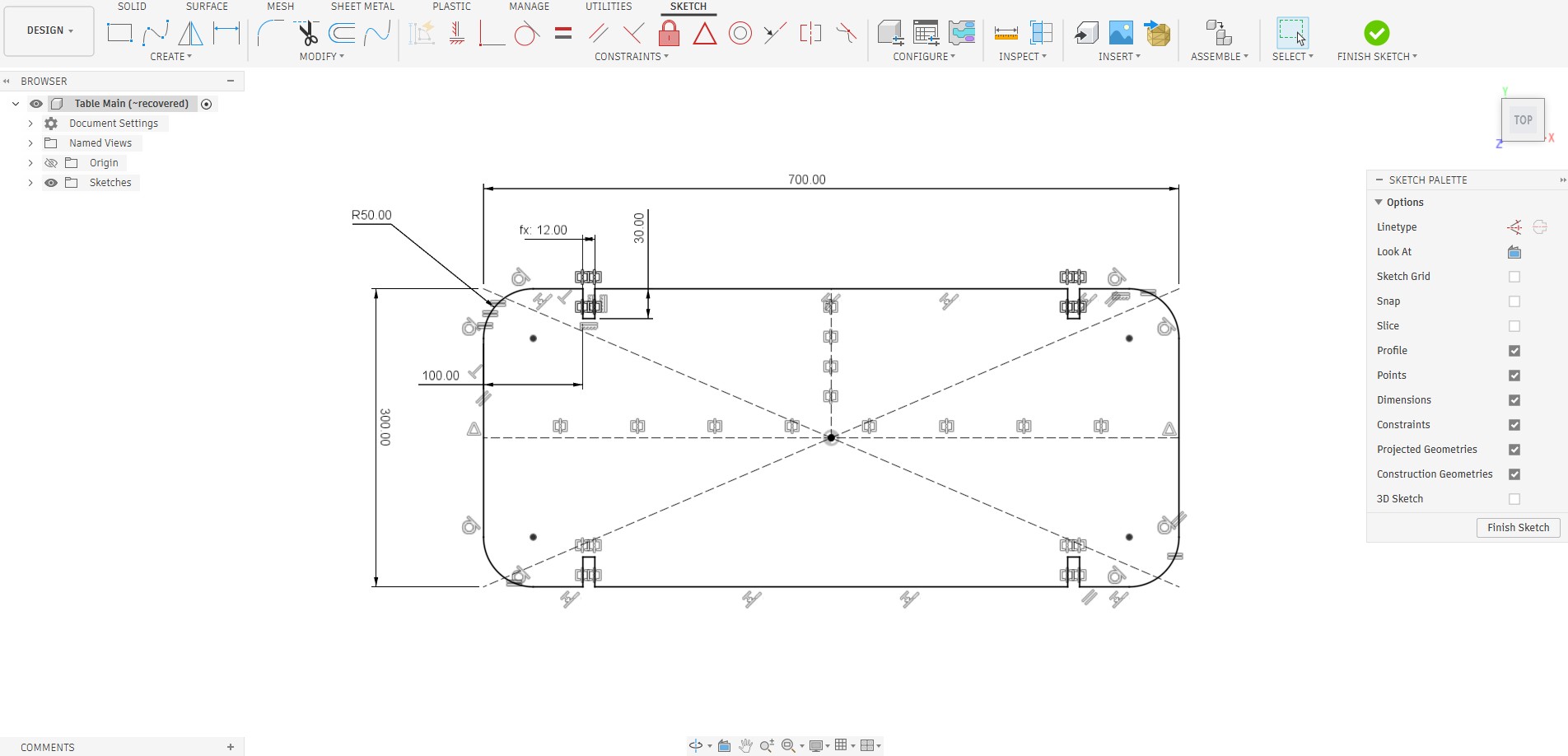
Using parameterized dimensions allows the design to be updated easily in the future. If a different material thickness is required, only the parameter value needs to be modified, and all dependent features will automatically update accordingly.
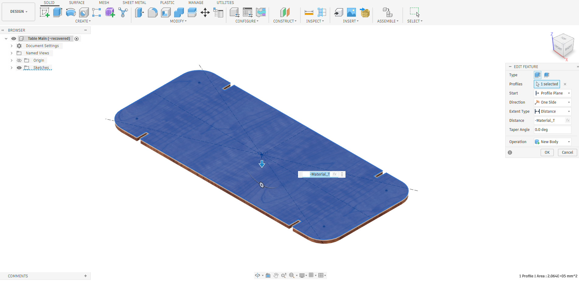
After defining the material thickness parameter, the overall length and width of the shelf were created according to the planned dimensions. The base profile was then extruded using the predefined material thickness value to generate the main shelf structure.
The next step involved designing the leg components that support the shelf structure. To ensure proper assembly, a clearance of 0.5 mm was incorporated into the mating features.
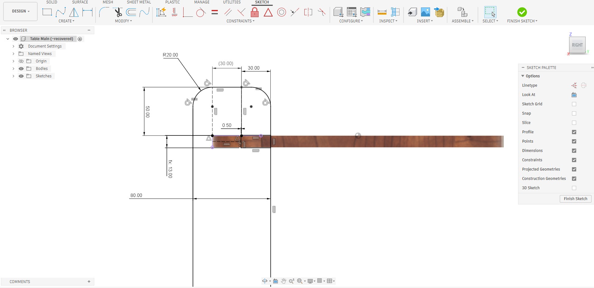
The joints were designed to improve structural rigidity and provide a secure connection between the assembled parts.
Once the leg geometry and joint features were completed, the components were extruded using the same material thickness parameter to maintain consistency throughout the design.
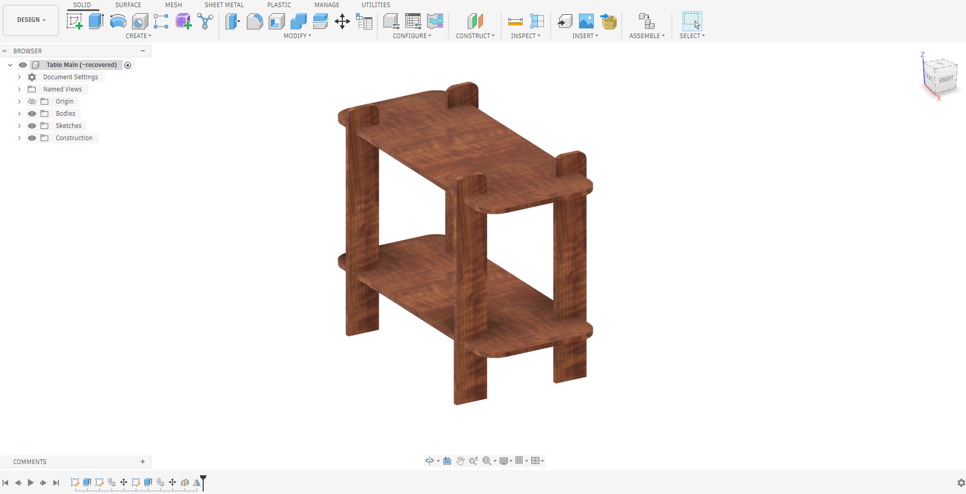
After verifying the dimensions and assembly features, the final design was prepared for digital fabrication. The required sketches and profiles were exported in DXF format, which would be used in the subsequent CAM and machining operations.
ArtCAM
ArtCAM was a CAD/CAM software developed by Delcam (later acquired by Autodesk) for designing and manufacturing artistic reliefs. It specialized in 2D and 3D modeling, mainly used for woodworking, sign making, and jewelry design. ArtCAM combined vector design tools with powerful sculpting and machining capabilities. It allowed users to create intricate designs and generate toolpaths for CNC machines.
Here we can check the Autodesk's Artcam software - Artcam
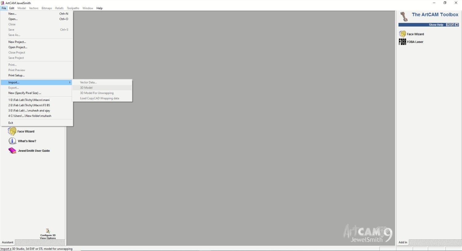
Import the DXF file into it, and set up the orgin for the required space where your desing will be in frame, after setup everything click apply and paste.
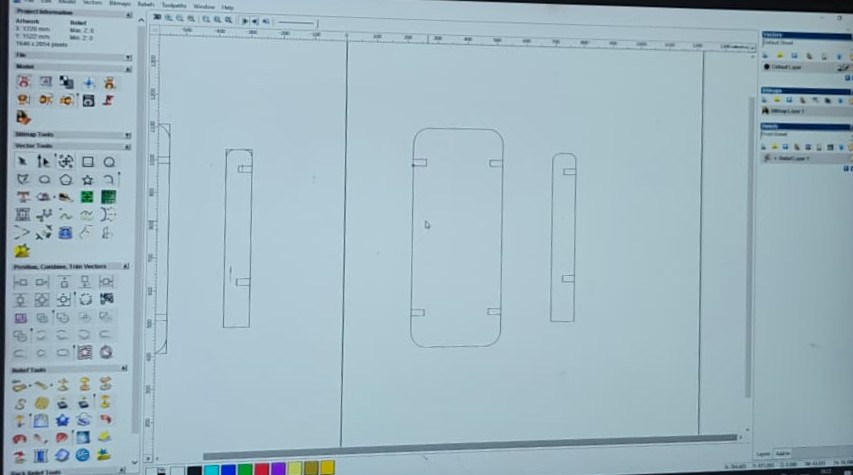
After setting it select the tool parameter according to our design, in my case i selected the End mill 6 mm tool for the milling and set the thickness 12mm
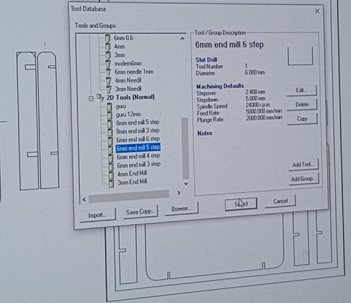
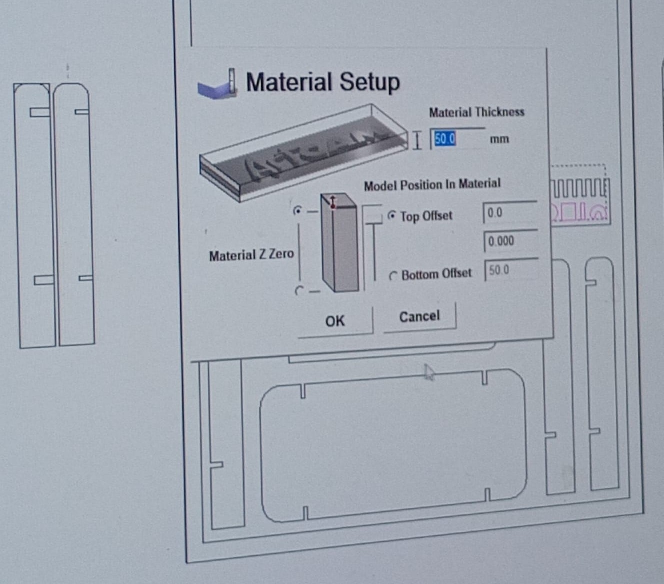
After setting the tool, I give the tool path
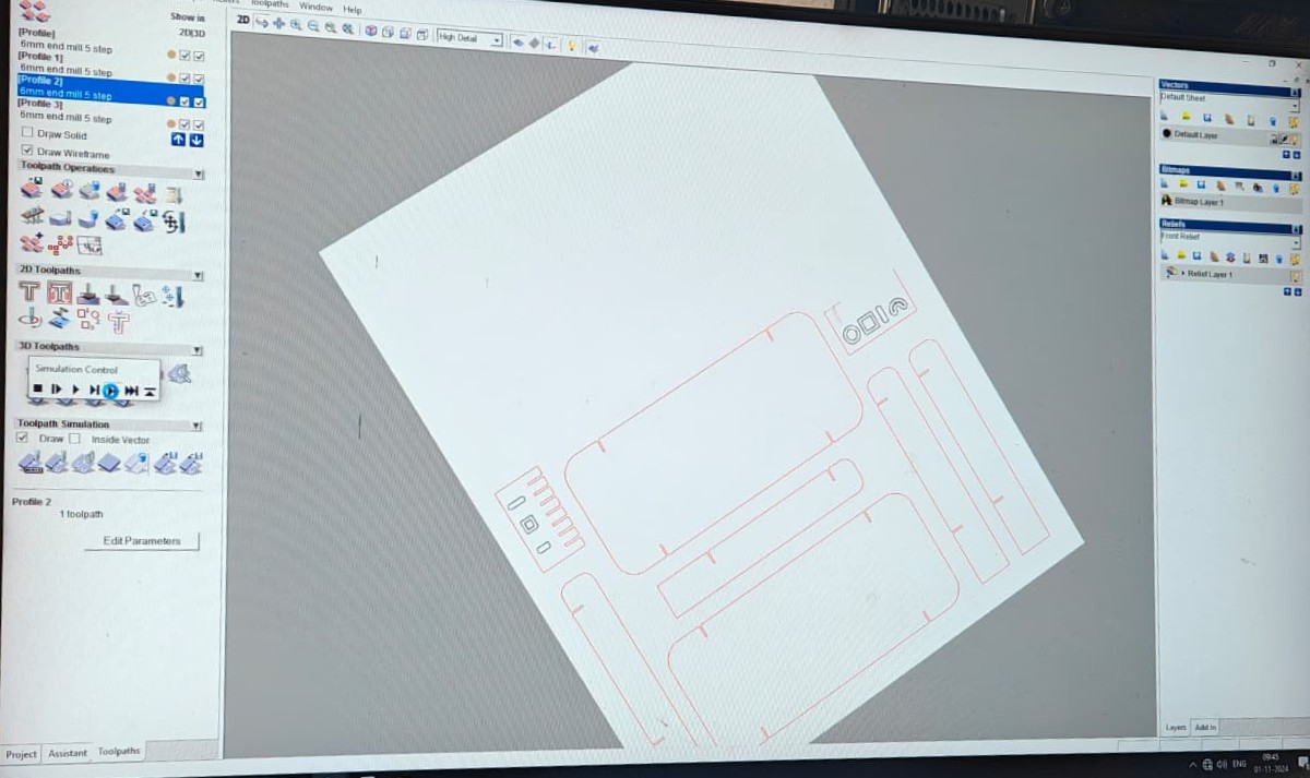
Then converted it into the G-code fot the machining operation.
Safety Precautions
Before operating the CNC router, we followed the lab safety procedures:
Material Used
I used plywood as the machining material. Plywood is widely used in CNC routing because it is economical, readily available, dimensionally stable, and easy to machine. The material thickness was selected according to the design requirements and tool availability.
Why Plywood?
CNC Milling
After the software part I straightly jump into the CNC router, it has very essential part to us to operate the machine carefully.
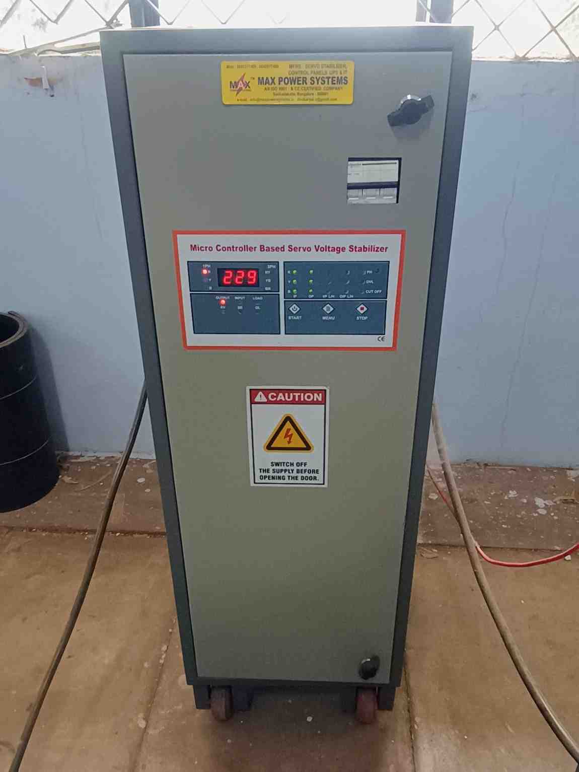
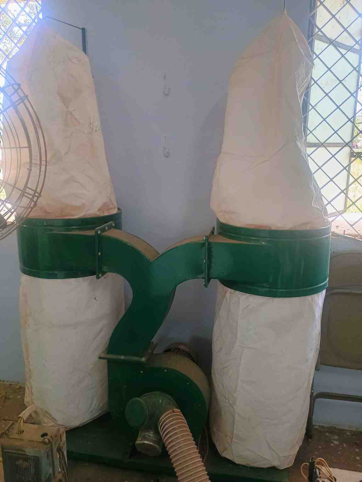
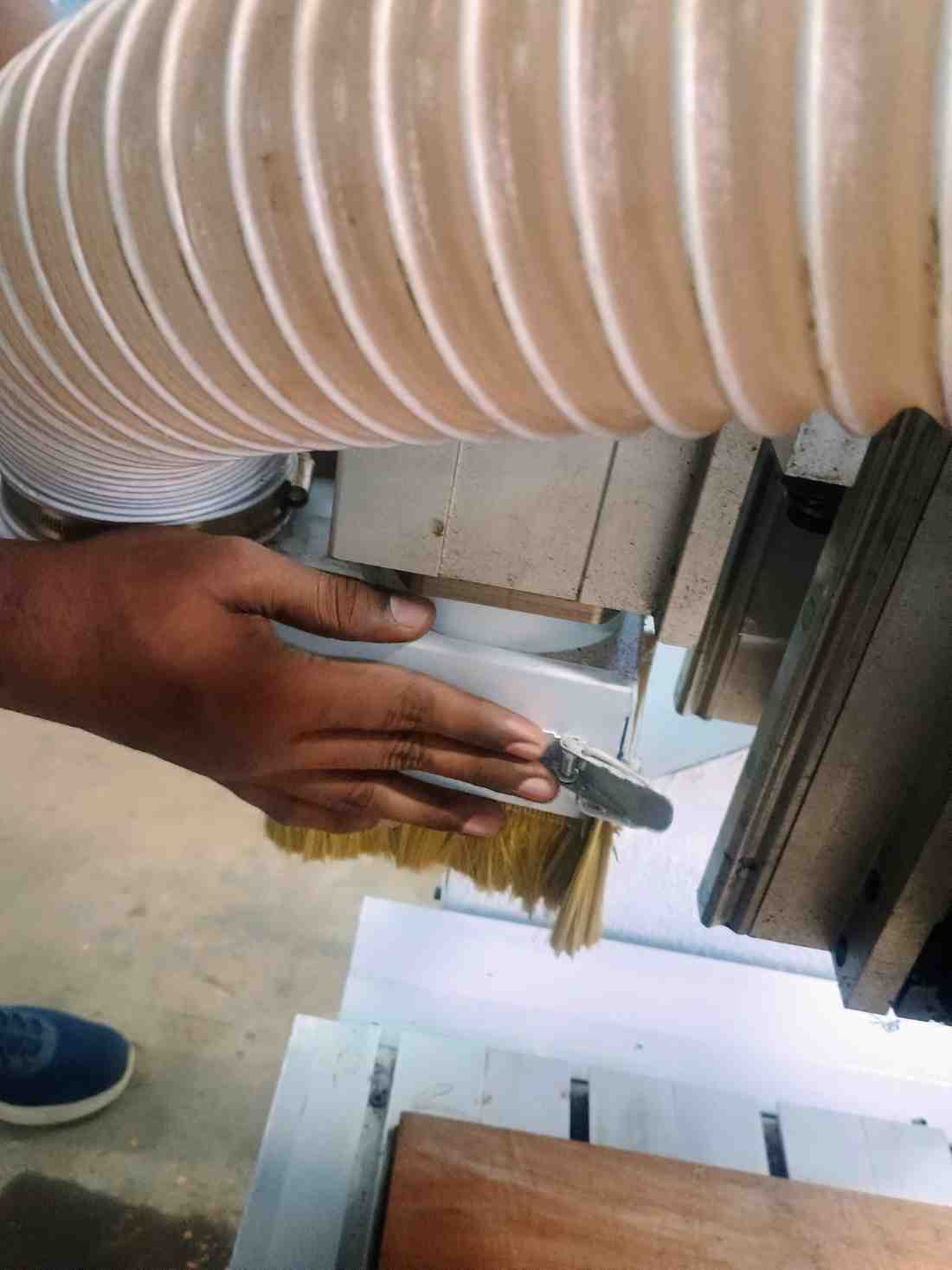
In our CNC router the machine has attached with the dust collector to prevent us from heavy dust while the machine is working.
For setting up the tool in spindle we remove it first from the machine
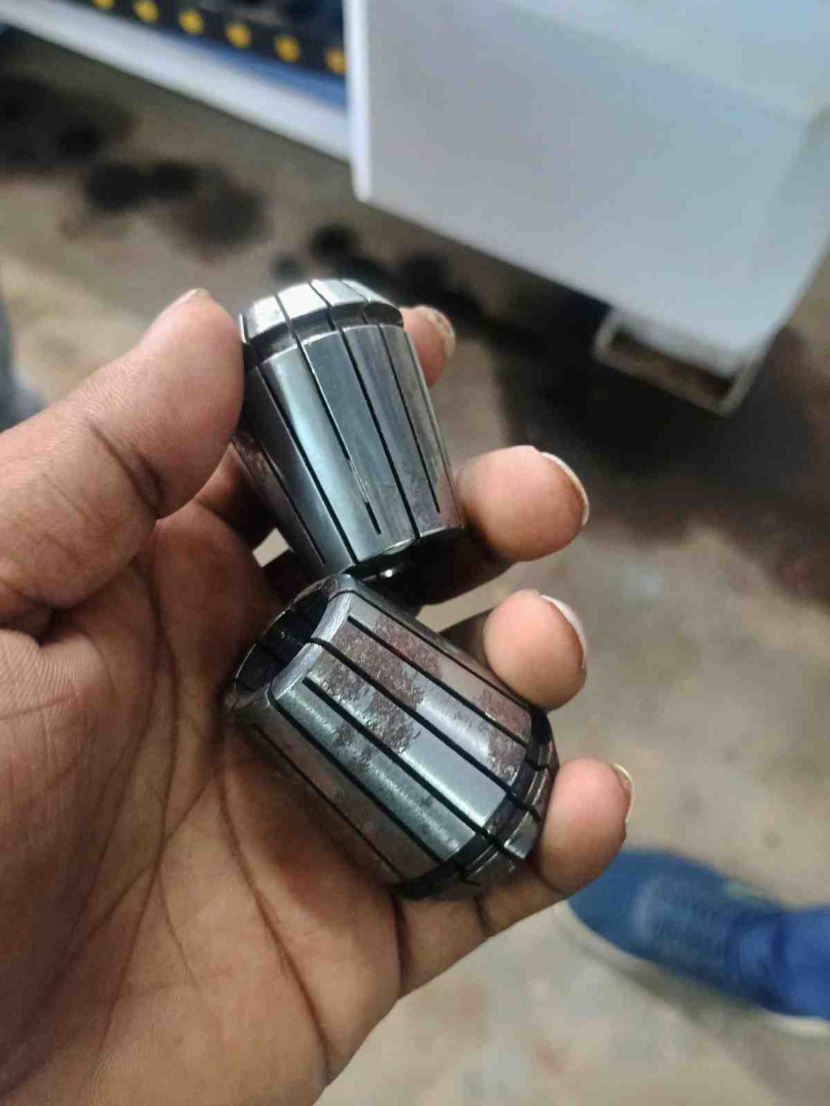
In inner we can see the tool holder like this
In the spindle some brush are also placed for cleaning the dust while the machine is running. We can controlled the spindle movement by using this controller pad
I used the End mill 6mm tool bit for my milling operation according to my design.
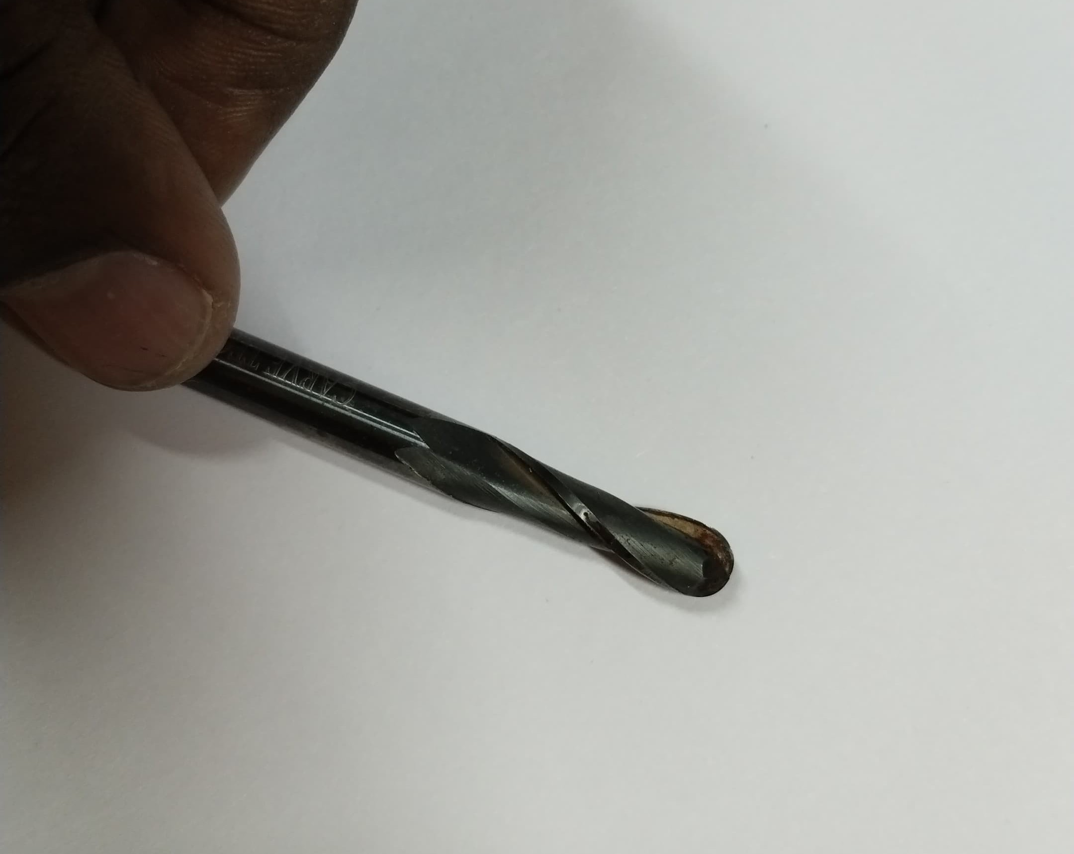
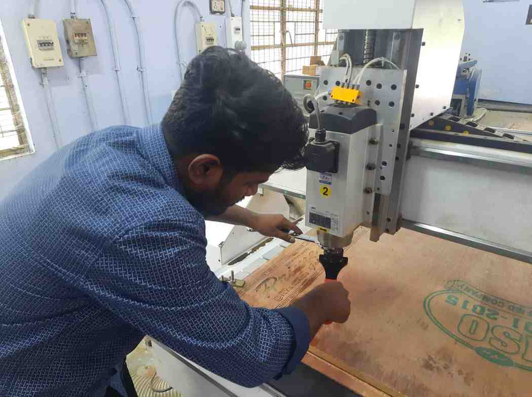
I tightening the tool holder as much as possible without getting slip.
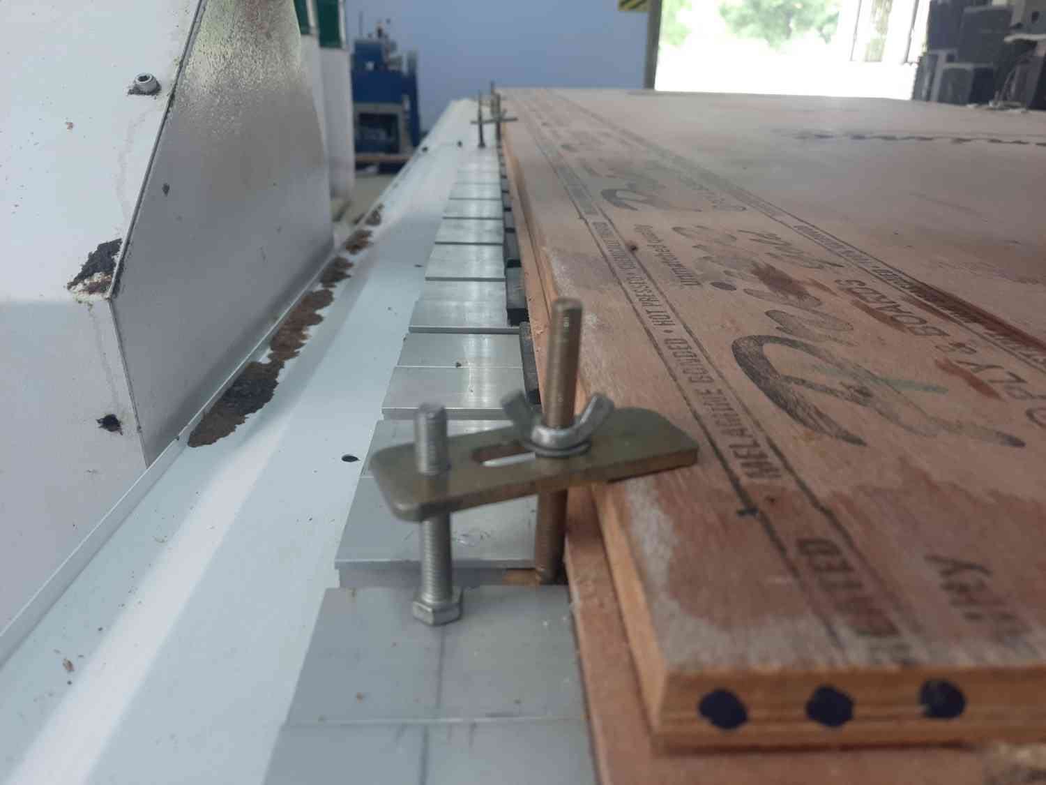
For accurate machining, it is important that the plywood remains flat against the machine bed during cutting. Before clamping, the machine bed was cleaned to remove dust and debris that could create uneven support beneath the sheet.
The plywood was placed directly on the sacrificial board and manually checked.
Multiple clamps were positioned around the perimeter to distribute the holding force evenly across the sheet.
While tightening the clamps, care was taken to apply uniform pressure so that the plywood remained in contact with the spoilboard surface.
Before starting the machining process, several locations across the sheet were checked manually to confirm that the material was seated flat and did not move under light pressure. This ensured consistent cutting depth and improved dimensional accuracy throughout the machining operation.
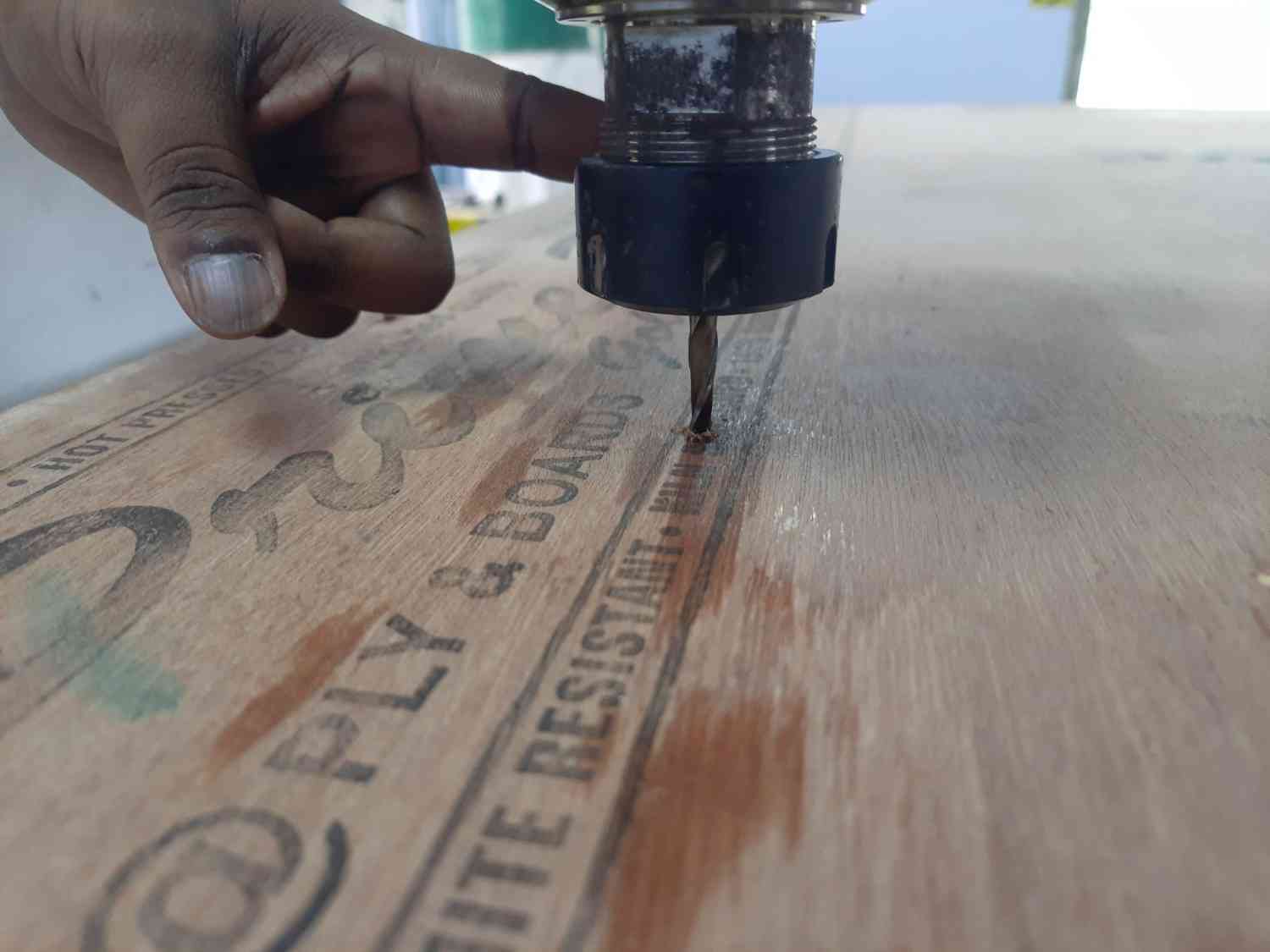
By adjusting the Spindle in Z axis I ensure the tool only touch little bit the surface of the workpiece.
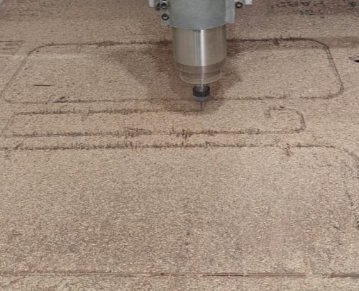
I import the tool path G-code into the machine, start to operate the machine after adjusting the tool into the spindle, make sure the tool is tighted fully otherwise it leads to cause any damage.
Then place the wood on above the machine bed tightly, and start running.
Post-Processing and Assembly
After completing the machining process, all fabricated parts were collected from the machine bed. The machine and surrounding workspace were properly cleaned, and the equipment was safely shut down before proceeding to the assembly stage.
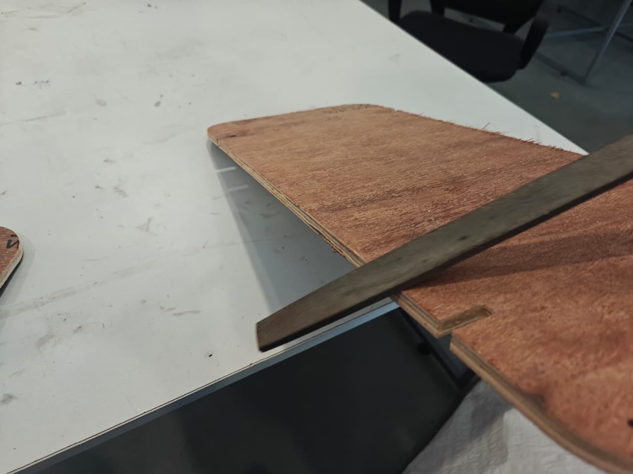
The machined components were then taken to the workbench for post-processing. Although the machining quality was generally good, some edges contained small burrs and unfinished particles generated during the cutting process.
To improve the surface finish and assembly quality, a flat file was used to remove these unwanted edge imperfections. The filing process was performed along the cut edges to create smoother surfaces and eliminate any remaining machining artifacts.
Fit Testing and Adjustment
Once the cleaning process was completed, the fit between the mating parts was evaluated. During the initial test assembly, the joints were found to be slightly tighter than expected. To achieve a better fit, a small amount of material was carefully removed from the joint areas using the file.
After making these minor adjustments, the components were assembled again. The parts aligned properly and could be joined together without excessive force while still maintaining a strong interference fit.
The shelf components were assembled by fitting the interlocking joints together. A mallet was used to gently tap the parts into position, ensuring that all joints were fully seated and securely connected.
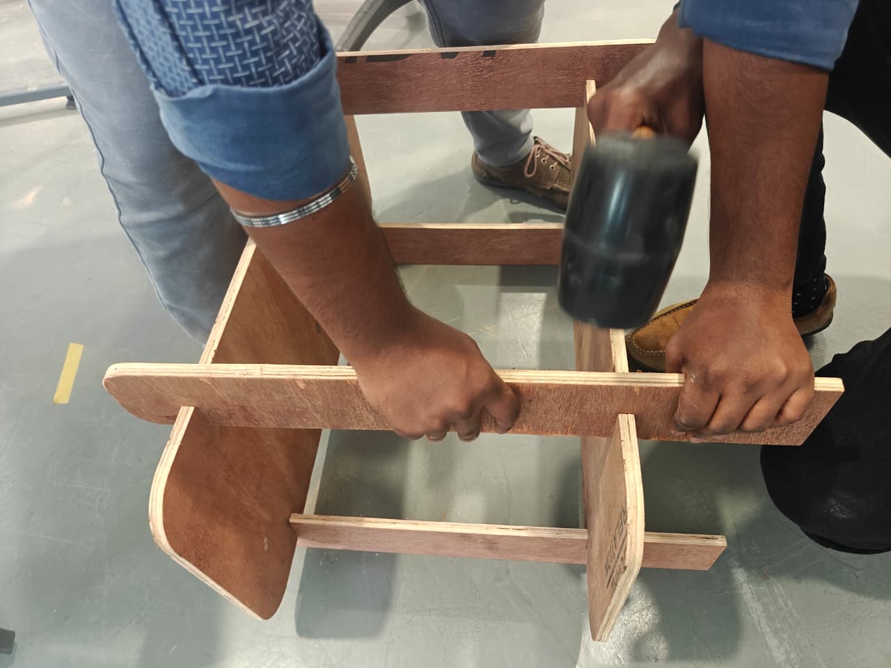
Once assembled, the structure became rigid and stable, matching the intended design objectives. The interlocking joint system provided sufficient strength without requiring additional fasteners or adhesives.
Load Testing
To evaluate the structural performance of the shelf, several books were placed on both the upper and lower shelves. The assembled structure remained stable and showed no visible signs of deformation or instability during the test.
The successful load test demonstrated that the shelf was capable of supporting a significant amount of weight and could be used effectively for storing books and similar items.