Computer Controlled Machining
Home ← →
Objective of this Week
- Complete our lab's safety training
- Test runout, alignment, fixturing, speeds, feeds, materials and toolpaths for your machine
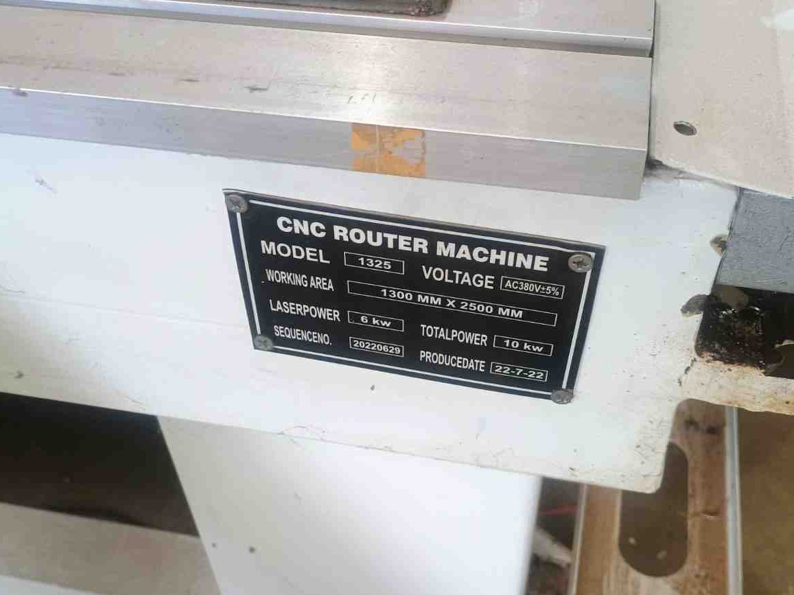
Our Fablab has CNC Wood Router STM 1325 Milling machine
CNC Wood Router
A CNC router is a computer-controlled machining system capable of cutting, engraving, drilling, and shaping a variety of materials such as wood, plywood, MDF, acrylic, PVC foam board, HDPE, and, with suitable tooling and machine rigidity, certain metals such as aluminum. CNC routers provide high precision, repeatability, and efficient material processing for both prototyping and production applications.
Why we want
Traditional woodworking machines require manual operation, which demands a lot of skill, time, and effort. In contrast, a CNC milling machine offers precision, repeatability, and speed.
| Pros | Cons |
| High precision and repeatability | High initial cost |
| Increased productivity and speed | Requires skilled programming and operation |
| Can create complex and intricate designs | Regular maintenance needed for tools and machine |
| Efficient use of material with less waste | Produces wood dust and noise – needs dust collection |
| Compatible with CAD/CAM automation systems | Mostly limited to flat or shallow 3D workpieces |
Safety Precaustions
- Always wear safety glasses and ear protection whenever we operate the milling machine, the wooden parts sometimes will be affected our eyes and also close your ears the machine will make more noise while it running.
- Don’t touch the machine while its fuctioning hands and keep loose clothing away from moving parts otherwise it may lead to severe accident happen.
- Ensure the workpiece is tightly clamped into the machine bed wihtout getting slip. In our machine we tightened by using the C clamp.
- Never allow any person while the machine running, keep eyes on nearby peoples also
- Only change the tools and cleaning operations after we turn off the power of the machine.
- Be alert to emergency stop procedures, if anything worst happens we must ready to do that immediately.
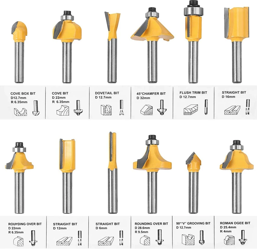
Tools
End Mill (Straight/Cutters)
It is used for cutting straight edges, pockets and contours to removes the materials cleanly with flat bottoms.
Ball Nose Bit
Ideal for 3D contouring and carving with smooth rounded finishes due to its hemispherical tip.
V-Bit (Engraving Bit)
Used for detailed engraving, lettering, and chamfering with V-shaped profiles.
Upcut Bit
Pulls chips upward; best for deep cuts with good chip removal, but may splinter wood surface.
Downcut Bit
Pushes chips downwards; gives clean top surface cuts, ideal for laminates and veneers.
Compression Bit
Combines upcut and downcut flutes; delivers clean top and bottom edges, great for plywood.
Fly Cutter (Surfacing Bit)
Used to flatten and surface large wooden boards or spoilboards quickly and evenly.
Tapered Ball Nose Bit
Used for fine detail 3D carving with added rigidity due to its tapered shape.
Dovetail Bit
Cuts angled slots for joinery work like dovetail joints in furniture making.
Drill Bit
Creates vertical holes; used for doweling or hardware installation in wood.
Machine Operation Training

Before starting the machine
- Machine – cutter should be in good condition, make sure no obstacles around the machine, bed also should be clean.
- Material – make sure it’s compatible and properly fixed into the mahine bed without getting slip.
- Movement – Check the machine movement in all axis(x,y and z) whether it is going properly or not.
- File – check speed/feed settings, cutting depth, machine limits by only give some gap in z axis without touching the tool in workpiece.Furhter try the pause before running the machine whether it is properly respond or not
- Human – be physically & mentally ready, wear proper clothes & protection (ears, face, hands).
During the machine operation
- Machine –Carefully watch tool path, spindle, and cutting depth
- Material – clear out debris after cut the workpice, avoid tool breakage.
- Human – stay away from machine little bit, notice any strange noise/smell, wear protection always.
After work
- Machine – clean dust/debris, check axis and dust box.
- Material – Check once the cutted layer and also check the sacrificial layer for next machine operation
- Tool – Check the tool if in case any breakage happens
Machine Run Testing
Material Used
For this machine testing, we used 12 mm plywood as the workpiece material. Plywood is commonly used in CNC woodworking because it is cost-effective, easy to machine, dimensionally stable, and suitable for furniture and structural applications. The layered construction of plywood also provides good strength compared to solid wood.
Fuison 360
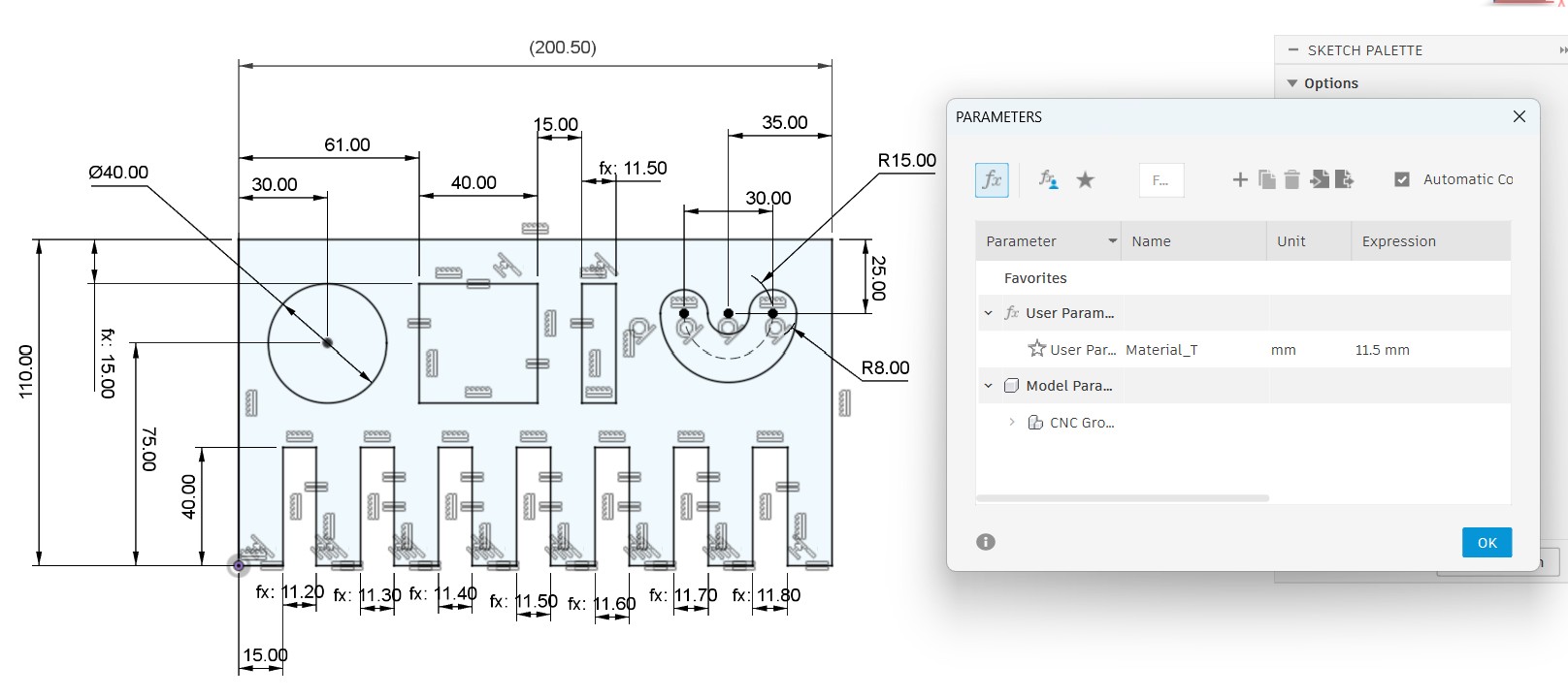
We design the testing file to test our CNC millilng machine by using the Fusion 360 software
After designing it set the dimensions for testing the workpiece outcome.
Artcam
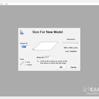
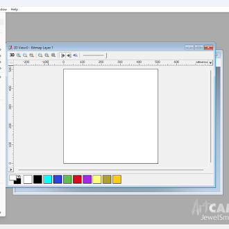
For the tool path generation we used the Artcam software
We upload the file into the software and setting up the required parameters
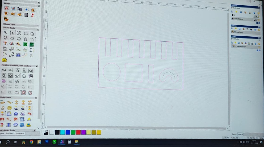
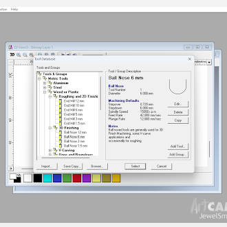
Then we converted it into gcode for the milling operation.
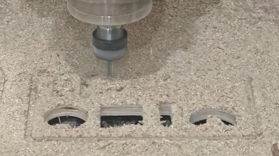
Machining
Workholding and Fixturing
Proper fixturing is important to prevent vibration and movement during machining.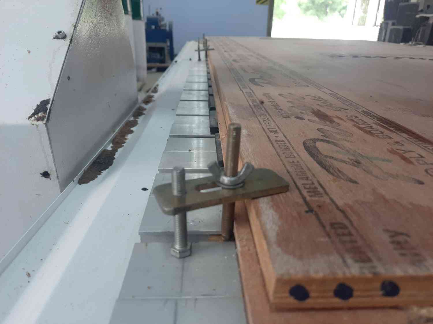
Tool Selection
For this test, we selected a 6 mm flat end mill.Machining Parameters
| Parameter | Value |
| Material | 12 mm Plywood |
| Tool Diameter | 6 mm End Mill |
| Spindle Speed | 12,000 RPM |
| Feed Rate | 1,500 mm/min |
| Depth per Pass | 6 mm |
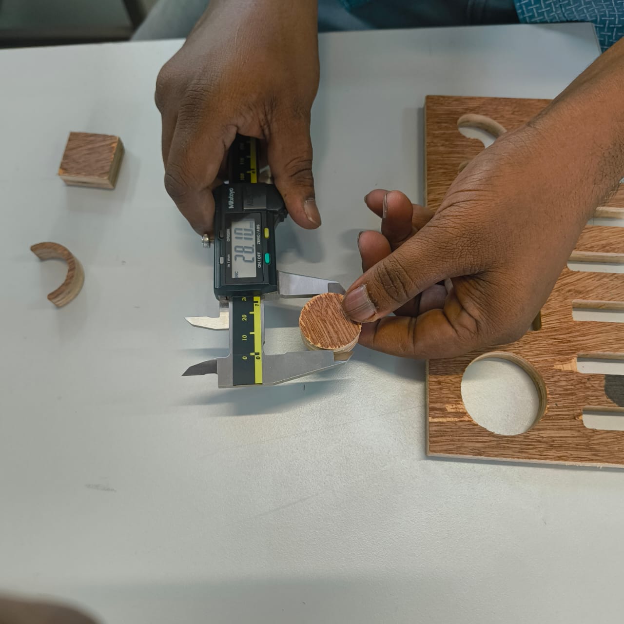
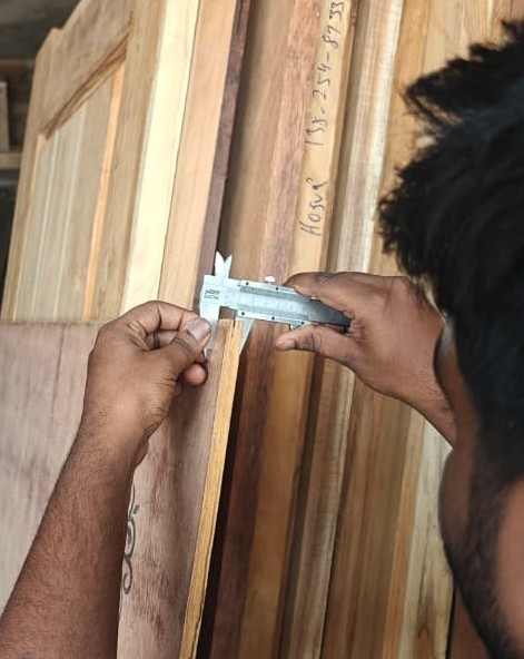
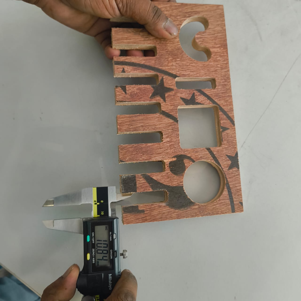
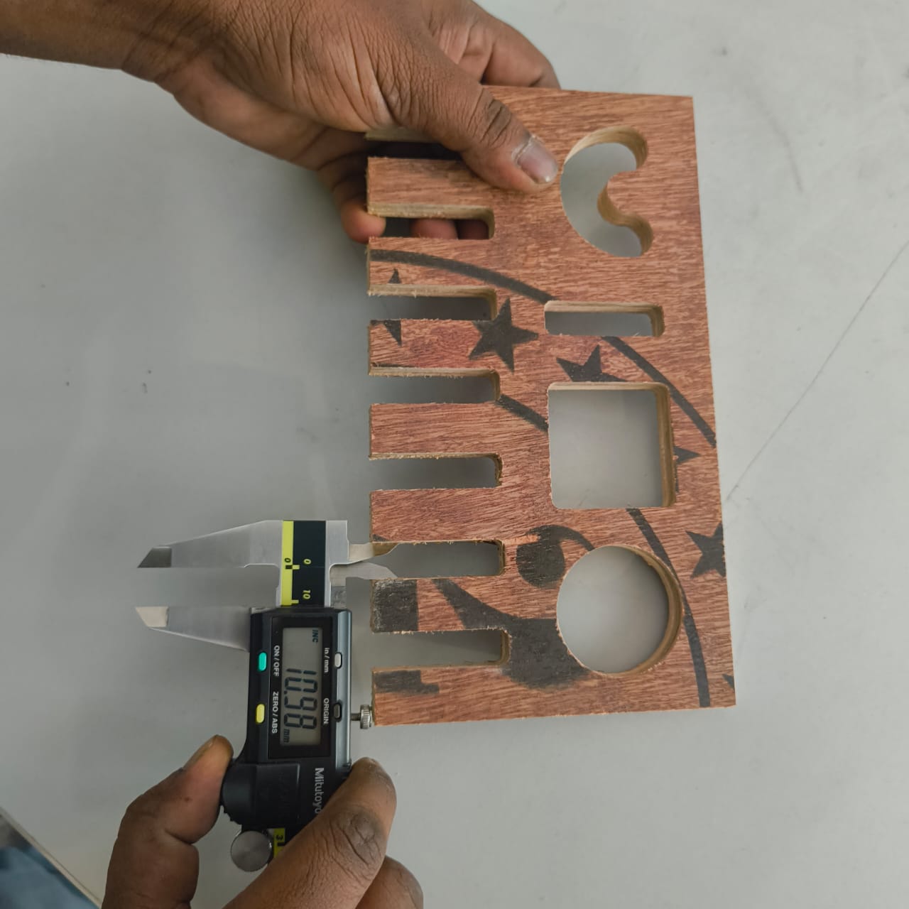
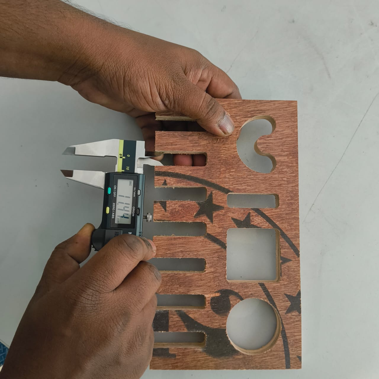
Dimension checking
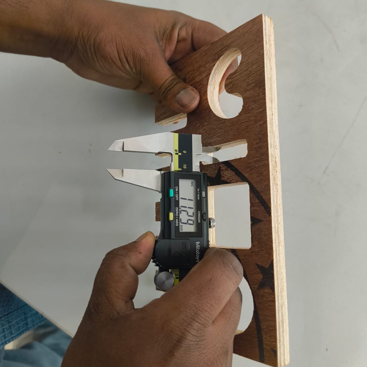
After completing the machining process, we performed a dimensional inspection to evaluate the manufacturing accuracy of the fabricated parts. A Vernier caliper was used to measure the critical dimensions and compare them with the original CAD design values.
The inspection began with the finger joints, as they are important features that directly affect the assembly quality and fit between components. During the design stage, a clearance variation of approximately 0.1 mm was considered to accommodate machining tolerances and material behavior.
The designed finger joint dimensions ranged from 11.2 mm to 11.8 mm. Each finger joint was measured individually using the Vernier caliper, and the results were compared against the intended dimensions to identify any dimensional deviations introduced during machining.
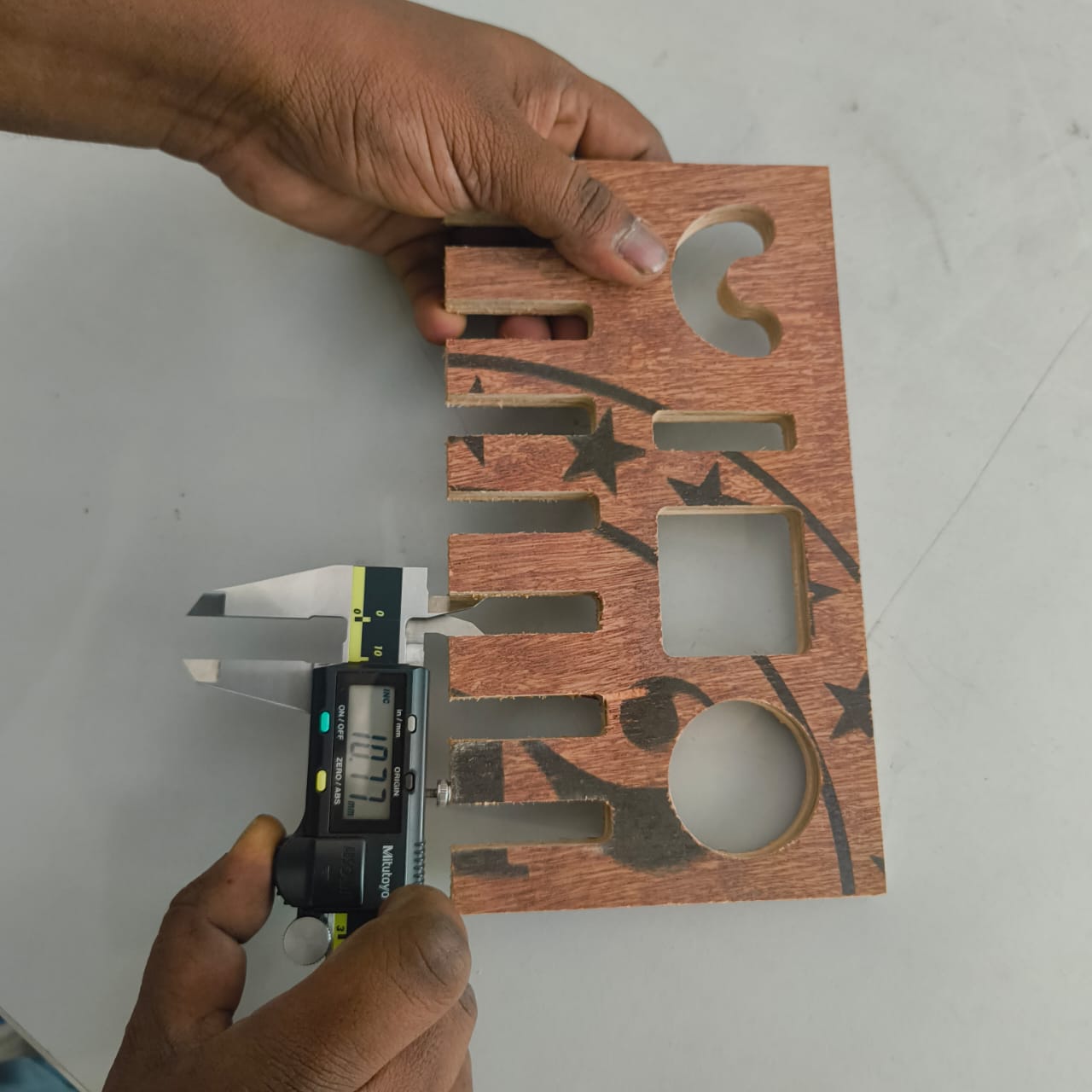
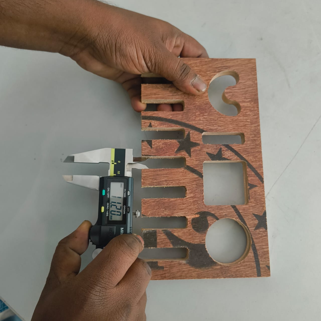
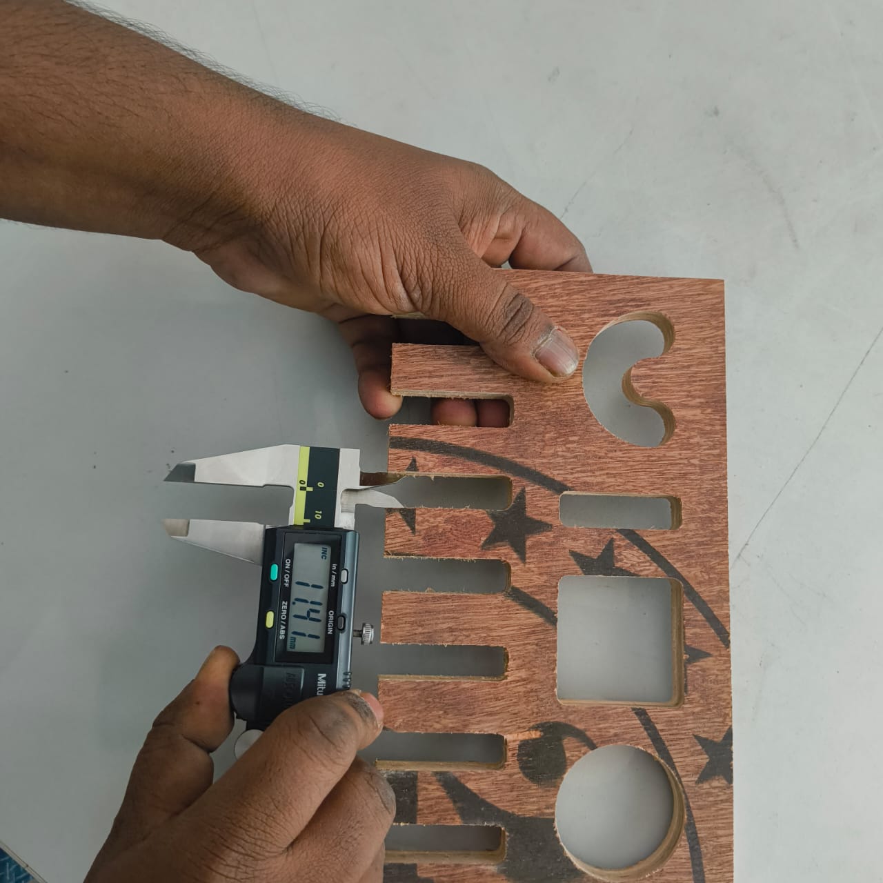
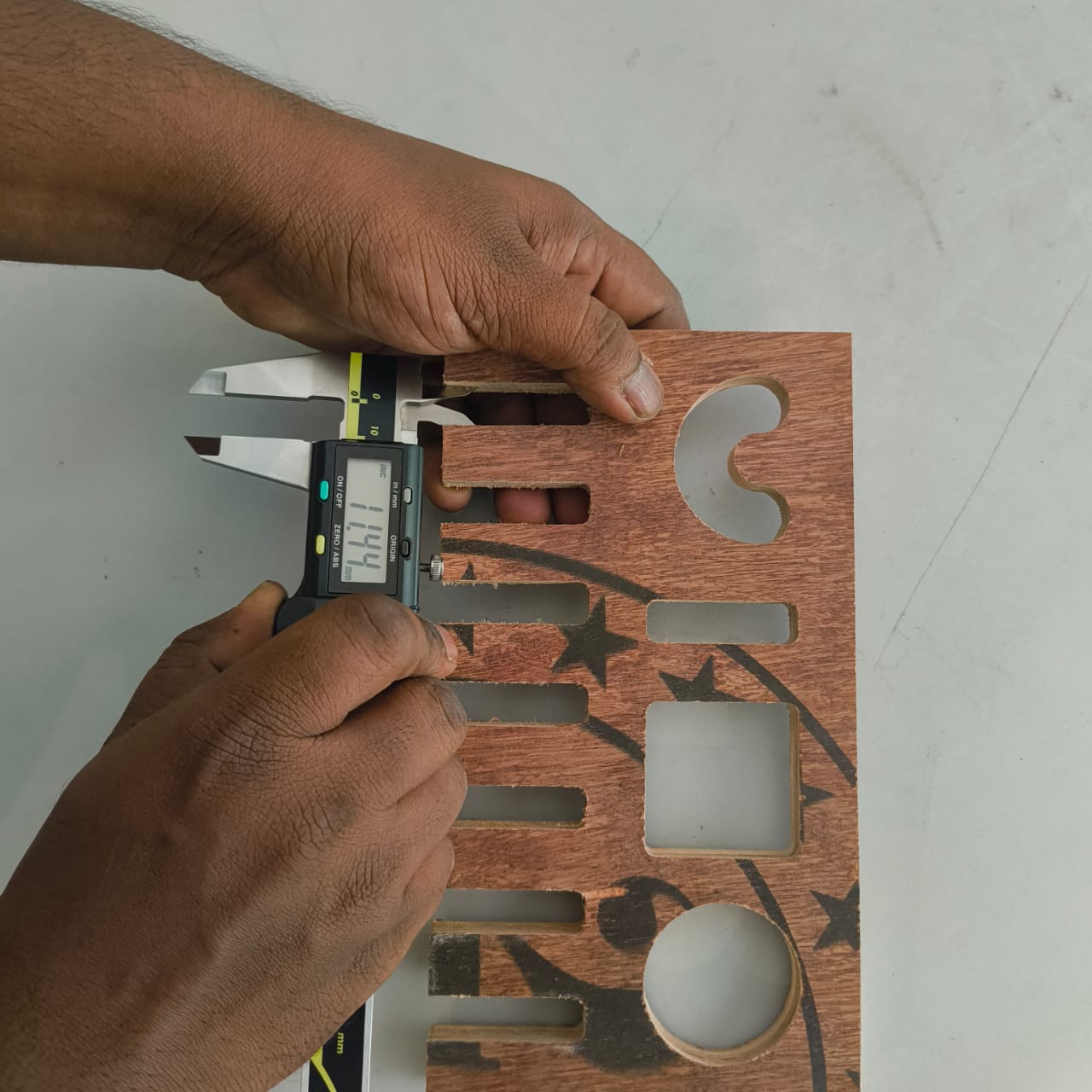
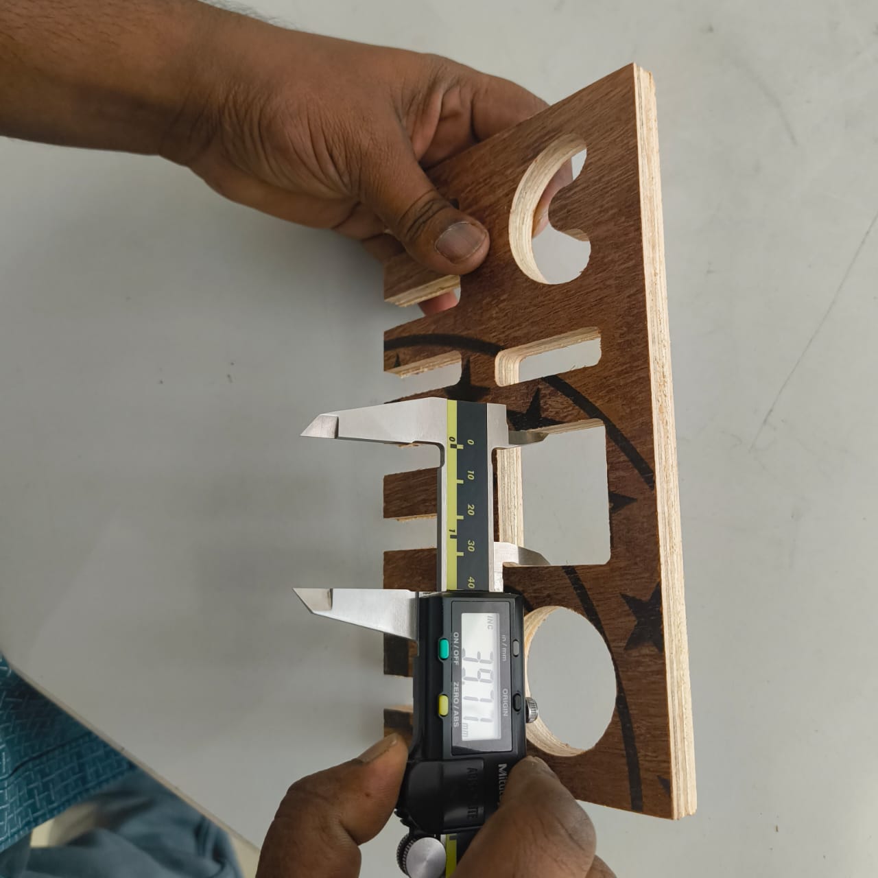
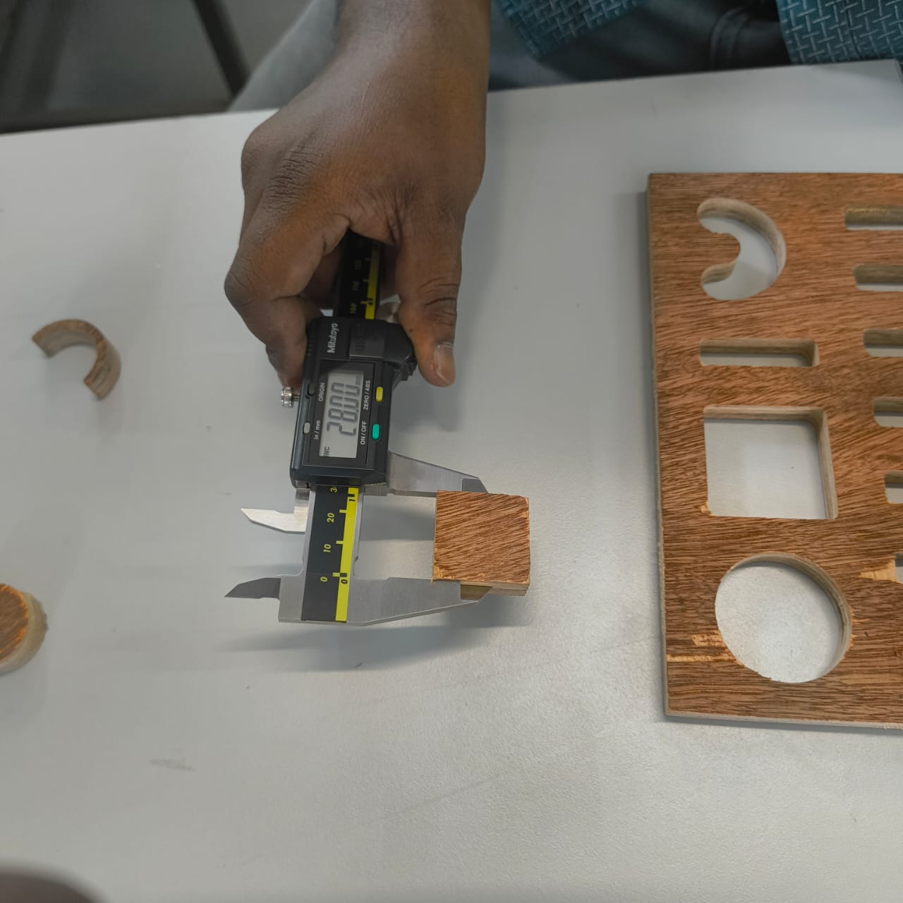
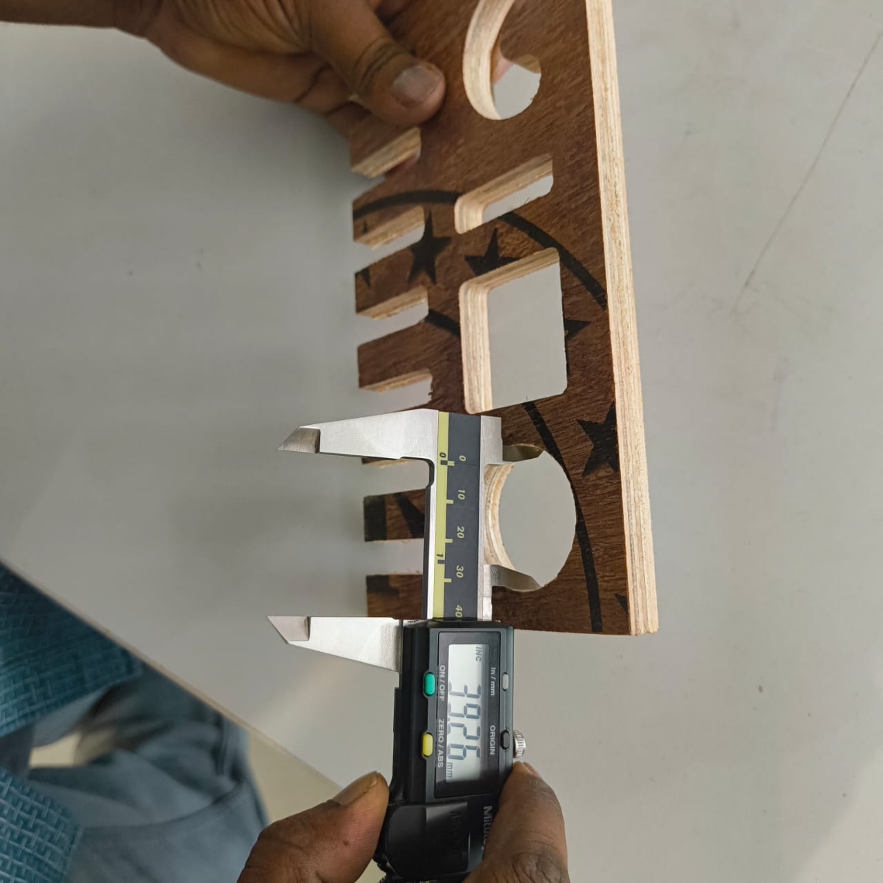
Various shapes and profiles were checked to evaluate edge quality, dimensional consistency, and the accuracy of the toolpath execution.
The inspection helped verify whether the manufactured parts met the design requirements and provided valuable information about machining tolerances, fit quality, and areas that may require adjustment in future iterations.