System Integration
Individual Assignment :
System Integration
System integration means connecting all the parts of my project—like sensors, actuators, microcontrollers, and other hardware or software—so they work together as one system. It’s about making sure everything is linked properly and data flows smoothly between the components. Instead of each part working alone, integration helps the whole setup perform reliably as a single unit. This step is key to making sure the project works well overall.
Idea Sketch
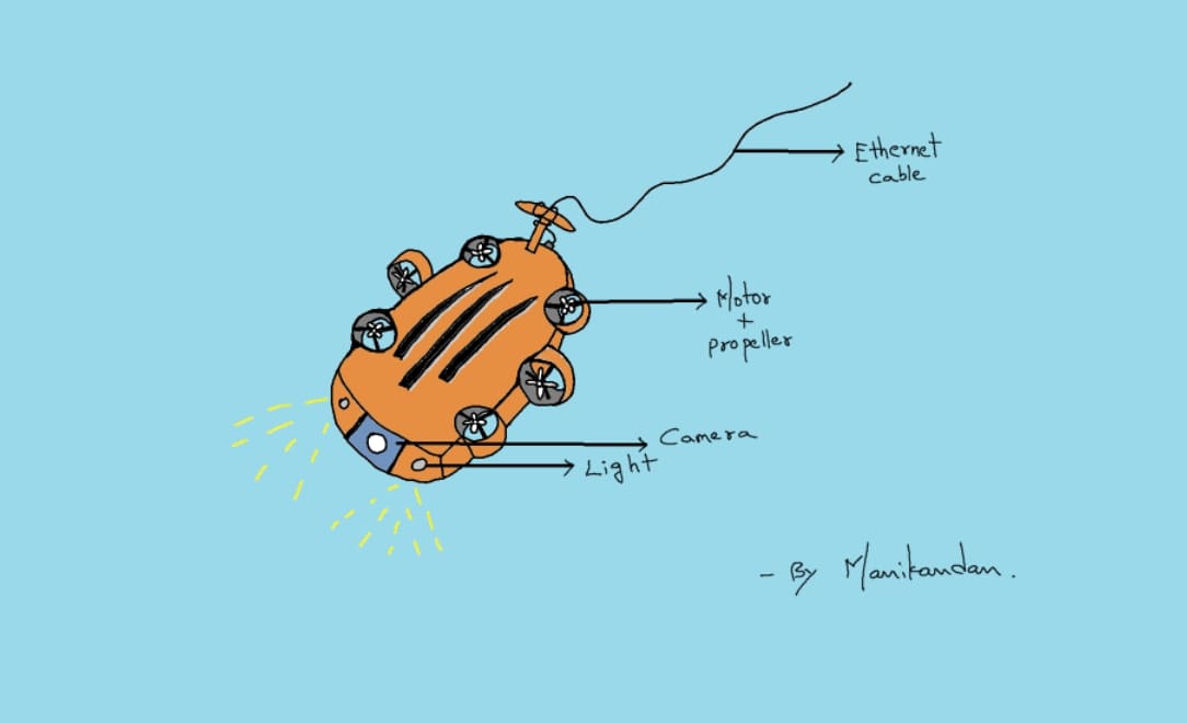
Before starting the detailed design and fabrication process, I created an initial concept sketch to visualize the overall structure and functionality of the underwater drone.
This sketch served as the foundation for the development of the project and helped me define the key mechanical and electronic subsystems required for the prototype.
The concept illustrates the intended arrangement of the drone body, propulsion system, electronic components, and overall form factor.
Throughout the project, several modifications were made based on fabrication constraints, testing results, and design improvements. However, the original sketch remained an important reference during the development process.
The idea sketch can be viewed using the link below:
System Integration Flow Chart
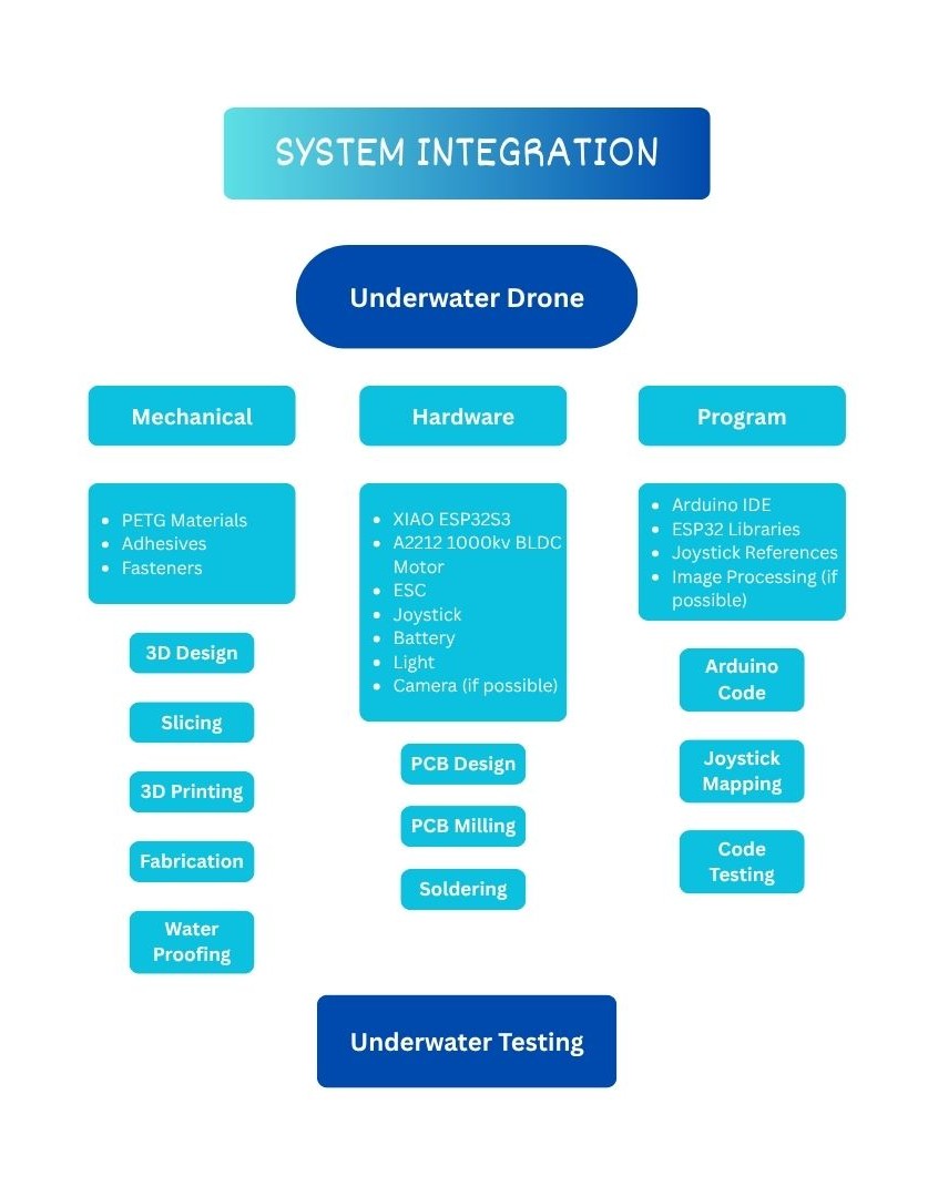
Mechanical
PETG Materials
I used the PLA + materials for my Underwater drone Printing because of it has highly capable of withstand the underwater pressure comparitively PLA.
Adhesives
I used some adhesives to make it stick together by motor hub due to the electronic components are kept inside without getting damage
Fasteners
By using the Fasteners I can tightly joint both top and bottom parts, but still it couldn’t enough to make it waterproofing completely.
Hardware
XIAO ESP32S3 board
I used the XIAO ESP32S3 board for the Motor control and if possible will also check the image processing
BLDC Motor and ESC
For my drone I used the 6 BLDC motor to achieve the 8 DOF in underwater, and to control the BLDC motor we should use the Electronic speed controller as well
Battery
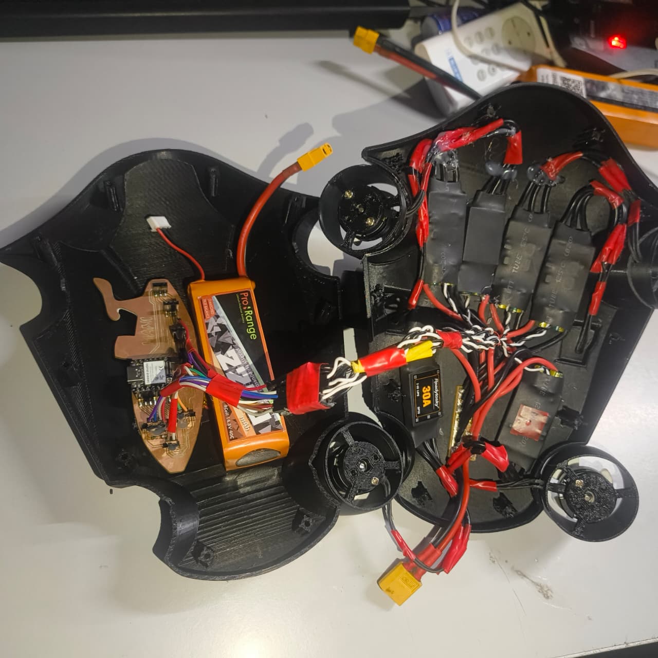
For the power source I use the battery Pro Range 4Cell 14.8V 40C 2200mAh
Program
Arduino IDE
For my microcontroller I will use the Arduino code to operate the BLDC Motor, so I work on Arduino IDE
ESP32 Libraries
I installed the required libraries to work on the XIAO ESP32S3 board
User Flow Diagram
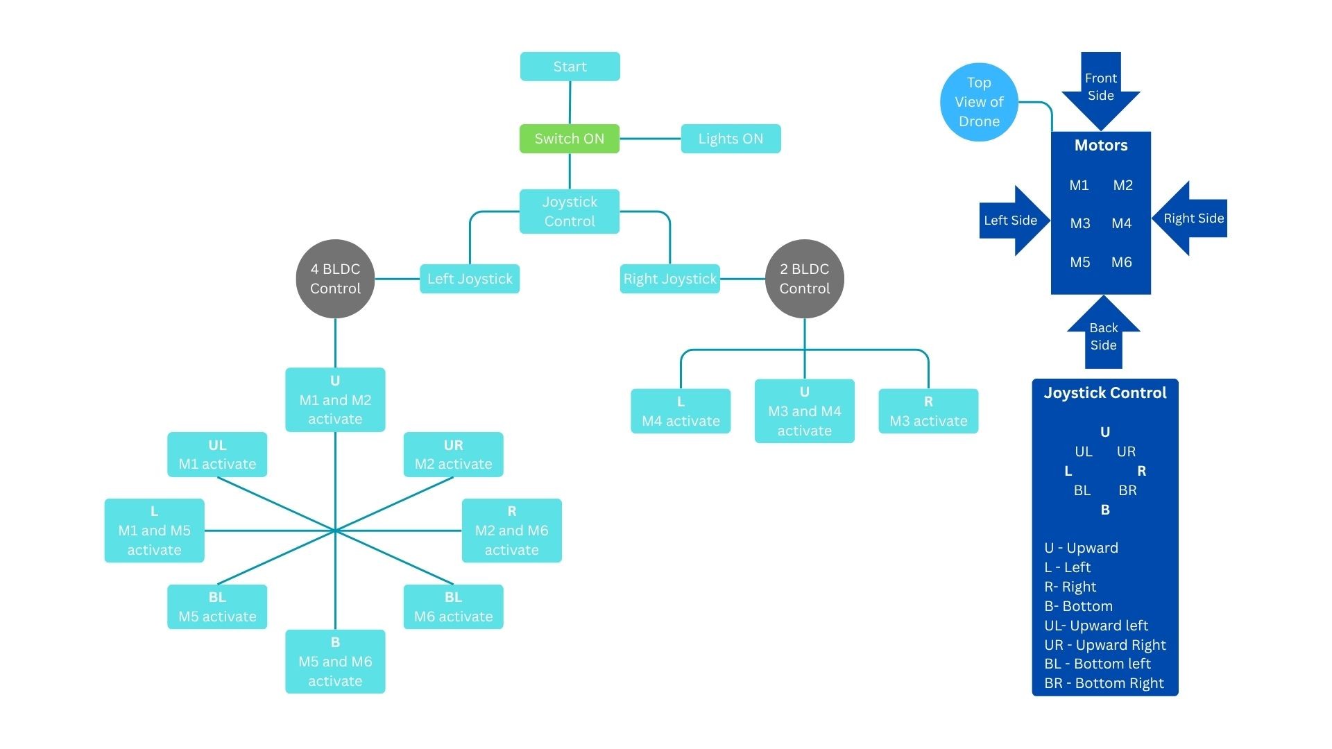
The above flowchart explains how the underwater drone is controlled using a dual-joystick system and six BLDC motors.
When the system is powered ON, the lighting system is activated and the drone becomes ready for operation. The joystick controller is divided into two sections:
Left Joystick – Vertical Movement Control - The left joystick controls four vertical thrusters (M1, M2, M5, and M6), which are responsible for depth control and vertical positioning.
Right Joystick – Horizontal Movement Control - The right joystick controls two horizontal thrusters (M3 and M4), which are responsible for directional movement.
Motor Arrangement
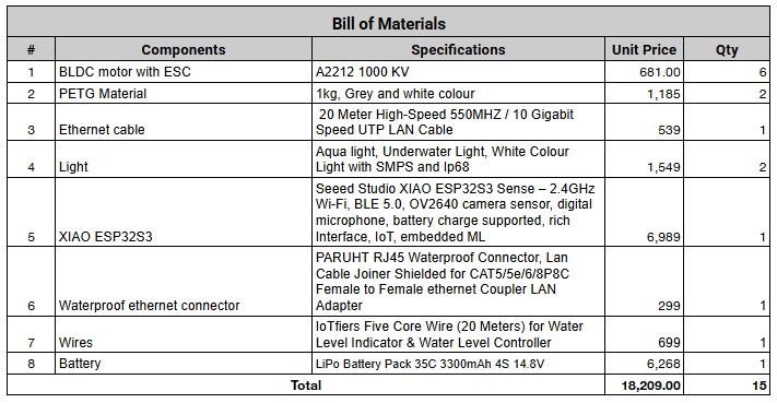
BOM
3D Designing
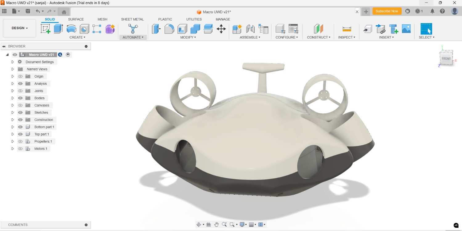
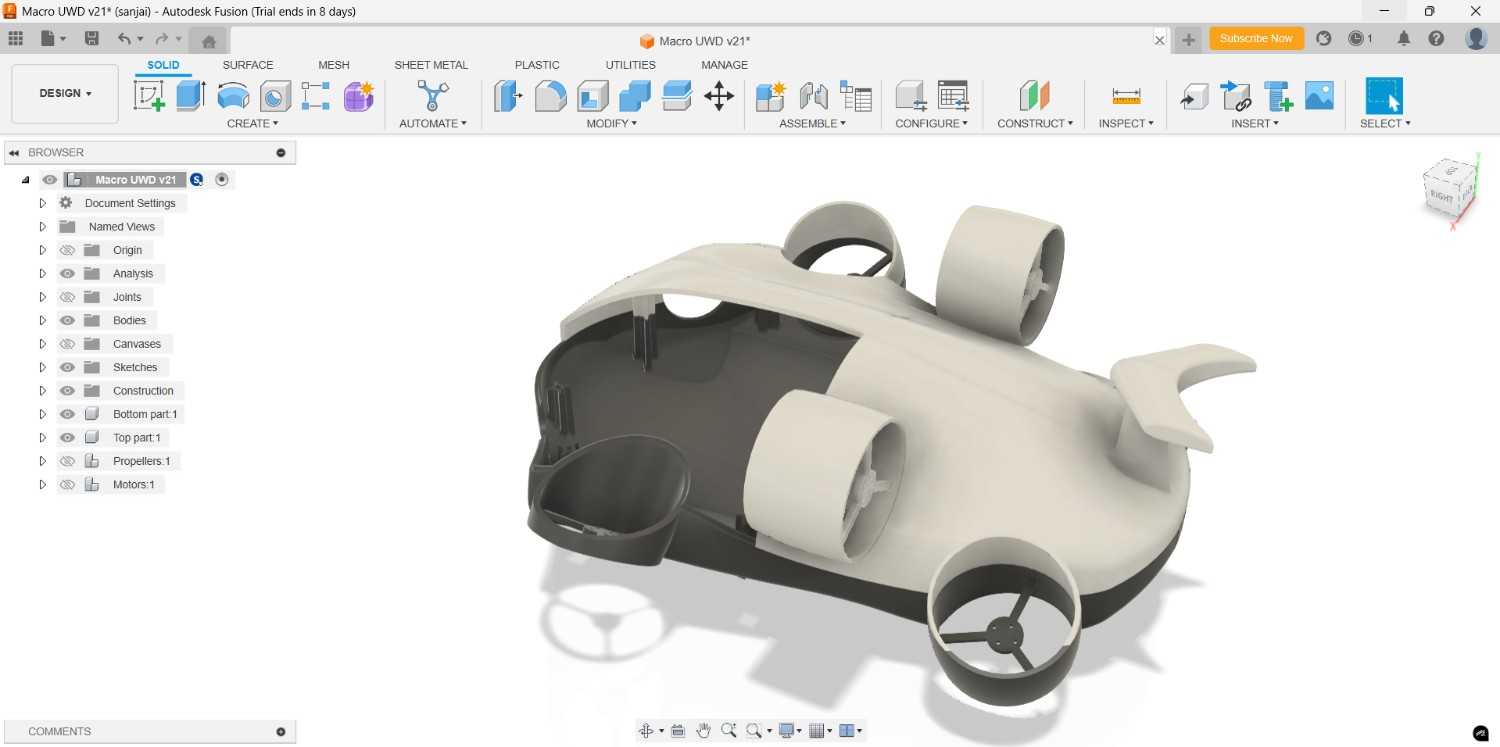
The complete 3D design process, including concept development, CAD modeling, design iterations, structural modifications, motor hub redesign, scaling considerations, and preparation of manufacturing files, is documented separately on my Final Project 3D Design page.
For detailed information regarding the design and development of the underwater drone you can navigate to the following page:
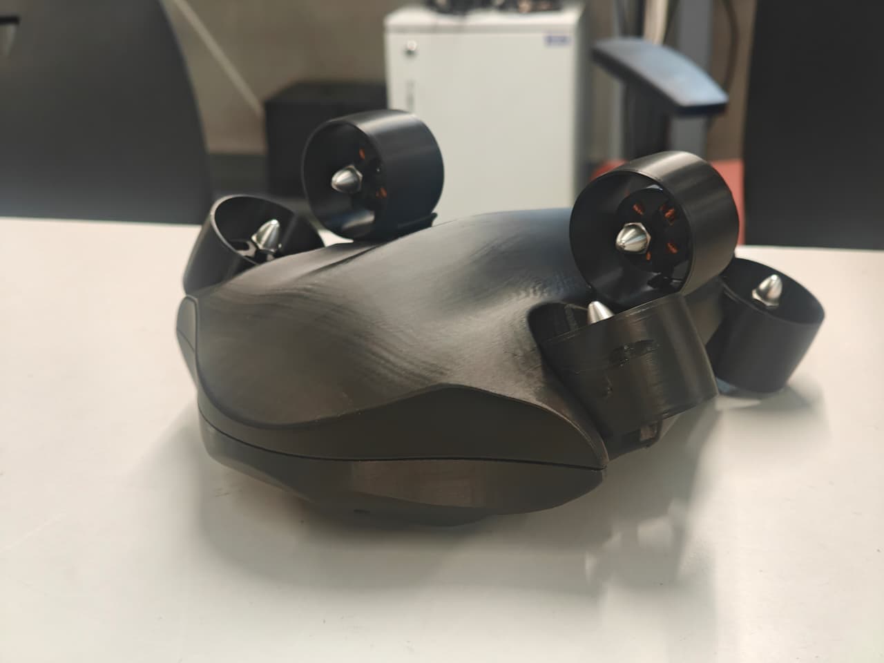
3D Printed Enclosure Assembly
For this project, the underwater drone is presented as a conceptual design. The focus is on demonstrating the overall structure, component arrangement, and operating concept rather than developing a fully waterproof enclosure.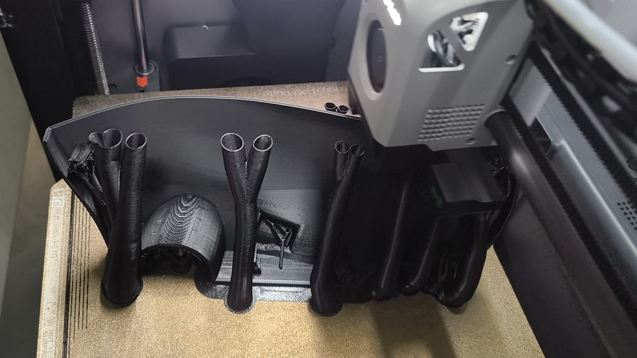
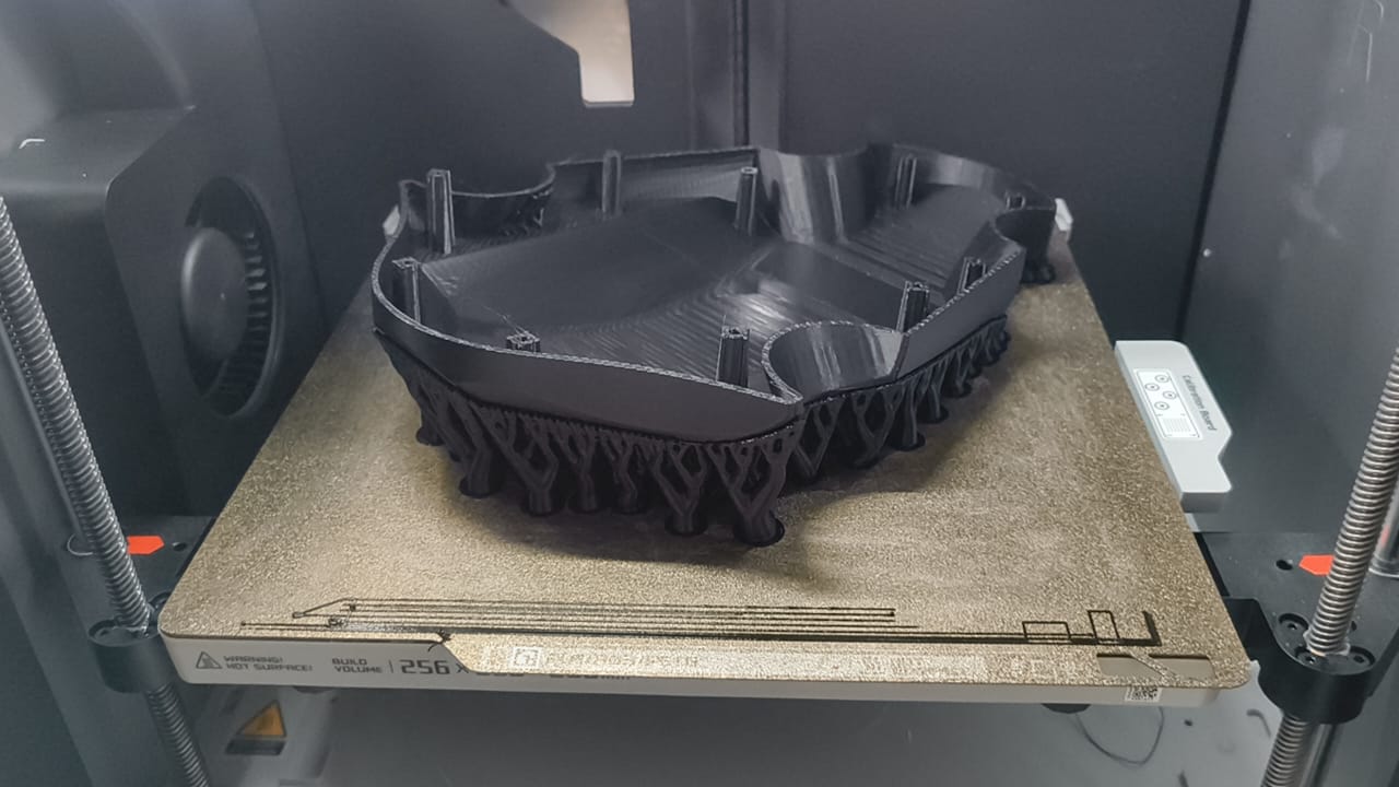
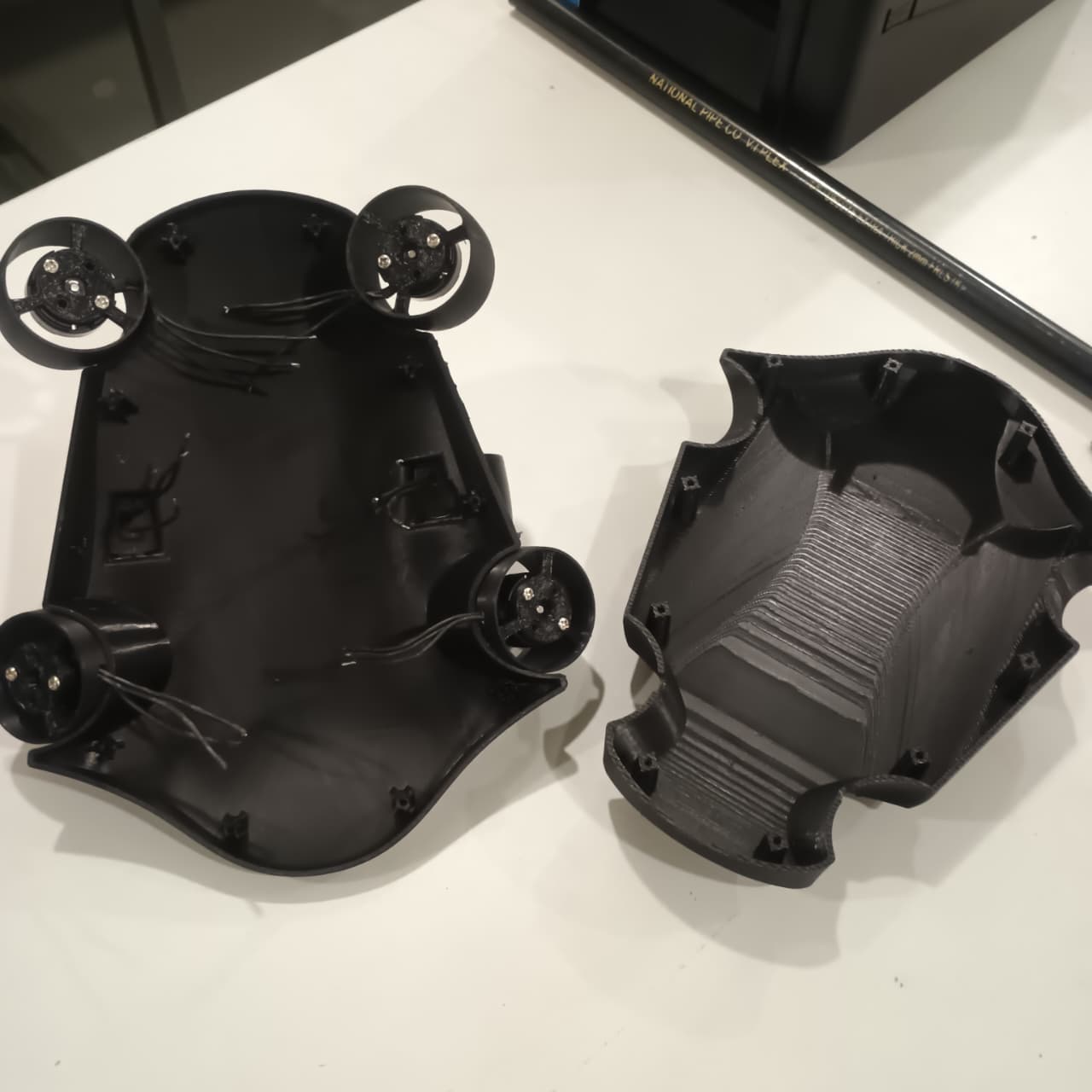
The complete 3D printing workflow, including design preparation, slicing parameters, material selection, print settings, fabrication process, and post-processing details, is documented separately on my Final Project 3D Printing page.
For detailed information regarding the manufacturing of the underwater drone components you can navigate this following page:
Electronics Design
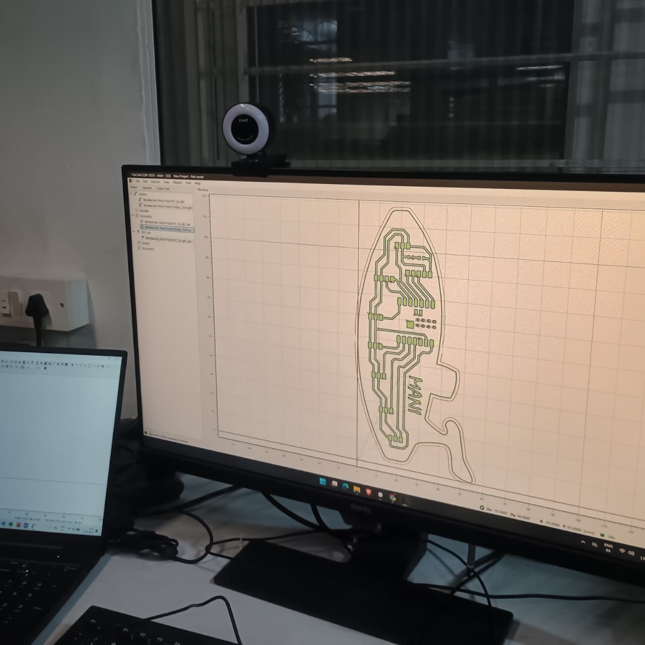
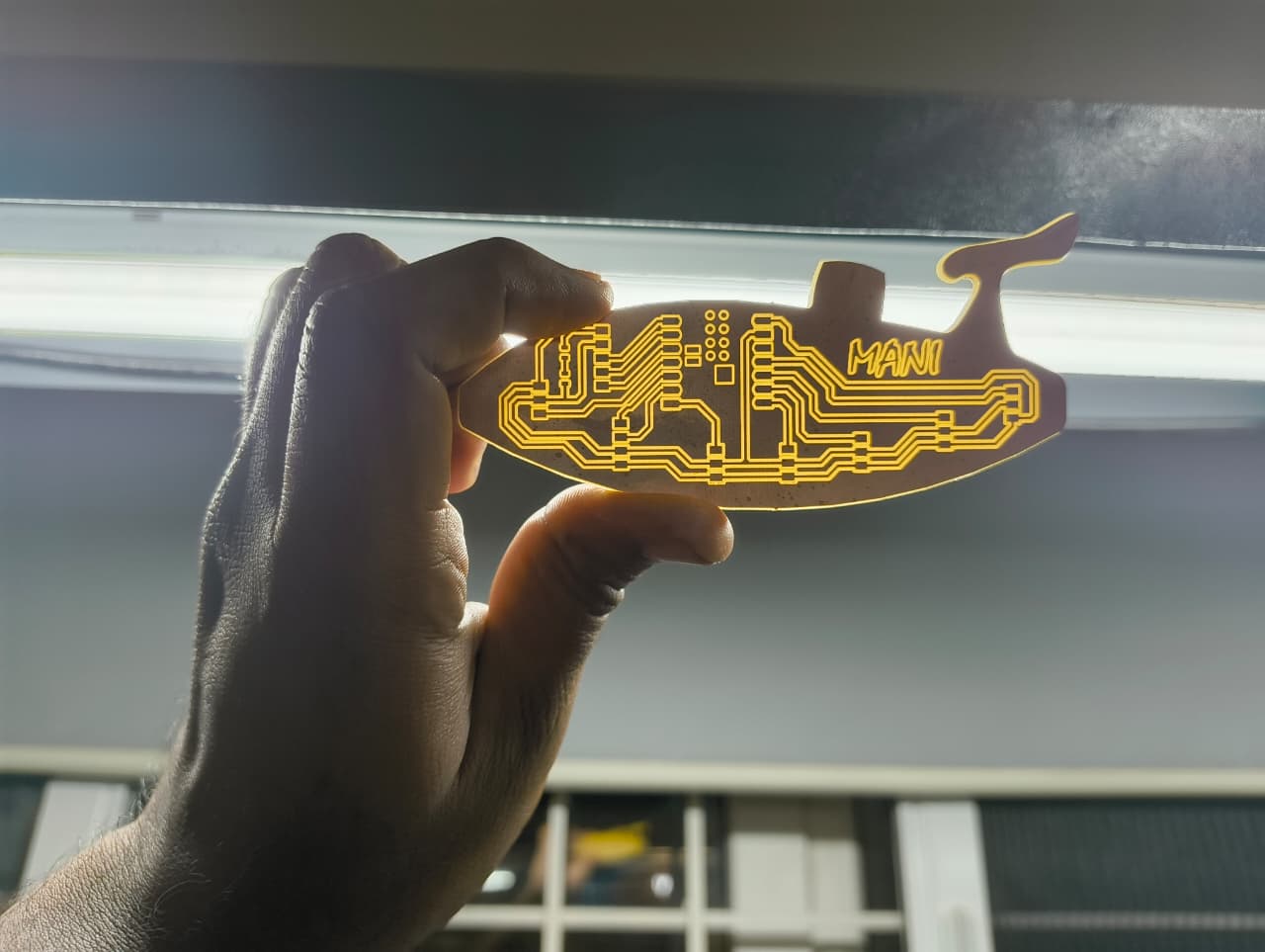
The complete electronic design process, including schematic development, PCB layout design, component selection, trace routing, Gerber file generation, PCB fabrication, soldering, and electronics integration, is documented separately on my Final Project Electronics Design page.
For detailed information regarding the electronic system development of the underwater drone you can check the following page:
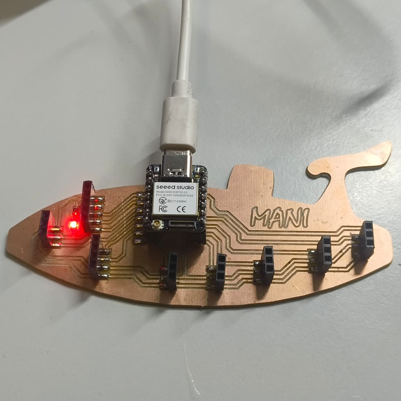
Electronic Integration
The XIAO ESP32S3 acts as the central controller of the underwater drone. Instead of using a physical joystick, the drone is controlled through a web-based interface hosted by the microcontroller.
When the system is powered on, the ESP32S3 creates its own Wi-Fi hotspot. A mobile phone can connect directly to this hotspot, and by entering the assigned IP address into a web browser, a control page is displayed. This page contains a virtual joystick interface that allows the user to control the movement of the underwater drone wirelessly.
The ESP32S3 receives commands from the web interface and controls the six BLDC motors through the ESCs using simple HIGH and LOW signals.
When a control button is pressed, the corresponding motor is activated, and when the button is released, the motor stops. Speed adjustment was not implemented in this proof-of-concept (PoC) stage.
The battery supplies power to the ESCs and electronic components. The complete system was tested to verify reliable wireless communication and motor response.
Wireless Control System
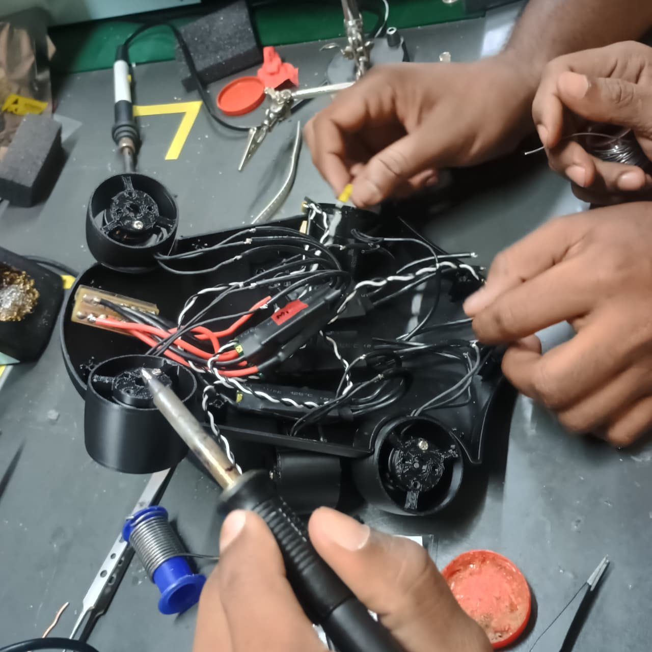
Wiring and Cable Management
Since the project is intended for underwater operation, cable management is an important consideration.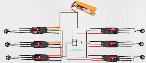
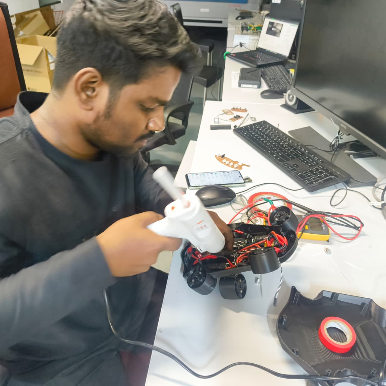
The complete fabrication process, including 3D printing, PCB board, component assembly, mechanical integration, post-processing, and final prototype construction, is documented separately on my Final Project Fabrication page. For detailed information regarding the fabrication and assembly of the underwater drone, please refer to the following page: Final Project Assembly
The final assembly includes:
Connection to Earlier Assignments
This project integrates the outcomes from multiple previous assignments:
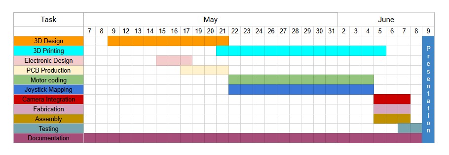
Project Schedule
Conclusion
For this week System Integration I concentrated on clear understanding of how various components interact in this project.
Know about how to follow them properly to fininsh it asap within the short period of time
I set the clear road map to my final project, so I will achieve the target milestones one by one by focusing and speed up myself.