Output devices
Learning outcomes
Demonstrate workflows used in controlling an output device(s) with MCU board you have designed.
Group assignment
The group assignment for this week here is the summary of what we have done:
- Measure power consumption of output devices.
- Document findings on group page.
- Reflect on individual page.
DC Power Supply: Instek GPD-3303D
- Converts AC to DC.
- Provides stable output voltage.
- Maximum voltage: 30V
- Maximum current: 3A per channel, 5A total
- Accuracy: ±(0.1% + 2 digits)
Output Device 1: DC Motor
- Converts electrical to mechanical energy.
- Voltage range: 6-12V.
- Powered at 12V, drew 0.04A.
- Power consumption: 0.48W
- Stalled at 12V, drew 1.29A.
Output Device 2: White LED
- Emits white light with forward current.
- Voltage range: 3-3.4V.
- Powered at 3.2V, drew 0.02A.
- Power consumption: 0.064W
Individual assignment
This week's focus is on output devices. While I previously designed a board for controlling leds by push bottons and I have already some pins to add servo motor with considering the common ground for Week 8, I'll be reusing the same board this time to control a servo motor instead.
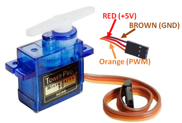
I will be utilizing an SG90 servo motor for this project. The SG90 servo motor features three lines: two for power supply and the third for data transmission, allowing control over the motor's position of rotation through PWM (Pulse Width Modulation) signals.
A servo motor, like the SG90, is a type of motor commonly used in robotics and other applications where precise control of angular position is required. Unlike typical DC motors, servo motors can rotate to specific angles based on the duration of an input pulse.
Pulse Width Modulation (PWM) is the technique used to control the position of a servo motor. PWM works by varying the width of pulses in a periodic signal, where the width of the pulse corresponds to a specific position of the servo motor's shaft.
In the case of the SG90 servo motor, the data line is connected to a microcontroller's PWM-capable GPIO pin. By sending PWM signals with varying pulse widths to the servo motor, we can control its position. Typically, a pulse width of around 1ms corresponds to one extreme position (e.g., 0 degrees), while a pulse width of around 2ms corresponds to the opposite extreme position (e.g., 180 degrees). Intermediate positions can be achieved by adjusting the pulse width accordingly.
In summary, the relationship between the servo motor and PWM lies in the fact that PWM signals are used to control the position of the servo motor's shaft, allowing for precise angular positioning in various applications.
Below is a sample code written in Arduino IDE for controlling a servo motor connected to pin 26 and an LED connected to pin 1. The servo motor will move to a specific angle when a push button connected to pin 29 is pressed:
#include <Servo.h>

                                        #define SERVO_PIN 26  // Define the pin for the servo motor
                                        #define LED_PIN 1     // Define the pin for the LED
                                        #define BUTTON_PIN 29 // Define the pin for the push button

                                        Servo servo; // Create a servo object

                                        void setup() {
                                          servo.attach(SERVO_PIN); // Attach the servo to its pin
                                          pinMode(LED_PIN, OUTPUT); // Set the LED pin as an output
                                          pinMode(BUTTON_PIN, INPUT_PULLUP); // Set the button pin as an input with internal pull-up resistor
                                        }

                                        void loop() {
                                          if (digitalRead(BUTTON_PIN) == LOW) { // Check if the button is pressed
                                            // Turn on the LED
                                            digitalWrite(LED_PIN, HIGH);

                                            // Move the servo to a specific angle (e.g., 90 degrees)
                                            servo.write(90);

                                            // Add a delay to ensure stable servo movement
                                            delay(500);
                                          } else {
                                            // Turn off the LED
                                            digitalWrite(LED_PIN, LOW);

                                            // Move the servo to another angle (e.g., 0 degrees)
                                            servo.write(0);

                                            // Add a delay to ensure stable servo movement
                                            delay(500);
                                          }
                                        }
To use the code you've provided on the Seeed Xiao RP2040, here’s an explanation and steps to download it:
Code Explanation
This Arduino sketch controls a servo motor and an LED based on the state of a push button:
Libraries Used: The code includes the
Servo.hlibrary for servo motor control.Pin Definitions:
SERVO_PIN: Defines the pin connected to the servo motor.LED_PIN: Defines the pin connected to an LED.BUTTON_PIN: Defines the pin connected to a push button with internal pull-up resistor enabled.
Setup Function (
setup()):servo.attach(SERVO_PIN): Attaches the servo motor to the defined pin.pinMode(LED_PIN, OUTPUT): Sets the LED pin as an output.pinMode(BUTTON_PIN, INPUT_PULLUP): Sets the button pin as an input with internal pull-up resistor enabled.
Loop Function (
loop()):- Checks if the button (
BUTTON_PIN) is pressed (LOWstate). - If pressed, it turns on the LED (
LED_PIN) and moves the servo to 90 degrees (servo.write(90)). - If not pressed, it turns off the LED and moves the servo to 0 degrees (
servo.write(0)). - Both actions are followed by a delay to stabilize the servo movement (
delay(500)).
- Checks if the button (
Steps to Download and Run on Seeed Xiao RP2040
To run this code on your Seeed Xiao RP2040, follow these steps:
Install Arduino IDE: Make sure you have the Arduino IDE installed on your computer. If not, download and install it from Arduino's official website.
Add Seeed Xiao RP2040 Board Support:
- Open Arduino IDE.
- Go to
File>Preferences. - In the
Additional Board Manager URLsfield, add the Seeed Xiao RP2040 board URL:https://files.seeedstudio.com/arduino/package_seeeduino_boards_index.json. - Click
OKto close the Preferences.
Install Board Package:
- Go to
Tools>Board>Boards Manager.... - Search for "Seeed SAMD Boards" and install the package by Seeed Studio.
- Go to
Select Seeed Xiao RP2040 Board:
- Go to
Tools>Board>Seeed SAMD Boards>Seeed Xiao RP2040.
- Go to
Upload the Sketch:
- Copy the code you provided into a new sketch in Arduino IDE.
- Connect your Seeed Xiao RP2040 to your computer via USB.
- Select the correct port under
Tools>Port. - Click the upload button (
→) to compile and upload the sketch to your board.
Testing:
- Once uploaded, press the push button connected to
BUTTON_PIN. - Observe the LED (
LED_PIN) and servo motor behavior according to the code logic.
- Once uploaded, press the push button connected to
Notes:
- Ensure your wiring matches the pin configurations (
SERVO_PIN,LED_PIN,BUTTON_PIN) defined in the code. - Adjust servo angles (
servo.write()) and delay times (delay()) as needed for your application.
By following these steps, you should be able to download, upload, and run your servo control and LED indicator code on the Seeed Xiao RP2040 successfully.
Check Electronics design week to see how to downlod the code in the seeed xiao rp2040
Vibration Motor Overview
A vibration motor is a small DC motor with an unbalanced weight attached to its shaft. When the motor runs, the unbalanced weight causes the motor to vibrate. These motors are commonly used in haptic feedback applications, such as in mobile phones and game controllers, to provide tactile feedback.
Types of Vibration Motors
- Eccentric Rotating Mass (ERM) Motors: These are the most common type and consist of a small motor with a weight offset from the center of rotation. When the motor spins, the offset weight generates vibration.
- Linear Resonant Actuators (LRAs): These use a moving mass attached to a spring. The mass is driven by an electromagnetic field, and the vibration is more linear and controlled than ERM motors.
Key Specifications
- Voltage and Current: Ensure the motor operates within the voltage and current limits provided by your power source and control electronics.
- Rated Speed: Measured in RPM (Revolutions Per Minute), it indicates how fast the motor's shaft spins.
- Vibration Amplitude: This indicates the strength of the vibration produced by the motor.
- Size and Weight: Important for applications with size and weight constraints.
Interfacing a Vibration Motor with Seeed Xiao RP2040
Components Needed:
- Seeed Xiao RP2040 microcontroller.
- Vibration motor.
- NPN transistor (e.g., 2N2222) or MOSFET to drive the motor.
- Flyback diode (e.g., 1N4007) to protect against voltage spikes.
- Push button.
- LED and current-limiting resistor.
- External power source (if needed).
Circuit Diagram
Motor Circuit:
- Connect the motor's positive lead to an external power source.
- Connect the motor's negative lead to the collector of the NPN transistor.
- Connect the emitter of the transistor to ground.
- Connect the base of the transistor to the control pin (pin 0) of the Xiao RP2040 through a current-limiting resistor.
- Place a flyback diode across the motor terminals (cathode to positive, anode to negative) to protect against voltage spikes.
Button and LED Circuit:
- Connect one side of the push button to 3.3V.
- Connect the other side of the push button to pin 29 of the Xiao RP2040 and ground through a pull-down resistor.
- Connect the LED's anode to pin 7 of the Xiao RP2040 through a current-limiting resistor.
- Connect the LED's cathode to ground.
Arduino Code
Here's the Arduino code to control the vibration motor using a push button and LED:
cpp// Define pin constants
const int buttonPin = 29; // Pin for the push button
const int motorPin = 0; // Pin to control the vibration motor (through transistor)
const int ledPin = 7; // Pin for the LED
// Variable to store the button state
int buttonState = 0;
void setup() {
// Initialize the button pin as an input
pinMode(buttonPin, INPUT);
// Initialize the motor pin as an output
pinMode(motorPin, OUTPUT);
// Initialize the LED pin as an output
pinMode(ledPin, OUTPUT);
// Ensure motor and LED are off initially
digitalWrite(motorPin, LOW);
digitalWrite(ledPin, LOW);
}
void loop() {
// Read the state of the button
buttonState = digitalRead(buttonPin);
// Check if the button is pressed
if (buttonState == HIGH) {
// Turn on the motor
digitalWrite(motorPin, HIGH);
// Turn on the LED
digitalWrite(ledPin, HIGH);
} else {
// Turn off the motor
digitalWrite(motorPin, LOW);
// Turn off the LED
digitalWrite(ledPin, LOW);
}
}
Explanation
- Pin Definitions: Define pins for the button, motor control, and LED.
- Setup Function: Initialize the pins and ensure the motor and LED are off initially.
- Loop Function: Continuously check the button state and control the motor and LED accordingly.
By following these guidelines, you can effectively control a vibration motor using a Seeed Xiao RP2040, providing haptic feedback or other vibrations in your project.
Explanation of the Code.
Pin Definitions
- buttonPin (Pin 29): This pin is connected to the push button. It will read whether the button is pressed or not.
- motorPin (Pin 0): This pin is used to control the vibration motor. When set to HIGH, it will turn the motor on.
- ledPin (Pin 7): This pin is connected to an LED. When set to HIGH, it will turn the LED on.
Setup Function
- Initial Configuration:
- The button pin is set as an input, allowing the microcontroller to read the button's state.
- The motor pin is set as an output, which will be used to control the motor.
- The LED pin is set as an output, which will be used to control the LED.
- Initially, both the motor and the LED are turned off to ensure they start in a known state.
Loop Function
- Reading Button State:
- The loop continuously checks the state of the button.
- If the button is pressed (button state is HIGH), the motor and the LED are turned on.
- If the button is not pressed (button state is LOW), the motor and the LED are turned off.
How It Works
- Button Press Detection: The button pin reads the state of the button. If the button is pressed, the pin reads HIGH; otherwise, it reads LOW.
- Motor Control: When the button pin reads HIGH, the microcontroller sends a HIGH signal to the motor pin, turning the motor on. This happens because the HIGH signal allows current to flow through the motor, activating it.
- LED Control: At the same time, a HIGH signal is sent to the LED pin, turning on the LED.
- Button Release Detection: When the button is released, the button pin reads LOW. The microcontroller then sends LOW signals to both the motor pin and the LED pin, turning them off.
Circuit Without Protection
- In this simplified circuit, we assume direct control of the motor and LED without additional protection components.
- Direct Connection: The motor and LED are directly connected to the microcontroller pins. While this simplifies the circuit, it's important to note that it can potentially expose the microcontroller to higher currents or voltage spikes, which might damage it over time.
- Risks: Without a transistor or MOSFET to handle the higher current of the motor, and without a flyback diode to protect against voltage spikes, the microcontroller pins are directly handling these loads. This can be risky for the longevity and reliability of your microcontroller.
By understanding the function of each part of the code and the role of the pins, you can effectively control a vibration motor and an LED using a push button with the Seeed Xiao RP2040, while keeping in mind the potential risks of not using circuit protection.