3D Scanning and Printing
GROUP ASSIGNMENTS
To effectively fulfill the group assignment requirements for testing the design rules of your 3D printer(s), consider the following steps:
Alright, let's break down our experience with the Ultimaker S5 3D printer and what we learned along the way.
So, we had this Ultimaker S5 printer in our lab, and we decided to put it through its paces for our group assignment. First off, we checked out its specs: it's got a decent print volume, can handle really fine layers, and supports a variety of filament materials. Plus, it's got dual extruders, which is handy for multi-material prints.
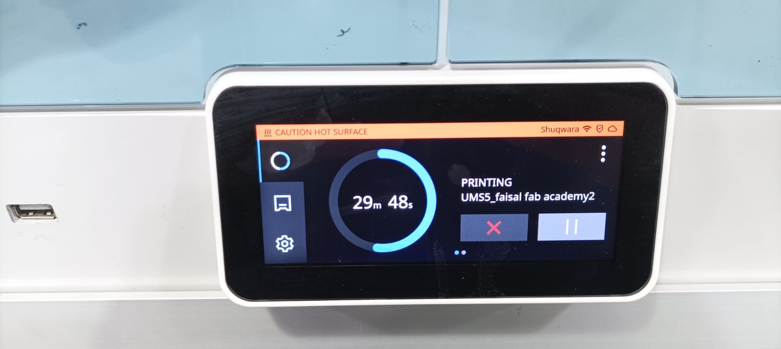
For our test, we sliced a design using Ultimaker Cura slicer software, tweaking settings like resolution and infill density. Then, we loaded up some PLA filament, prepped the printer bed, and got printing. The process was pretty straightforward, just a matter of selecting the file and hitting print.
Now, onto the results. Overall, the printer did a solid job. Overhangs and bridges turned out pretty well, though we did notice some slight inconsistencies in fine details. Nothing major, but it reminded us that precision in design is key for getting the best prints.
In the end, we came away impressed with the Ultimaker S5. It's a reliable workhorse that can handle a wide range of printing tasks. With a bit of tweaking and attention to detail, you can get some really impressive results out of it.
Individual assignment
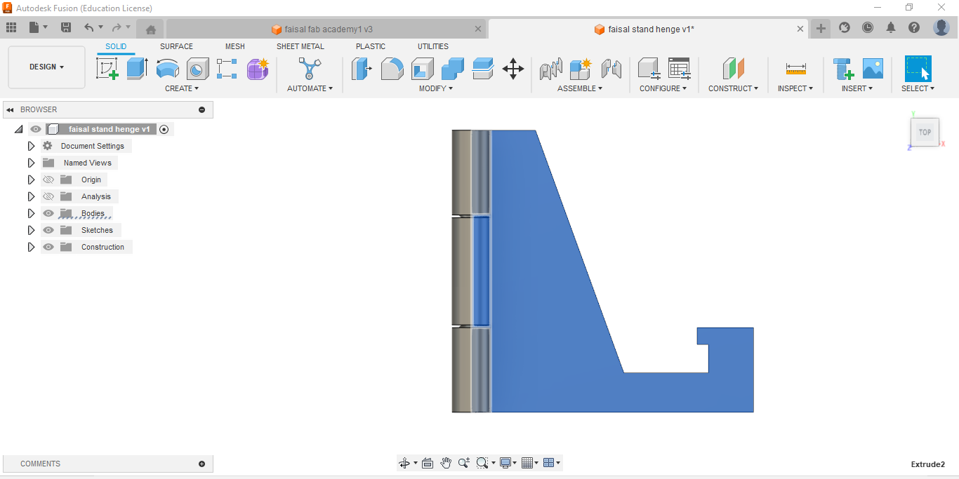
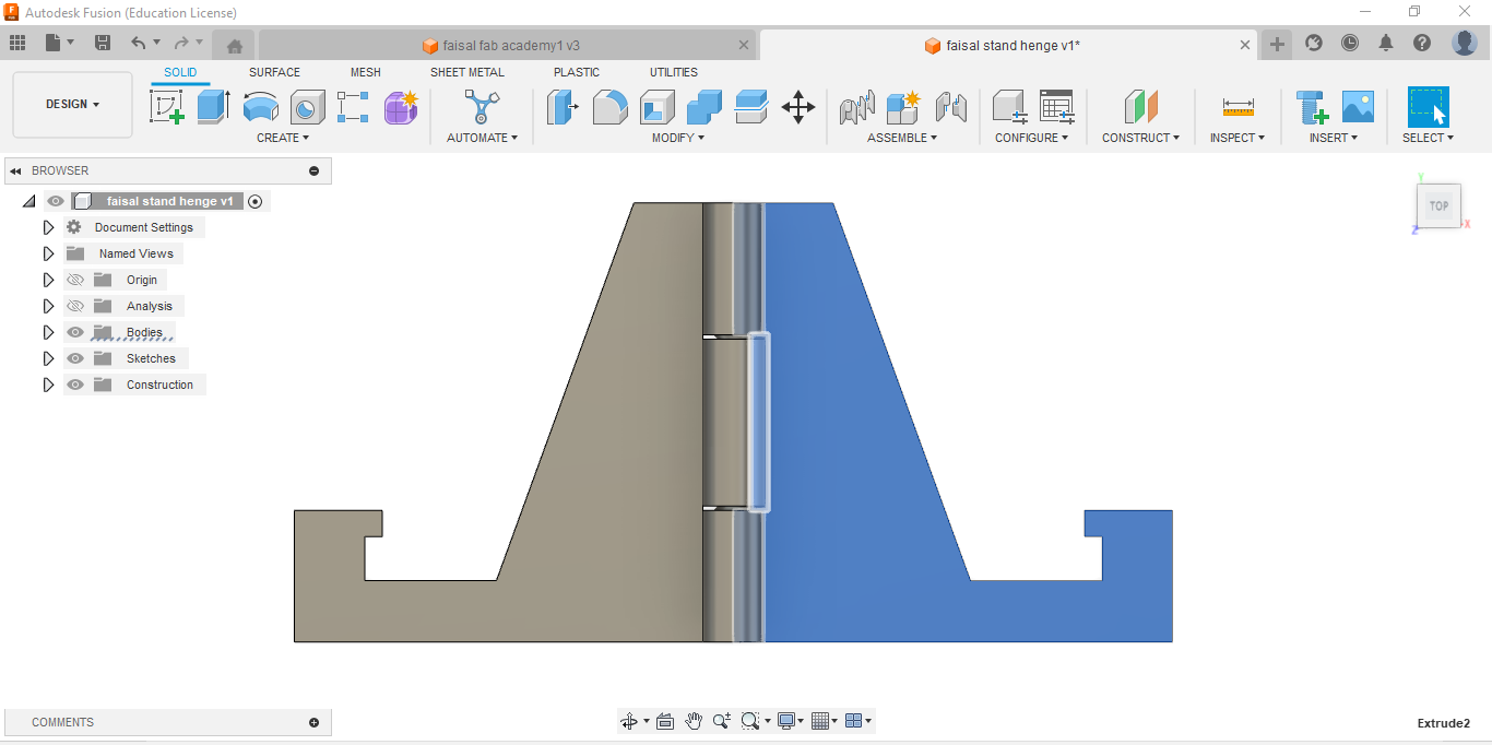
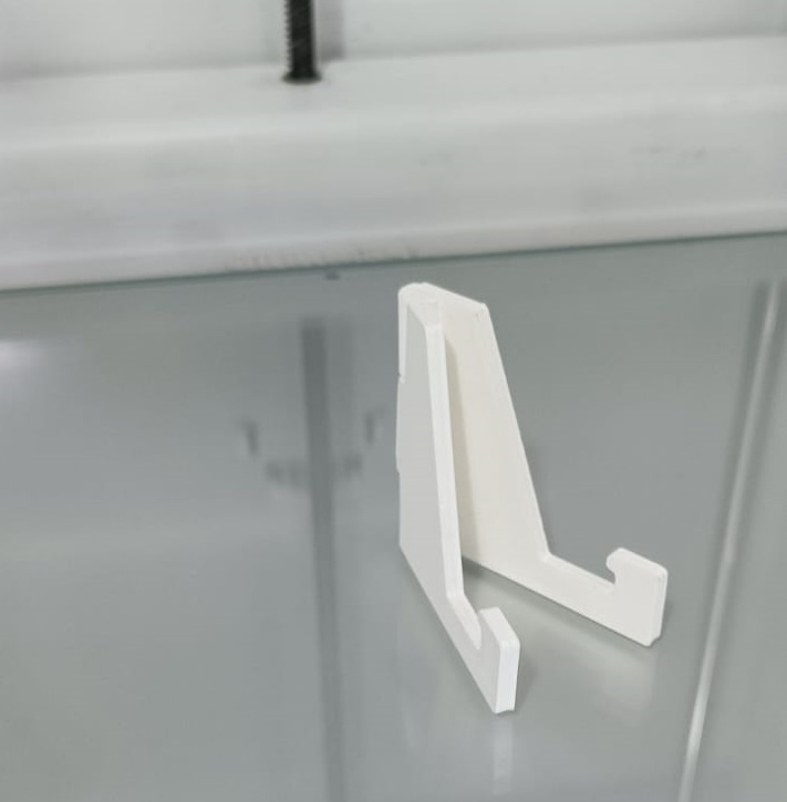
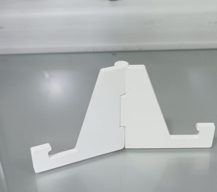
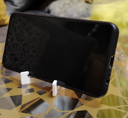
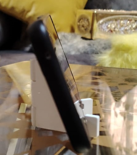
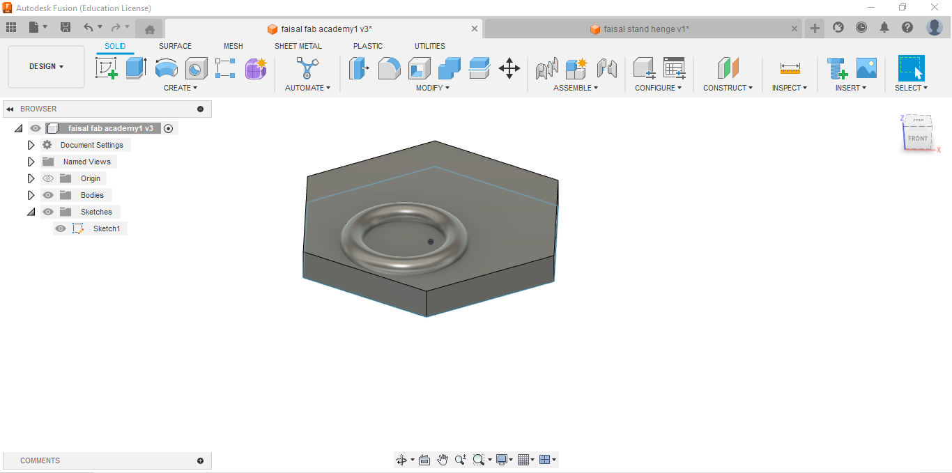
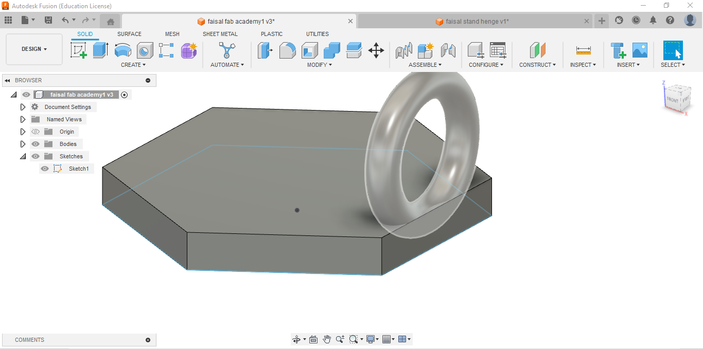
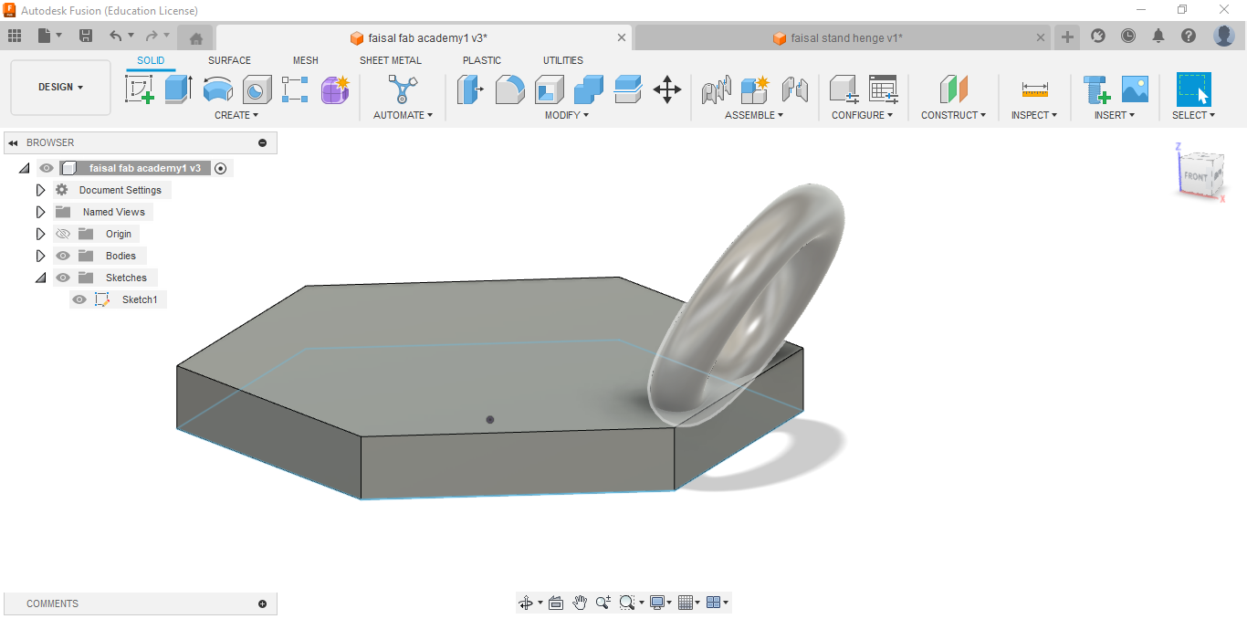
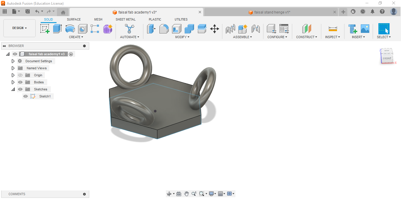
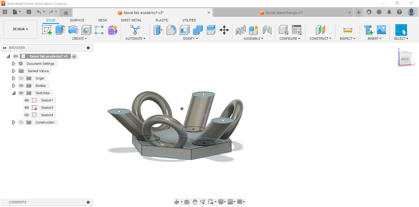
For my individual assignment for this week I made some designs. First I tried to make stand for my phone to ease watching and filming my self , so I tried to make something in one print without assembling more than one part.
Creating a stand with a hinge for a phone using Fusion 360 involves several steps. Here's a basic guide to get you started:
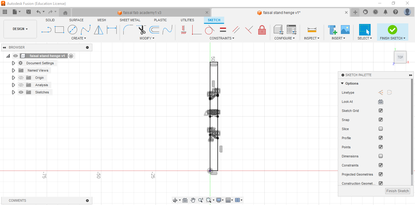
Sketching the Design:
- Open Fusion 360 and create a new design.
- Start by sketching the basic shape of your stand. This could be a simple rectangle or any shape you prefer.
- Use dimensions to define the size of your stand. Consider the dimensions of your phone and ensure the stand provides adequate support.
- Sketch the hinge mechanism. You can use arcs, lines, and other sketch tools to create the hinge parts.
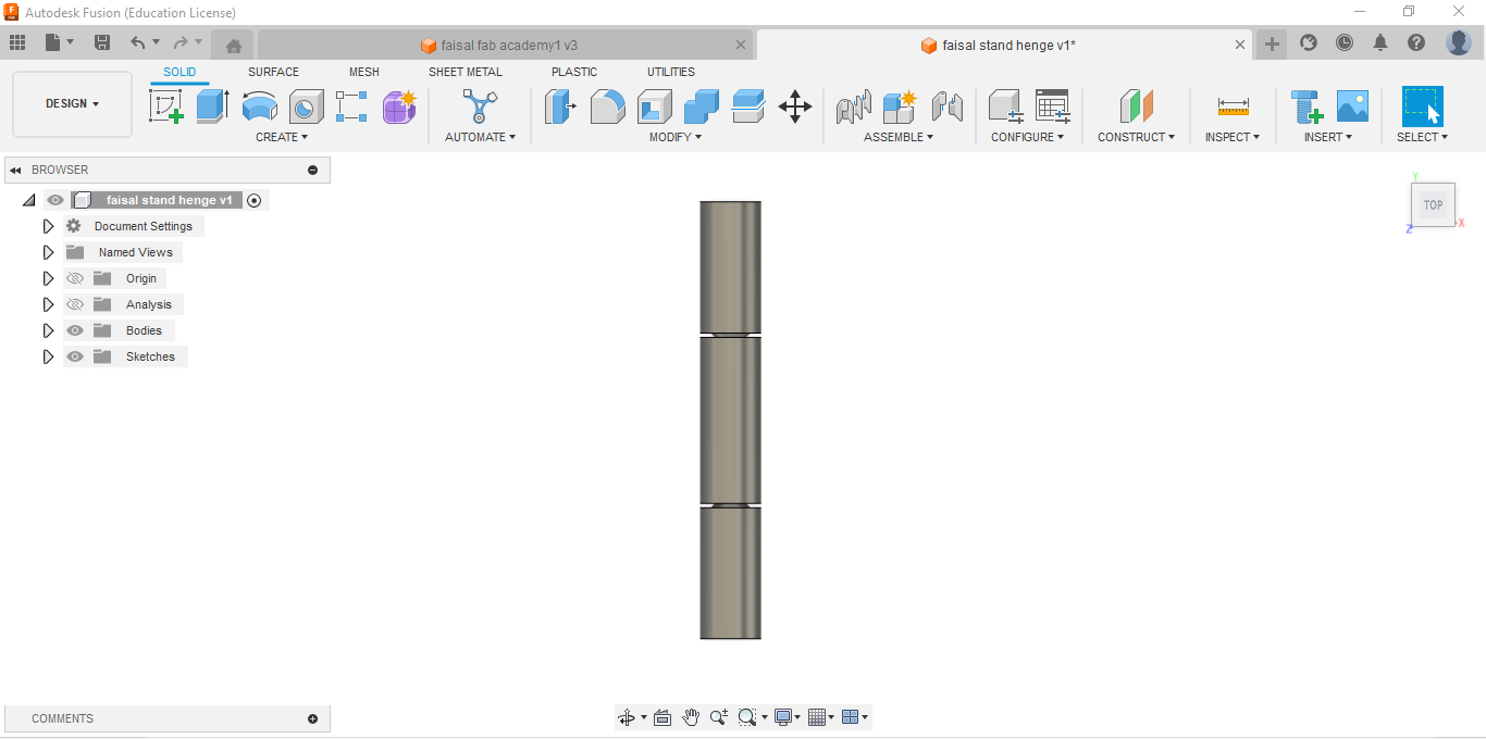
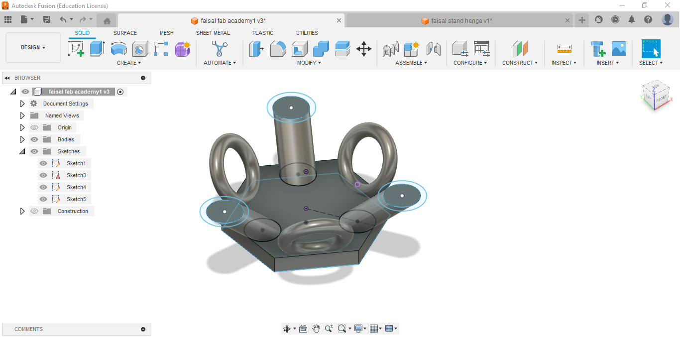
Extrude the Sketches:
- Once your sketches are complete, extrude them to give them depth and create the 3D model of your stand and hinge parts.
- Select the sketches you want to extrude, specify the distance, and click OK to create the extrusions.
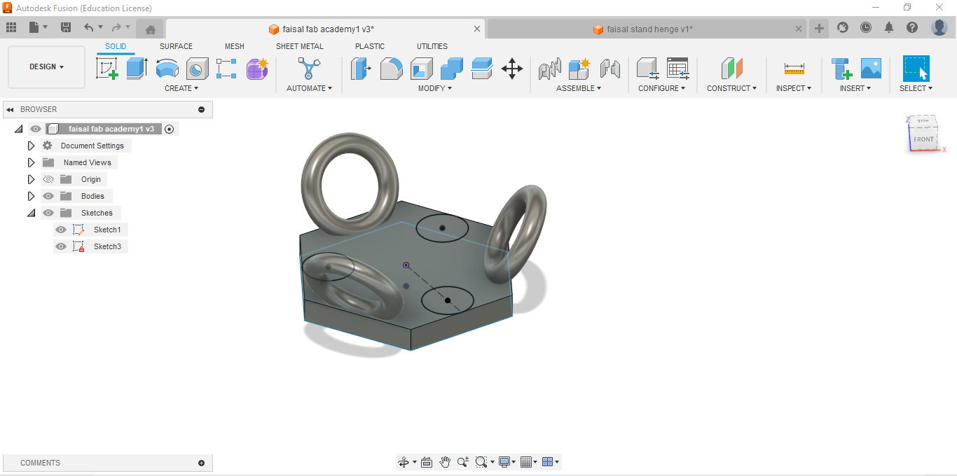
Add Joints for the Hinge:
- Use the Assemble tool to create joints for the hinge mechanism.
- Identify the parts of your hinge that need to move relative to each other.
- Define the joints using the appropriate options in Fusion 360's Assemble menu.
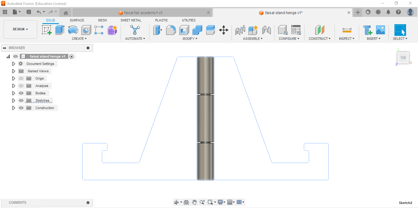
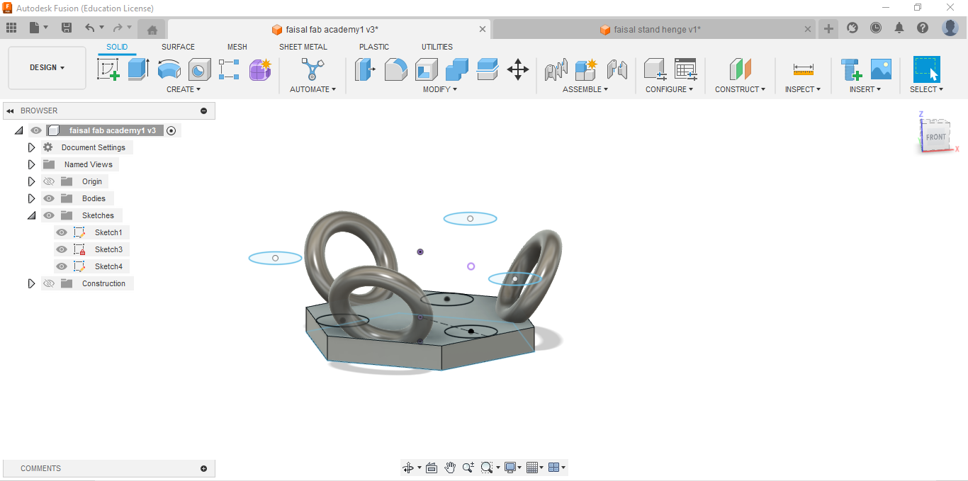
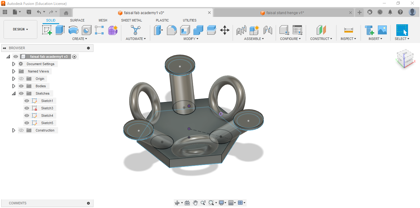
Refine and Adjust:
- Review your design and make any necessary adjustments. This could involve tweaking dimensions, refining the shape, or adjusting the hinge mechanism for better functionality.
- Use Fusion 360's editing tools to modify your design as needed.
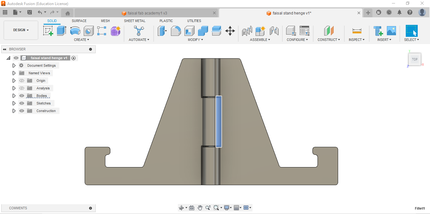
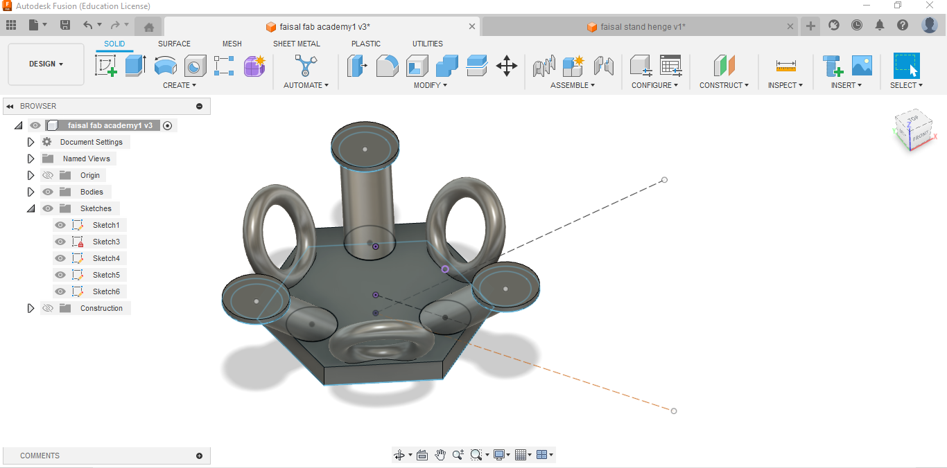
Add Details and Features:
- Consider adding additional features to your stand, such as slots for cables, a textured surface for better grip, or decorative elements.
- Use Fusion 360's sketching and modeling tools to add these details to your design.
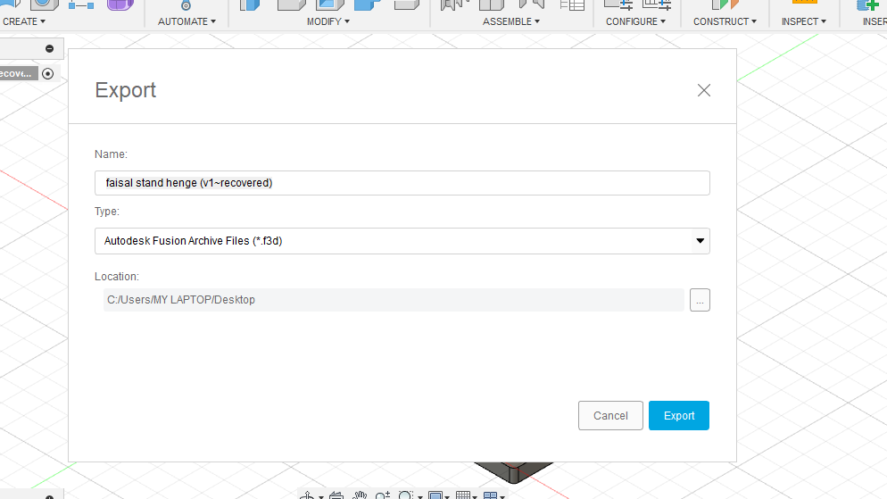
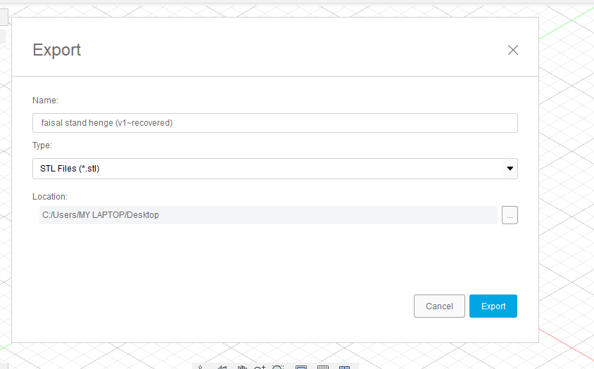
Finalize and Export:
- Once you're satisfied with your design, finalize it by checking for any errors or issues.
- Export your design as an STL file or in a format compatible with your 3D printer.
Print Your Design:
- Use your preferred 3D printing software to prepare your design for printing.
- Select the appropriate print settings, such as layer height and infill density, based on your printer and the requirements of your design.
- Print your design and ensure that the parts fit together correctly and the hinge mechanism functions as intended.
Throughout the process, don't hesitate to experiment and iterate on your design. Fusion 360 offers a wide range of tools and features that allow for creativity and customization in your 3D designs.
And here are my results:
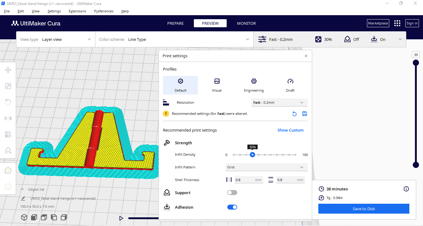
Slicing Steps and Settings for Mobile Stand
Slicing Steps in Cura:
Import the STL File:
- Open Cura slicer and import the STL file of the mobile stand.
Orientation:
- Adjust the orientation of the stand to ensure stability and minimal need for supports.
Scale and Position:
- Ensure the stand is correctly scaled and positioned on the build plate.
Select the Print Profile:
- Choose the standard quality print profile.
Add Supports:
- No supports are needed for this design.
Check Layer View:
- Inspect the slicing in layer view to ensure there are no issues.
Settings Used:
- Layer Height: 0.2 mm (standard quality)
- Infill Density: 30% (for strength and stability)
- Print Speed: 75 mm/s (for faster printing)
- Support: None
- Build Plate Adhesion: Enabled (to ensure good adhesion and prevent warping)
- Material: PLA, 210°C nozzle temperature, 60°C bed temperature
- Retraction Settings: None needed
- Cooling: Enable cooling with fan speed set to 100% after the first few layers
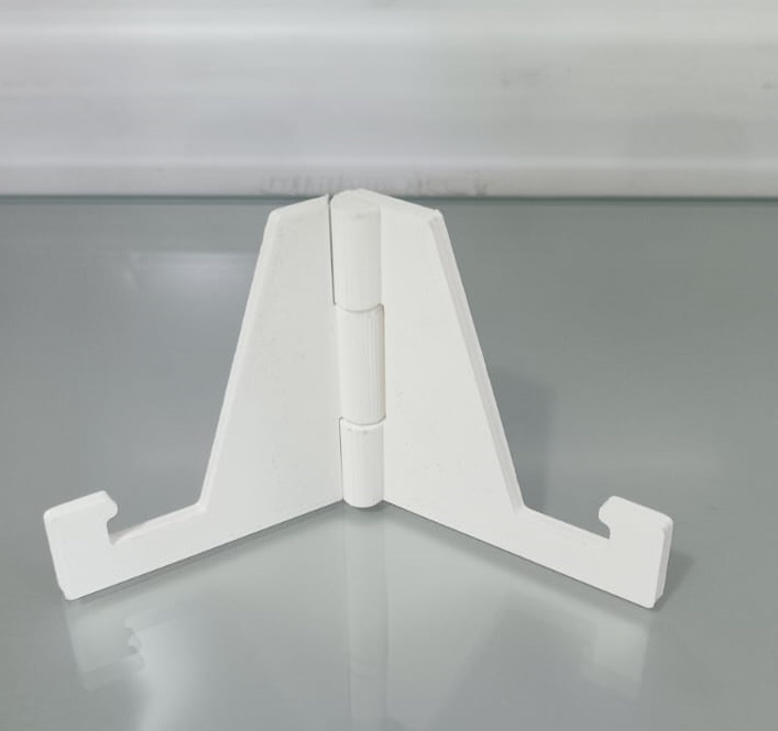
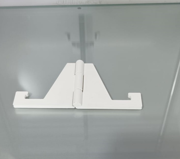

Why the Design Can't Be Done Subtractively
My mobile stand design features complex geometries, such as curved surfaces and integrated compartments, that are difficult to achieve with subtractive methods like milling or machining. These methods would struggle to create the smooth, continuous curves and intricate internal structures of my design without requiring multiple parts and assembly.
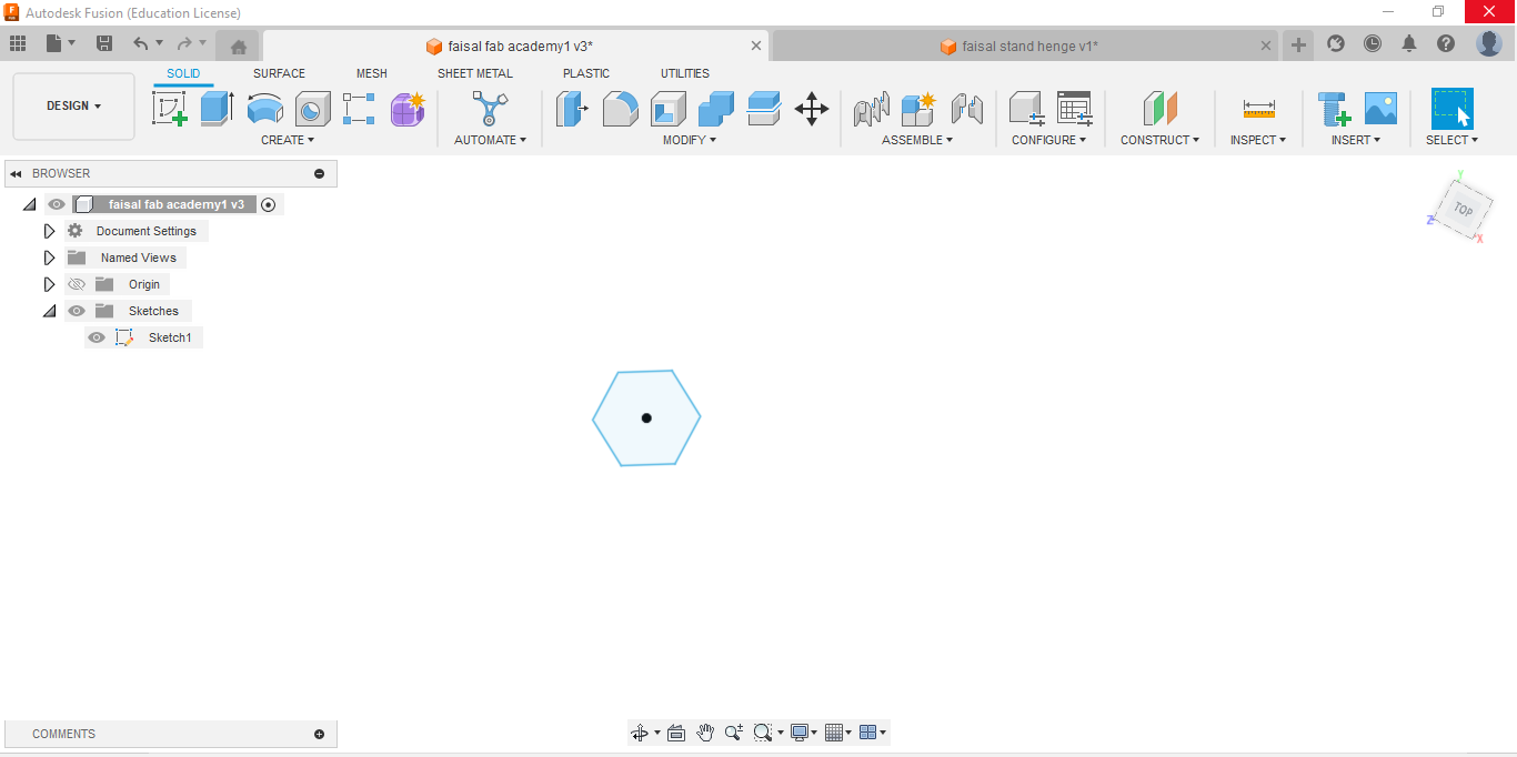
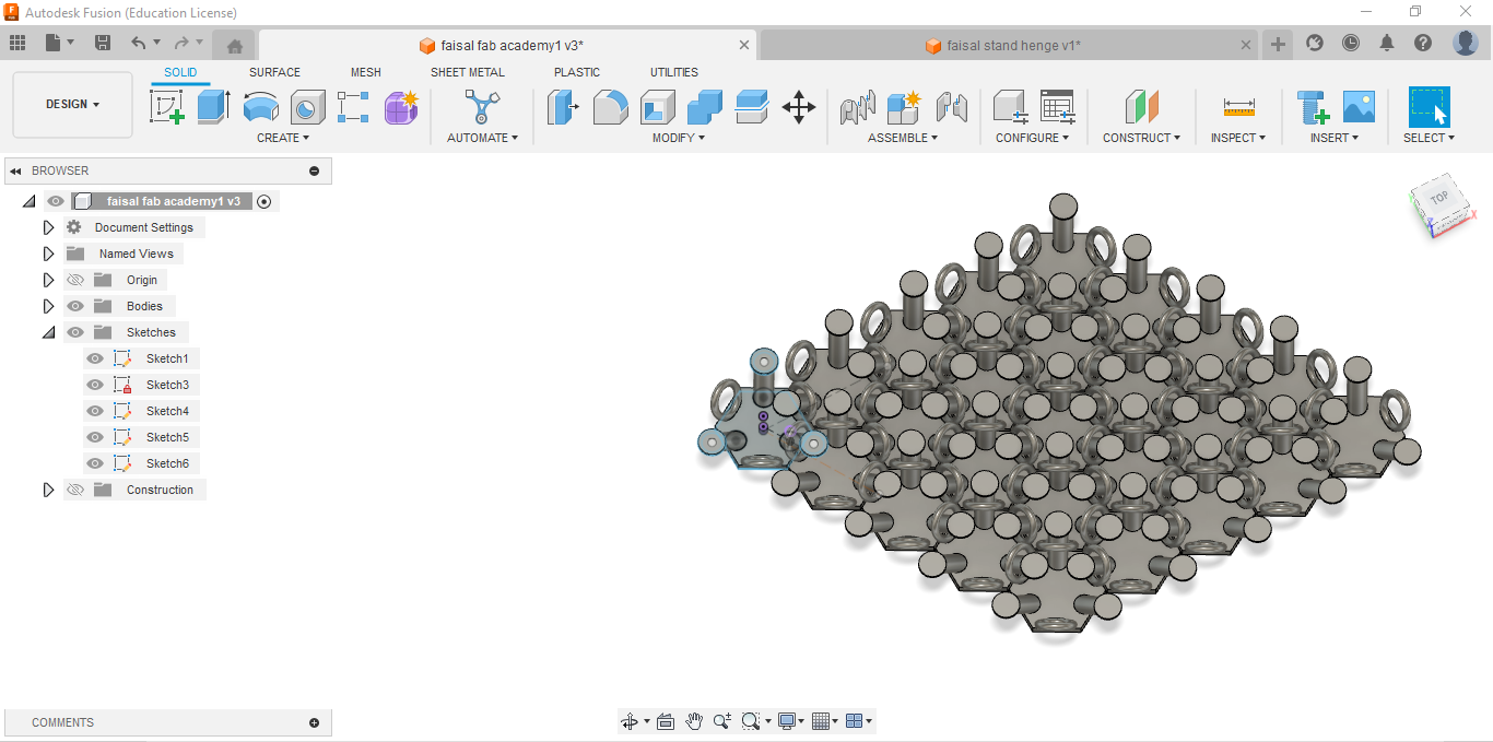
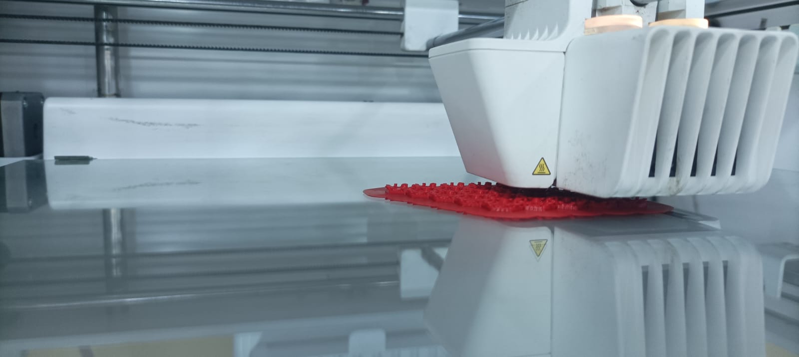
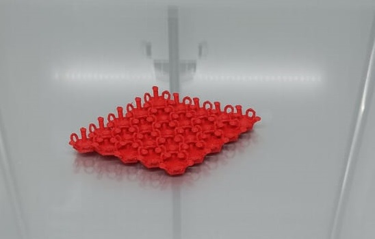
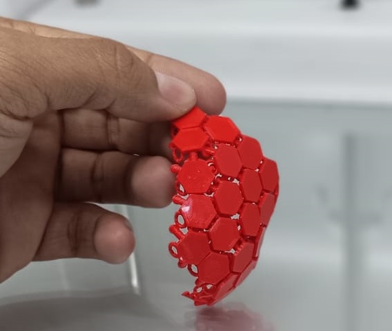
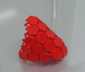
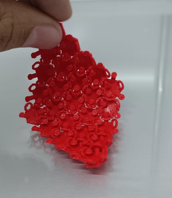
I also tried to do a hex diagonal chainmail.
Creating hexagonal diagonal chainmail in Fusion 360 involves a combination of sketching, patterning, and extruding. Here's a step-by-step guide to help you get started:
Create a New Design:
- Open Fusion 360 and create a new design file to begin your project.
Sketch the Hexagonal Shape:
- Start by sketching a single hexagon shape. Use the sketch tools in Fusion 360 to draw a regular hexagon. You can use the Polygon tool and specify six sides to create the hexagon.
Create the Diagonal Link:
- Sketch a diagonal line from one corner of the hexagon to the opposite corner. This line will represent the link between the hexagons in your chainmail pattern.
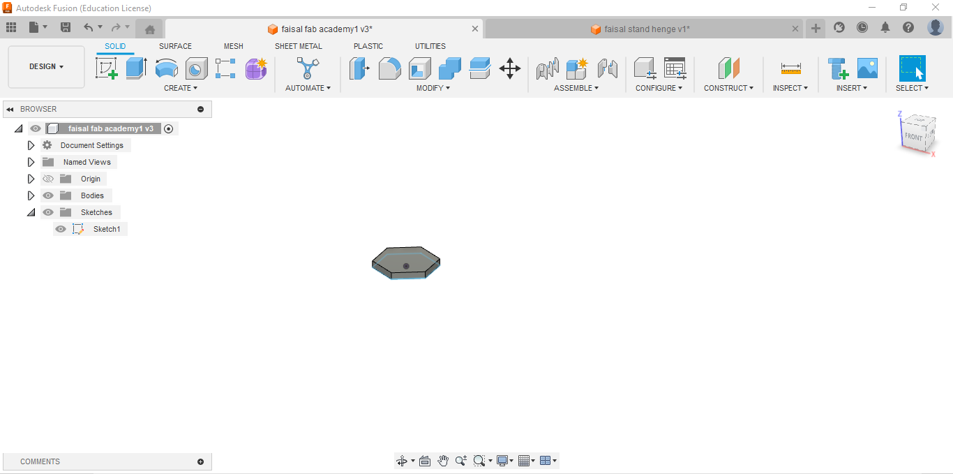
Extrude the Sketch:
- Select the sketch of the hexagon and the diagonal line.
- Use the Extrude command to give your sketch depth. Specify the thickness of your chainmail link by entering the desired extrusion distance.
Pattern the Link:
- Use the Circular Pattern tool to create multiple copies of the link around the center of the hexagon.
- Specify the number of instances and the angle of rotation to create a circular pattern of links.
Repeat for Adjacent Hexagons:
- Repeat the process to create additional hexagons with diagonal links.
- Ensure that the diagonal links align with the adjacent hexagons to create a continuous chainmail pattern.
Refine and Adjust:
- Review your design and make any necessary adjustments to ensure that the chainmail pattern is consistent and aligned correctly.
- Use Fusion 360's editing tools to modify the dimensions, angles, or positions of the hexagons and links as needed.
Add Details (Optional):
- Consider adding additional details to your chainmail design, such as rivets, textures, or variations in thickness.
- Use Fusion 360's sketching and modeling tools to add these details to your design.
Finalize and Export:
- Once you're satisfied with your chainmail design, finalize it by checking for any errors or issues.
- Export your design as an STL file or in a format compatible with your 3D printer.
Print Your Design:
- Prepare your design for 3D printing using your preferred slicing software.
- Adjust printing settings such as layer height and infill density based on your printer and the requirements of your design.
- Print your chainmail design and ensure that the links fit together correctly and create the desired pattern.
By following these steps, you can create hexagonal diagonal chainmail patterns in Fusion 360 and bring your designs to life using 3D printing technology.
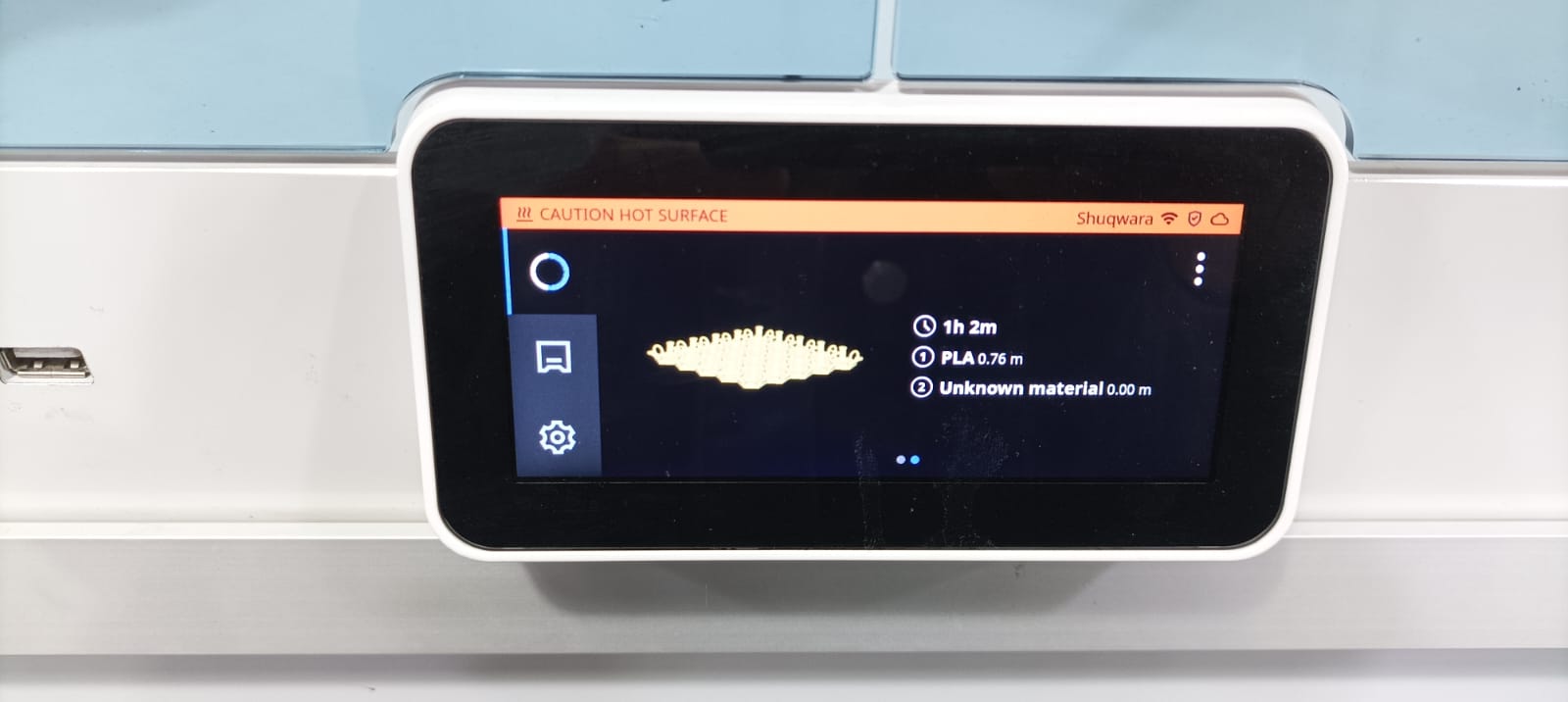
Slicing Steps and Settings for Hexadiagonal Chain Mail
Slicing Steps in Cura:
Import the STL File:
- Open Cura slicer and import the STL file of the hexadiagonal chain mail.
Orientation:
- Lay the chain mail flat to maintain the integrity of the links and flexibility.
Scale and Position:
- Ensure the chain mail is correctly scaled and positioned on the build plate.
Select the Print Profile:
- Choose the standard quality print profile.
Add Supports:
- No supports are needed for this design.
Check Layer View:
- Inspect the slicing in layer view to ensure there are no issues.
- Layer Height: 0.2 mm (standard quality)
- Infill Density: 30% (to maintain flexibility while providing enough support)
- Print Speed: 75 mm/s (for faster printing)
- Support: None
- Build Plate Adhesion: Enabled (to ensure good adhesion and prevent warping)
- Material: PLA, 210°C nozzle temperature, 60°C bed temperature
- Retraction Settings: None needed
- Cooling: Enable cooling with fan speed set to 100% after the first few layers
Why the Design Can't Be Done Subtractively
The hexadiagonal chain mail design consists of interlocking hexagonal rings that are nearly impossible to produce subtractively. Each link interlocks with others in a way that can't be machined or cut from a single piece of material without disassembly and reassembly. The flexibility and detailed connections of the chain mail are best achieved through additive manufacturing, where the links can be printed together in their final form.
Advantages of Ultimaker S5 3D Printer:
Large Build Volume:
- The Ultimaker S5 offers a generous build volume of 330 x 240 x 300 mm, allowing for the creation of large prints or multiple smaller parts simultaneously.
Dual Extrusion:
- It features a dual extrusion system, enabling multi-material printing, including support for PVA water-soluble support material, which is great for complex geometries.
Touchscreen Interface:
- The intuitive touchscreen interface makes it easy to navigate settings and monitor print progress.
High-Resolution Printing:
- It offers high-resolution printing capabilities, providing fine details and smooth surface finishes.
Compatibility with Various Materials:
- The Ultimaker S5 is compatible with a wide range of materials, including PLA, ABS, Nylon, TPU, and composites like carbon fiber and glass fiber reinforced filaments.
Active Bed Leveling:
- The active bed leveling ensures a perfect first layer, enhancing print quality and reliability.
Enclosed Build Chamber:
- The enclosed build chamber maintains a stable print environment, reducing the chances of warping and improving print quality.
Filament Flow Sensor:
- The filament flow sensor detects when the filament runs out or is jammed, pausing the print to prevent failures.
Integration with Cura:
- Seamless integration with Ultimaker’s Cura slicer software offers advanced slicing features and optimized print profiles.
Limitations of Ultimaker S5 3D Printer:
High Cost:
- The Ultimaker S5 is relatively expensive, making it less accessible for hobbyists and small businesses with limited budgets.
Speed:
- While it provides high-quality prints, the printing speed can be slower compared to other industrial-grade 3D printers.
Size and Weight:
- The printer is large and heavy, requiring significant space and a sturdy surface for setup and operation.
Limited Heated Bed Temperature:
- The heated bed has a maximum temperature of 140°C, which might not be sufficient for certain high-temperature filaments.
Noise Level:
- The Ultimaker S5 can be noisy during operation, which may be a concern in noise-sensitive environments.
Learning Curve:
- While it’s user-friendly, there can still be a learning curve for beginners, especially when dealing with dual extrusion and advanced material settings.
Maintenance:
- Regular maintenance, including nozzle cleaning and bed leveling checks, is required to ensure optimal performance.
Limited to FDM Technology:
- As an FDM printer, it may not achieve the same level of detail and surface finish as SLA or SLS printers for certain applications.
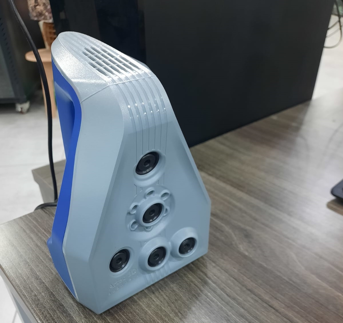
3d scanning
There are a lot of applications and softwares that could be used to 3D scan objects, one of them is Artec Studio 17
Artec Studio 17 is a professional 3D scanning software developed by Artec 3D. It's designed to work seamlessly with Artec 3D scanners to capture and process high-quality 3D models. Here's a basic guide on how to use Artec Studio 17 to scan objects:
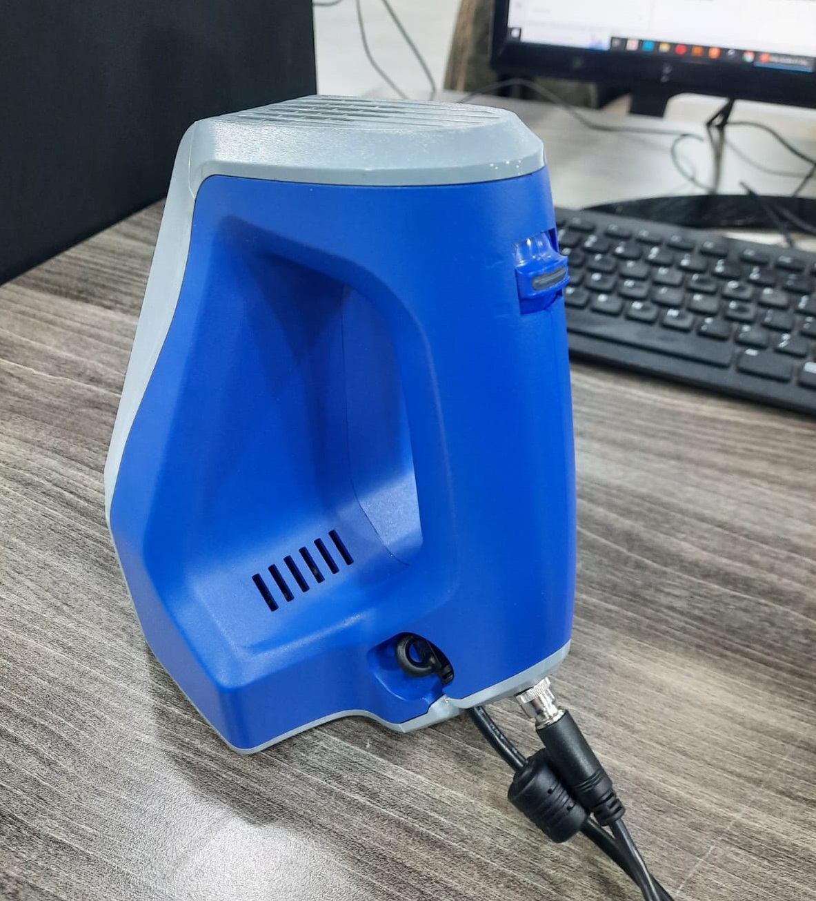
Set up Your Scanner:
- Before you start scanning, ensure that your Artec 3D scanner is properly set up and connected to your computer according to the manufacturer's instructions.
- Make sure the scanner is calibrated for optimal performance.
Launch Artec Studio 17:
- Open the Artec Studio 17 software on your computer.
Choose Scan Mode:
- In Artec Studio 17, you have several scan modes to choose from, such as "Texture," "Geometry," and "Color."
- Select the appropriate scan mode based on the characteristics of the object you're scanning and the level of detail you require.
Prepare Your Object:
- Place the object you want to scan on a stable surface in a well-lit environment.
- Ensure that the object is positioned in such a way that the scanner can capture all desired angles and details.
Start the Scan:
- In Artec Studio 17, initiate the scanning process by selecting the appropriate options in the interface.
- Follow the on-screen prompts to guide the scanning process. This may involve moving the scanner around the object to capture it from different angles.
- Aim to cover the entire surface of the object with the scanner to ensure complete coverage.
Monitor the Scanning Progress:
- As you scan, monitor the progress in Artec Studio 17's viewport. You should see the scanned data appearing in real-time.
Capture Additional Scans (if needed):
- Depending on the complexity and size of the object, you may need to capture multiple scans from different angles to ensure full coverage.
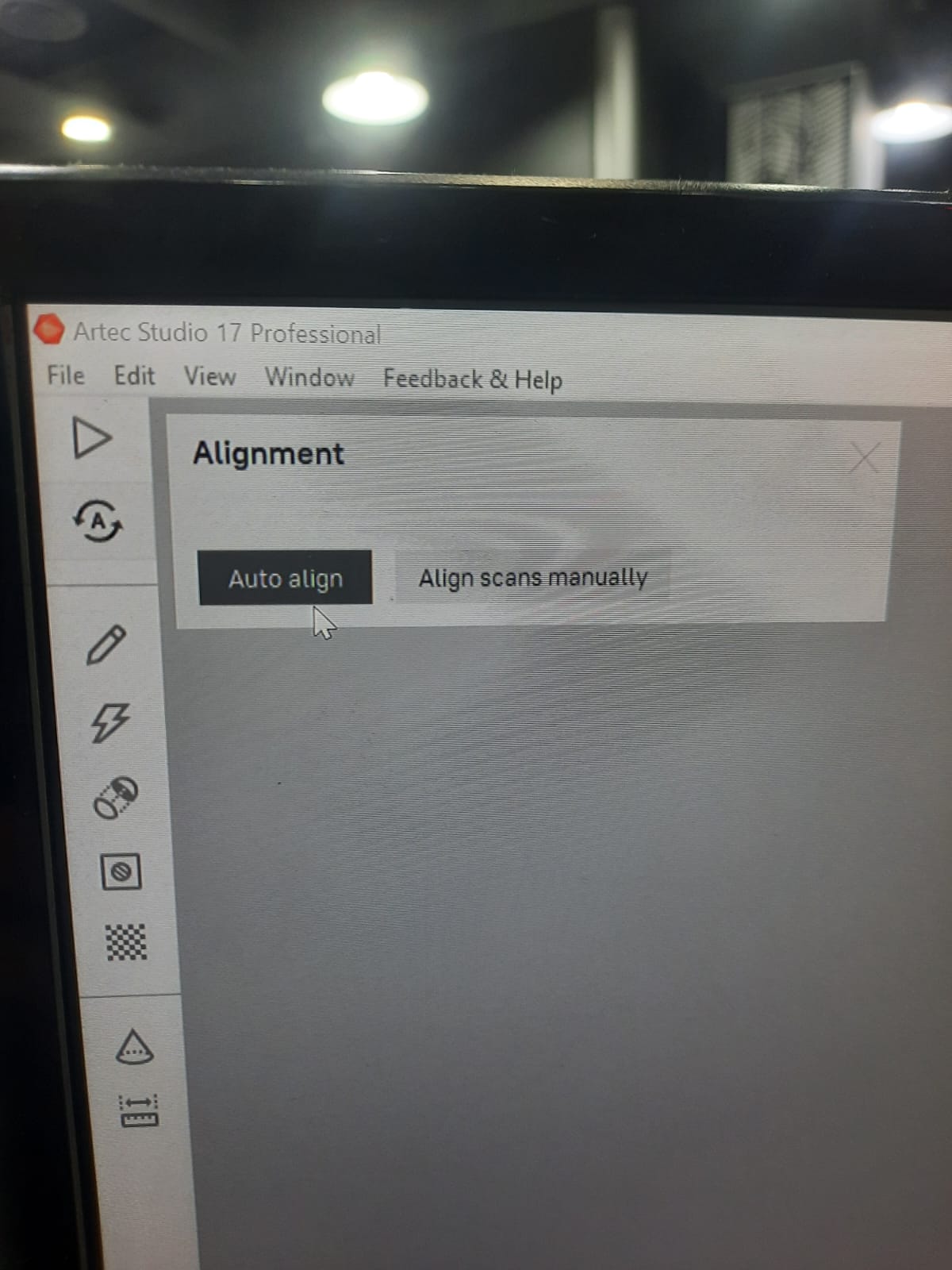
- Use Artec Studio 17's alignment tools to merge multiple scans into a single cohesive model.
Process the Scanned Data:
- Once you've completed the scanning process, use Artec Studio 17's editing and processing tools to refine the scanned data.
- This may include cleaning up noise, aligning multiple scans, filling in gaps, and optimizing the mesh.
Export the 3D Model:
- Once you're satisfied with the scanned and processed data, export the 3D model in the desired file format.
- Artec Studio 17 supports various file formats suitable for 3D printing, CAD modeling, and visualization.
Save Your Project:
- It's a good practice to save your Artec Studio 17 project file (.pzf) so that you can revisit and edit it later if needed.
By following these steps, you can effectively use Artec Studio 17 to scan objects and create high-quality 3D models for various applications.
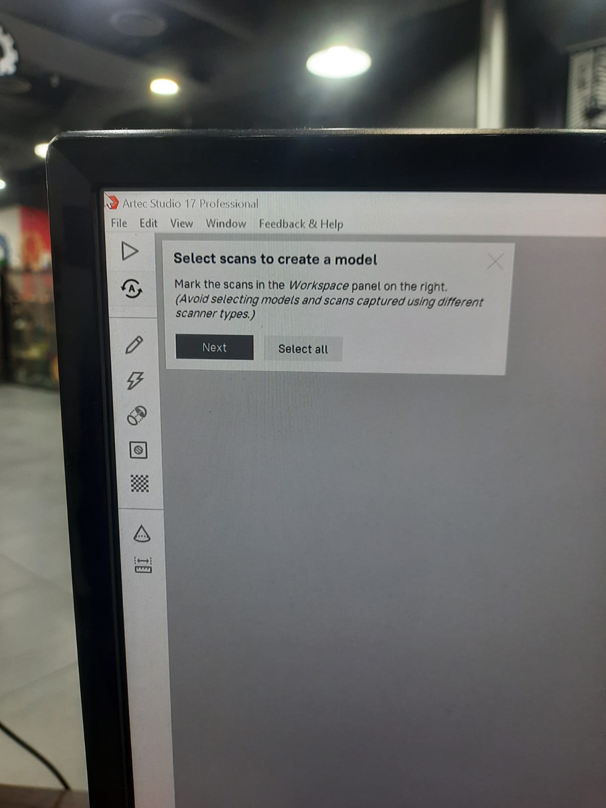
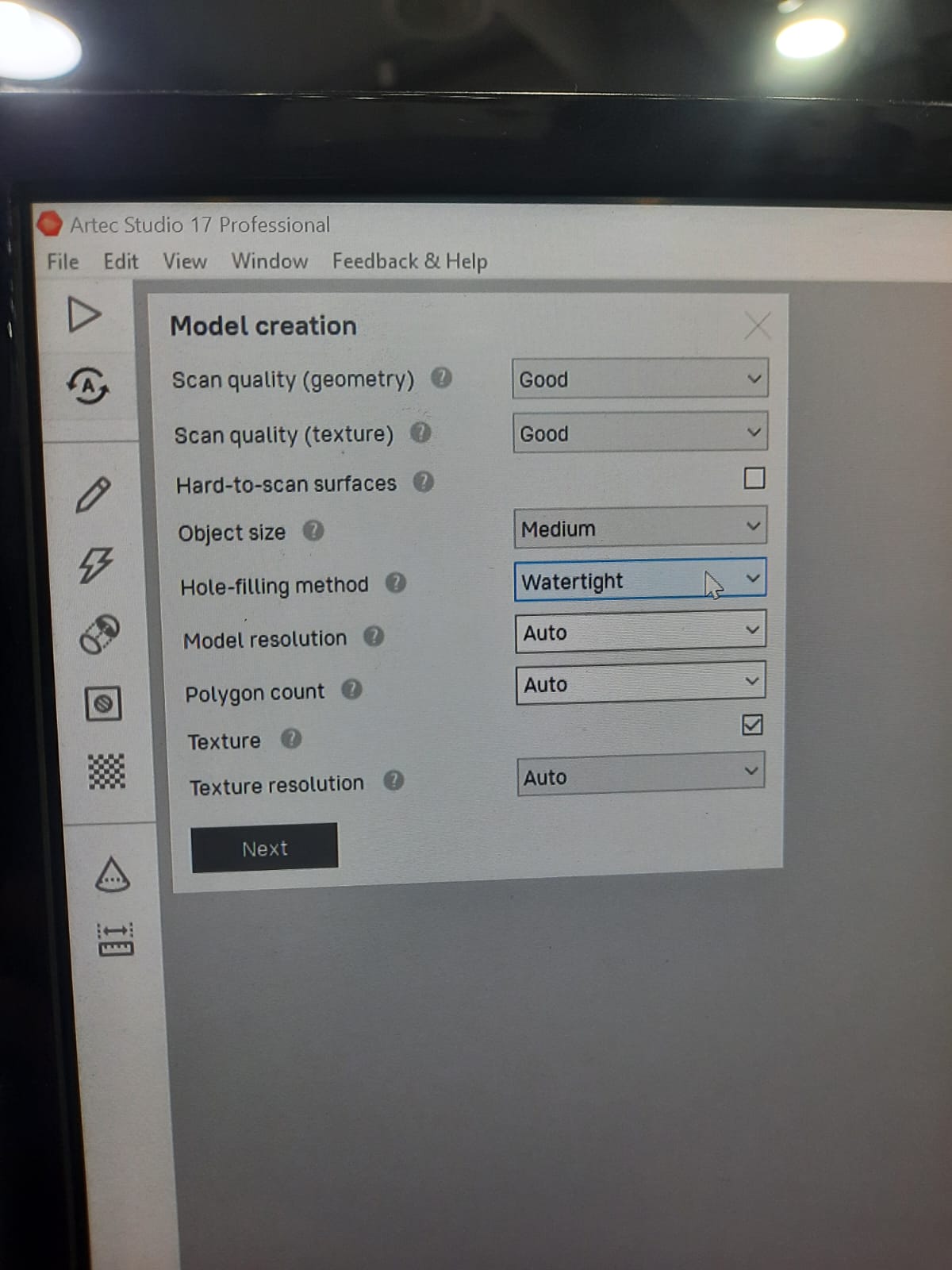
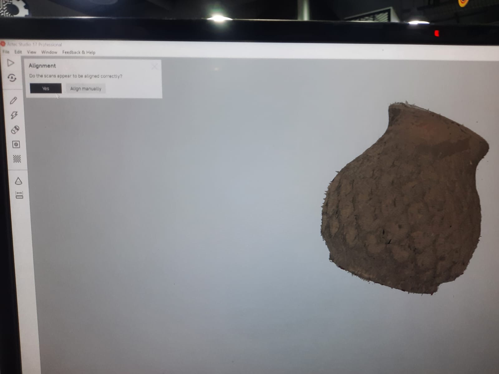
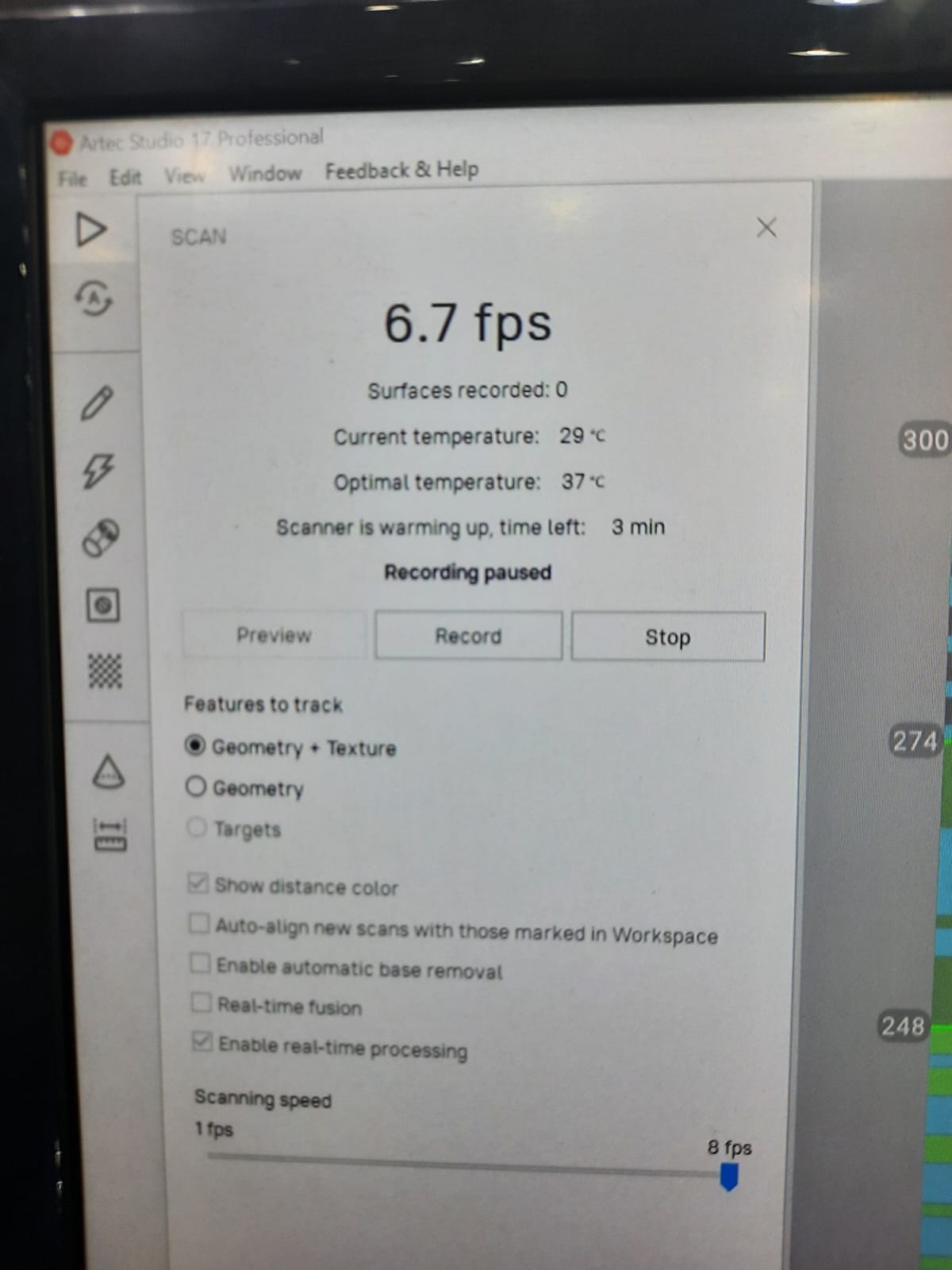
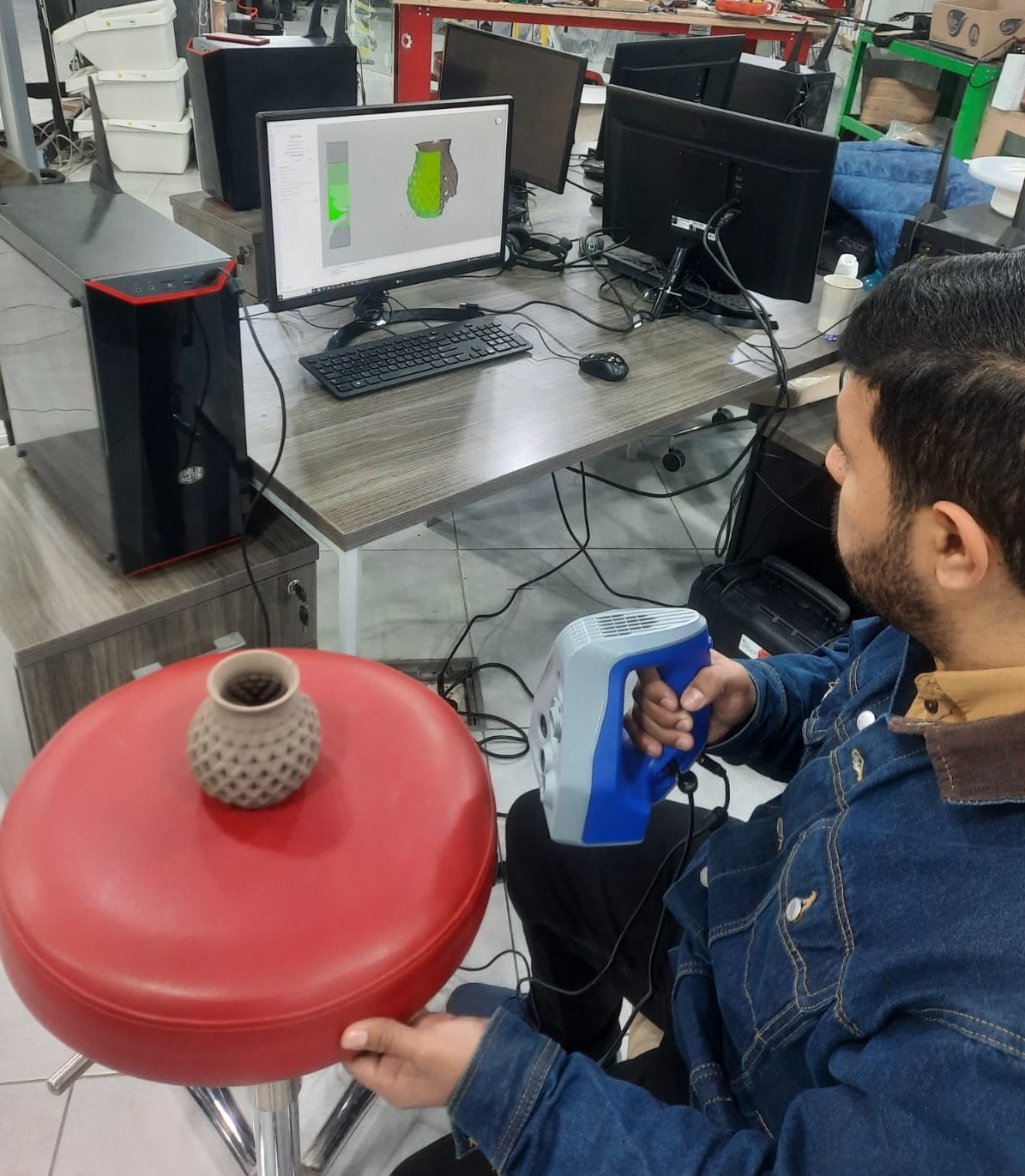
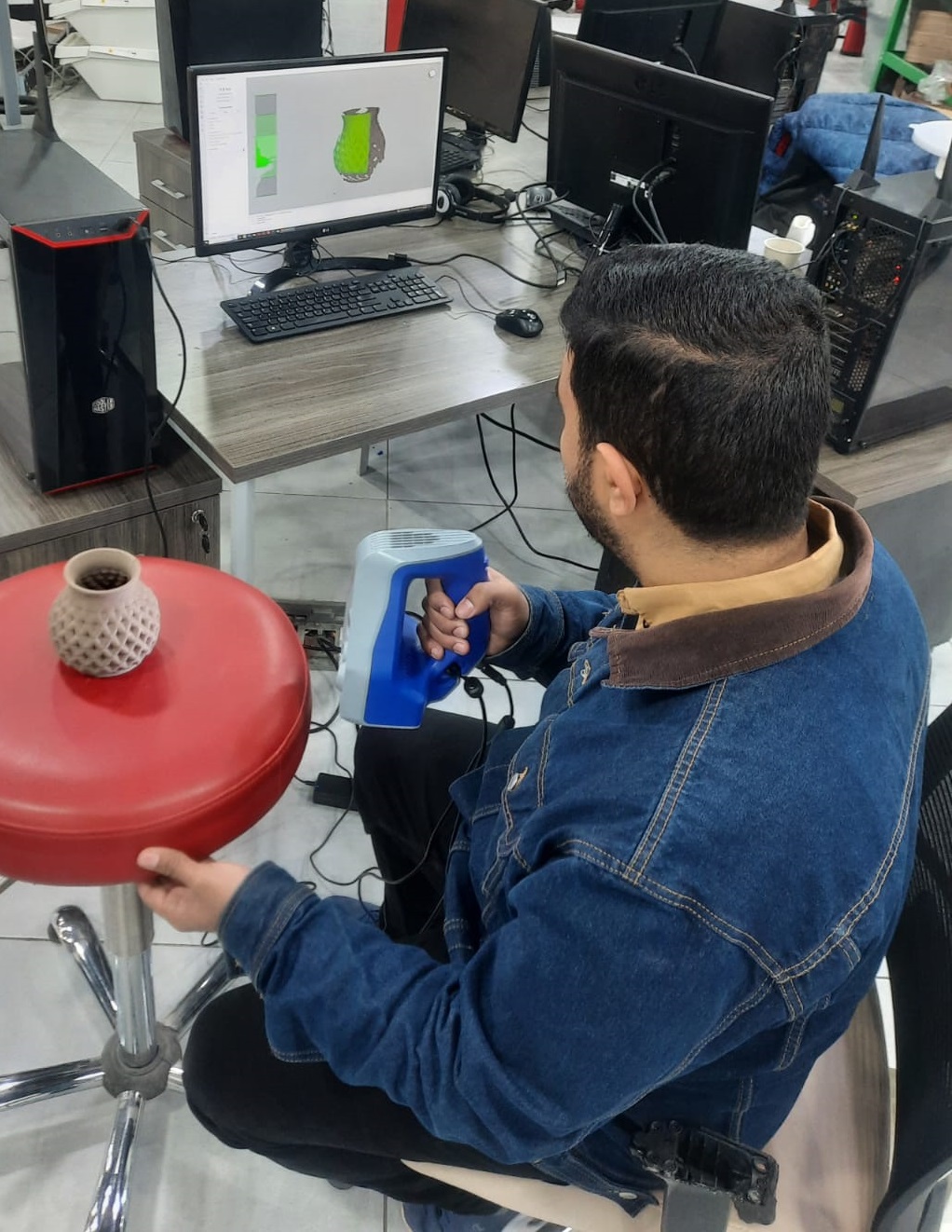
Here when you open the program these are the settings and the situation of the scanner.
Here I started to scan the object by moving the chair and tracking the green area to be sure that the scanner is scanning well.
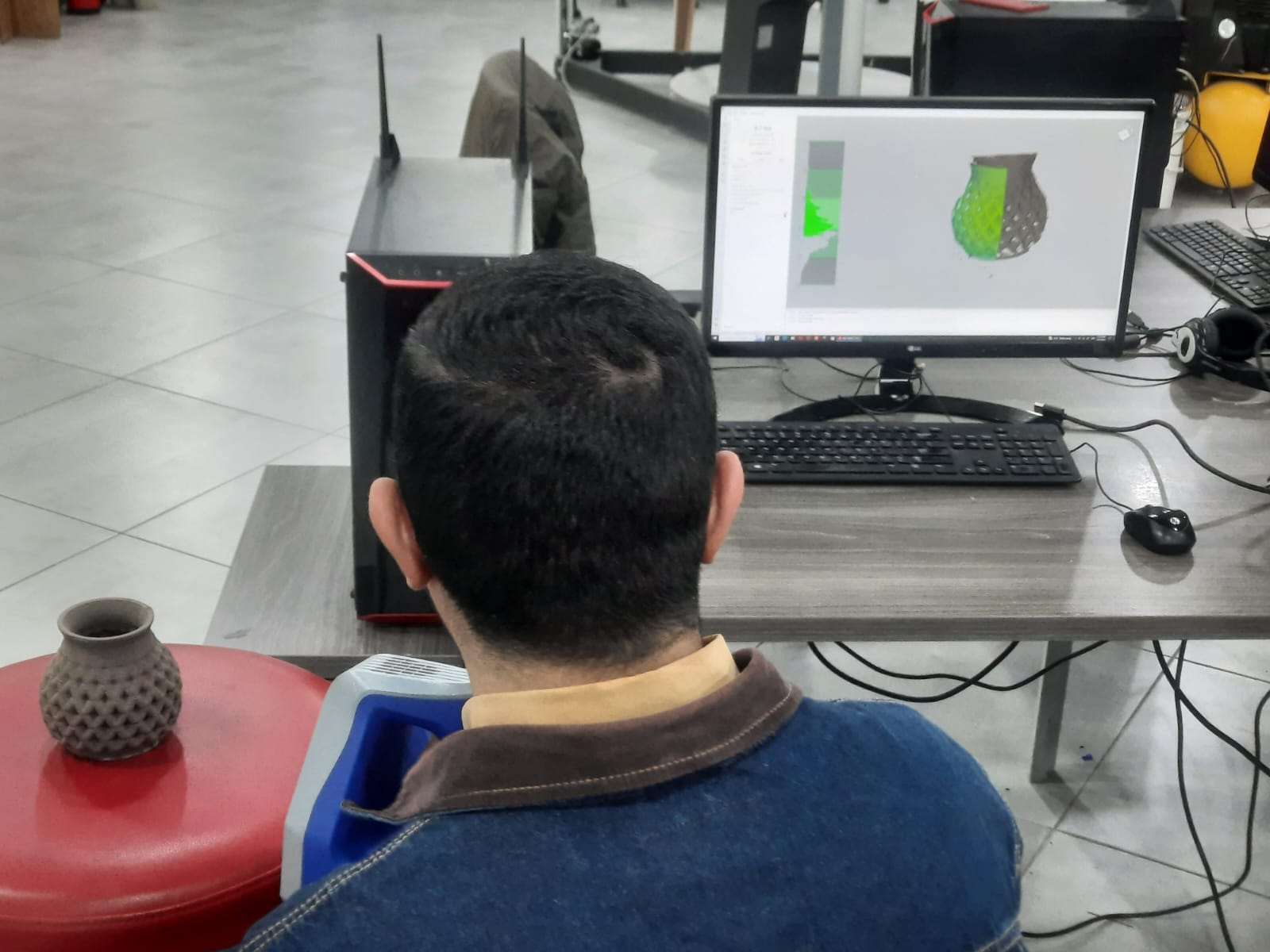
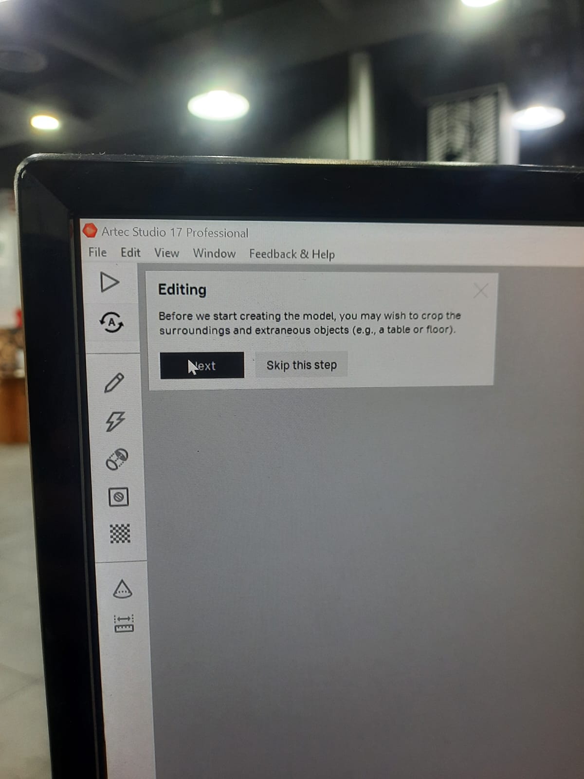
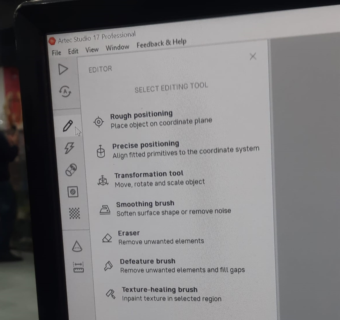
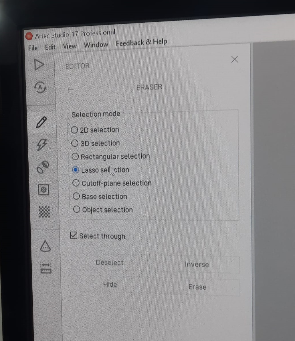
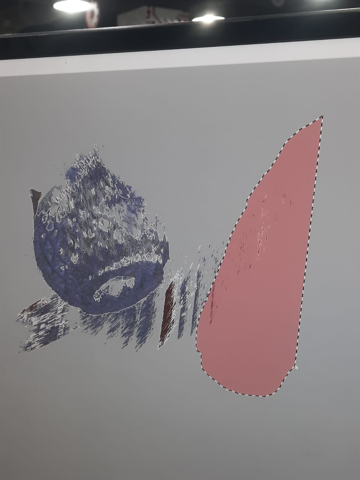
When I ensure that my scan is good I went to the editor to remove unnecessary parts.
Once I ensure that the scan is good and the model is ready here I started to extract the stl file.