Computer controlled machining
Welcome to this week's documentary as we take a deep dive into computer-controlled machining and delve into the intricacies of CNC milling operations, safety protocols, material testing, and toolpath generation to achieve precise machining results using our Shopbot CNC mills.
Learning Outcomes:
- Demonstrate 2D design development for CNC milling production
- Describe workflows for CNC milling production
In completing the group assignment on computer-controlled machining, we focused on several key aspects to ensure safe and efficient operation of the large format CNC router machine. Here's a summary of our process:
This document is a guide to operating a large format CNC router machine. The machine used in this example is a Shopbot with a spindle max speed of 16,500 RPM and a machine bed size of 1220mm x 2400mm. VCarve is the toolpath generation software used.
Safety is the top priority when working with a CNC router. Here are some safety rules:
- Wear eye and ear protection
- No loose clothing or jewelry
- Wear closed-toe shoes
- Use a dust collection system
The machine can cut a variety of materials including MDF, plywood, blockboard, acrylic, and foam. This document focuses on using 18mm plywood and 18mm blockboard.
Here are the steps to fixturing the material:
- Drill pilot holes
- Attach screws
After securing the material, here are the steps to machine setup:
- Replace the bit
- Zero the Axis
VCarve is used to generate the toolpath. Here are the steps involved:
- Set job dimensions
- Create geometry
- Use the array tool to duplicate the geometry
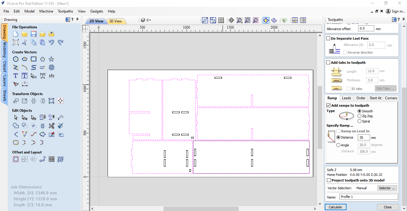
- Create a profile toolpath
- Adjust toolpath settings
- Choose machine vectors
- Specify start depth and cut depth
- Save and export the toolpath
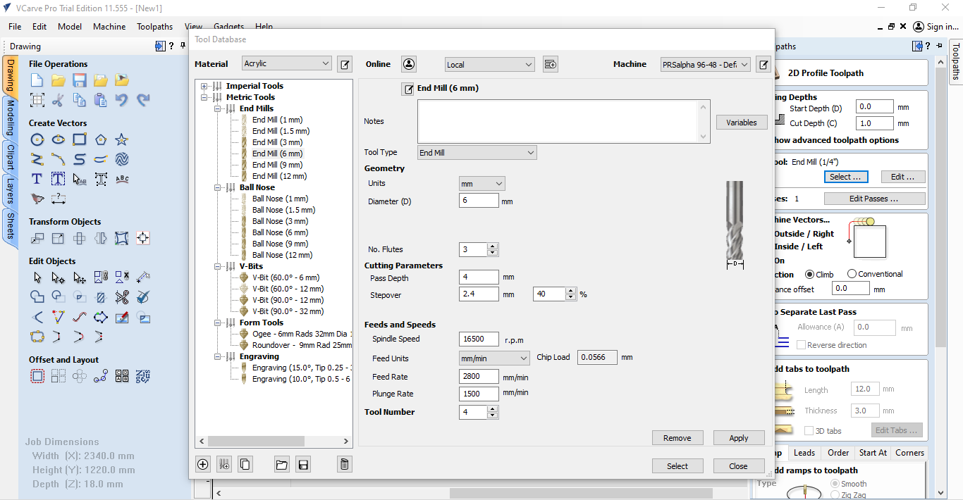
- Feed rate: 2800mm/min
- Spindle speed: 15500rpm
- Plunge rate: 500mm/min
- Pass depth: 3mm
Fswizard.com was used to calculate the optimal speeds and feeds which were 15500 RPM and 2800 mm/min.
The document concludes that the best settings for engraving blockboard to a depth of 6mm with a 6mm bit are:
Runout and alignment were tested by cutting a square and measuring the dimensions. The results showed good alignment and minimal runout.
Individual assignment
This week's session on CNC Machine Router provided me with valuable insights into its operation and capabilities. Here are the key points I learned:
CNC Tool Materials:
High-Speed Steel (HSS): Affordable and durable, suitable for various materials.
Tungsten Carbide (TCT): Extremely hard and heat-resistant, ideal for abrasive materials.
Polycrystalline Diamond (PCD): Exceptionally hard, perfect for clean cuts on abrasive materials.
Ceramic: Heat-resistant, suitable for continuous cutting at high speeds.
Tool Shapes:
Flat End Mill: For general flat surface machining.
Ball Nose End Mill: Creates curved surfaces and profiles.
V-Bit: Ideal for grooves, sharp angles, and lettering.
Form Tool: Customized shapes and profiles.
Upcut vs. Downcut End Mills:
Upcut: Lifts material while cutting, prevents tearing in soft materials, rougher finish on top.
Downcut: Pushes material down while cutting, prevents chipping in hard materials, smoother finish on top.
Up Milling vs. Down Milling:
Up Milling: Cutting against rotation, can cause tool deflection and chipping.
Down Milling: Cutting with rotation, preferred for cleaner cuts and better tool stability.
Important Note:
- Secure the workpiece properly for accurate and safe machining.
Additional Information:
- CNC-related equations involve calculating factors like feed rates, spindle speeds, and chip loads for optimal cutting performance. Specialized software or online tools are often used for these calculations.
About the Tool: 1/26H40 230710FST-FC
This tool is a cutting or milling bit used in CNC machines. Here's the scoop on what its name means:
- 1/2: It’s got a half-inch diameter.
- 6: The cutting part is 6 inches long.
- H40: This means it's really hard, perfect for cutting tougher materials.
- 230710FST-FC: This is just a special code from the manufacturer to help you order the exact same tool again.
What It’s Good For
- Medium to heavy-duty cutting: It's great for taking off a lot of material while still being precise.
- Deep cuts: With a 6-inch cutting length, it’s perfect for deeper cuts.
- Tough materials: The high hardness (H40) makes it ideal for cutting hard stuff like steel.
Where You’d Use It
- Manufacturing: Making parts for cars, planes, and machines.
- Prototyping: Creating new designs where precision matters.
- Metalworking: Cutting through tough metals with ease.
In a nutshell, the 1/26H40 230710FST-FC is a go-to tool for serious machining jobs that need precision and can handle tough materials.
Here is the equations that help us ti specify the settigs of the machine depending on the material that we are using.
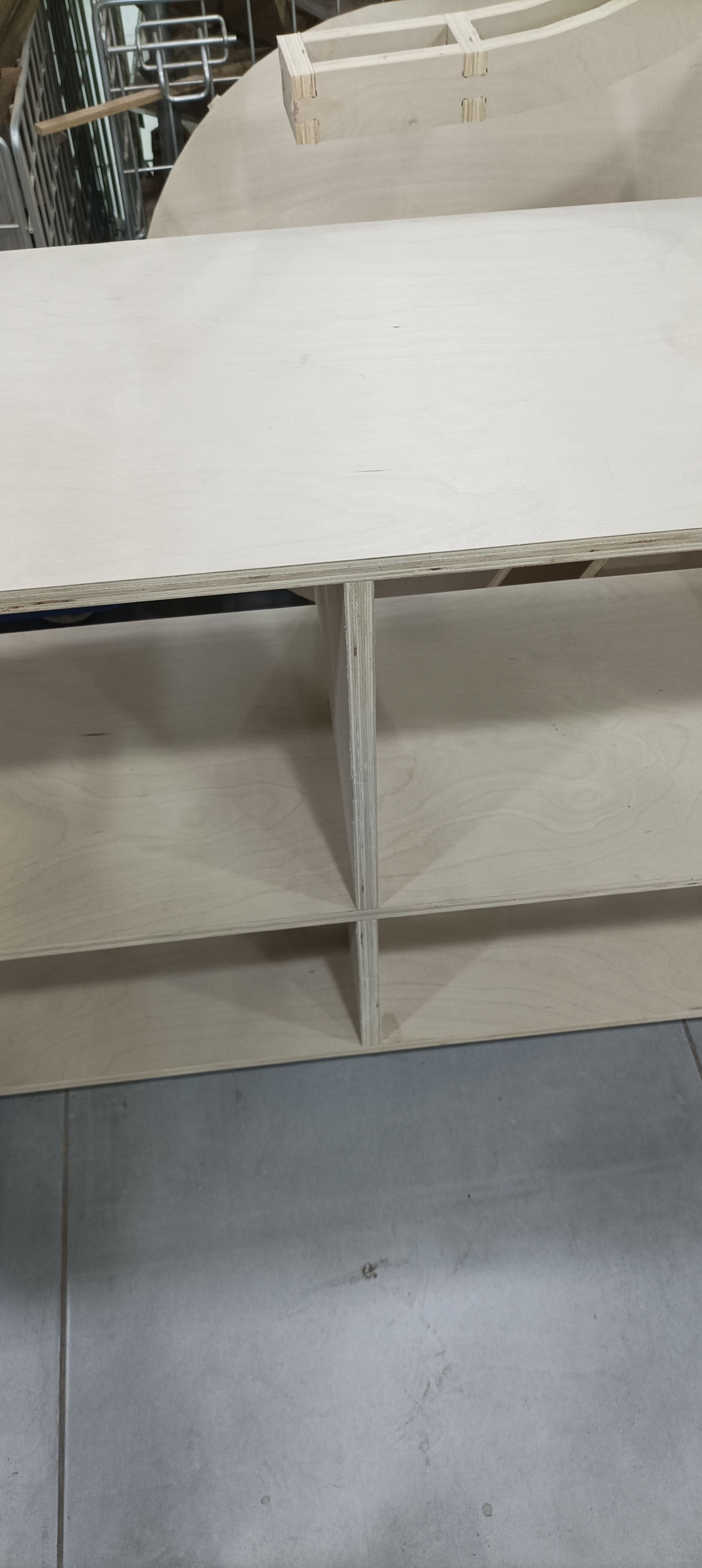
In celebration of Mother's Day this week, I've decided to create something truly special for my wonderful mother. I've chosen to craft a beautiful table where she can place her favorite snacks and treats, allowing her to indulge in the flavors she loves. It's my way of showing appreciation for all the love and care she has given me throughout the years.
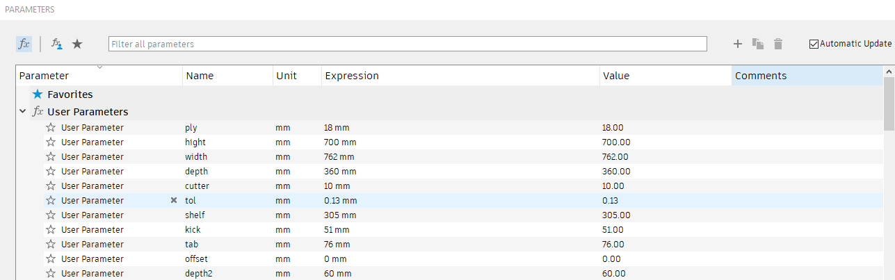
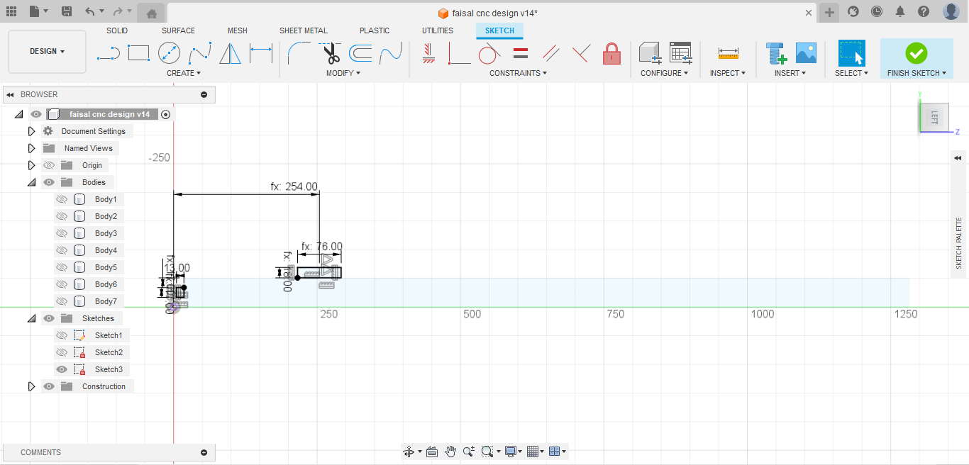
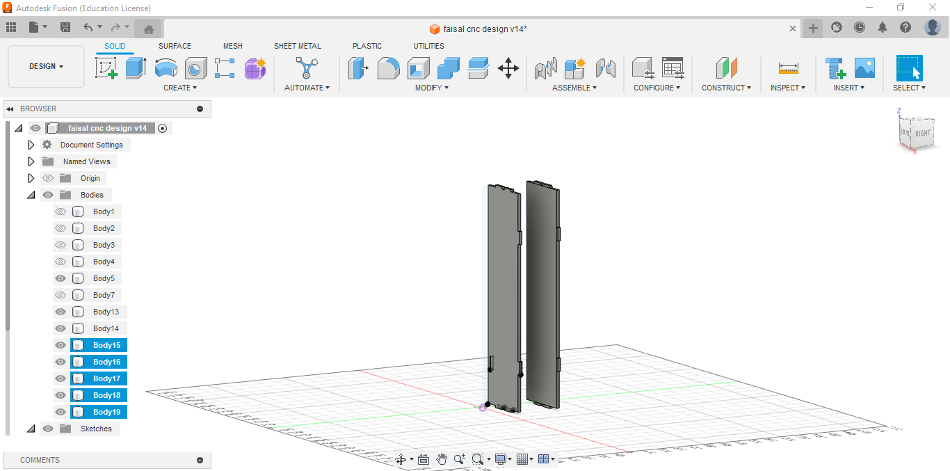
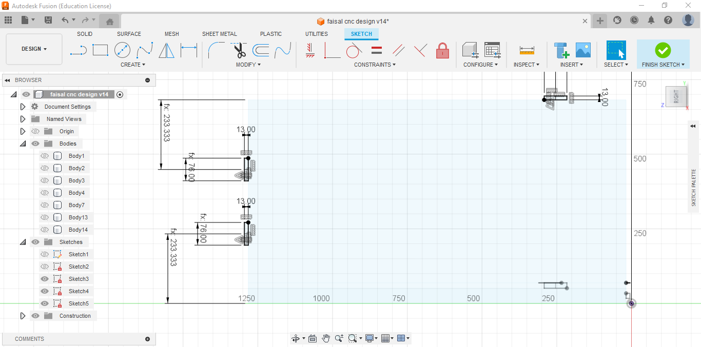
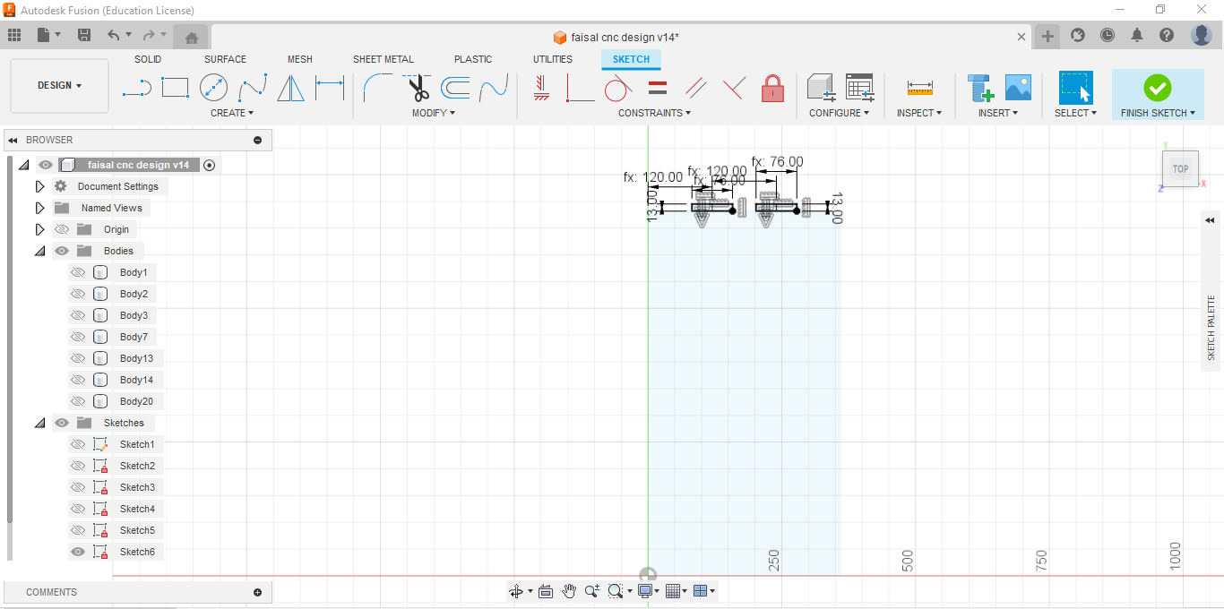
Here is my design and ofcourse I used parametric to fix any problem that may face me while designing
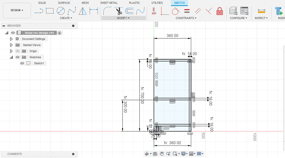
Here I started to draw my sketch.
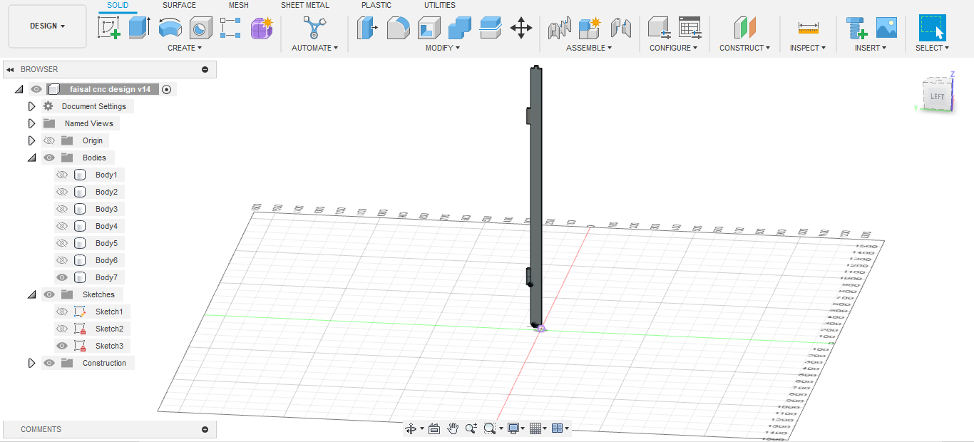
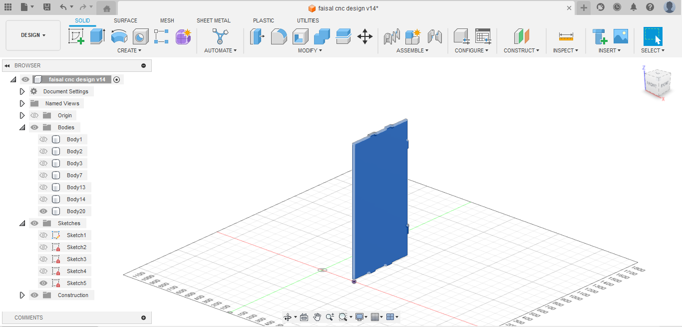
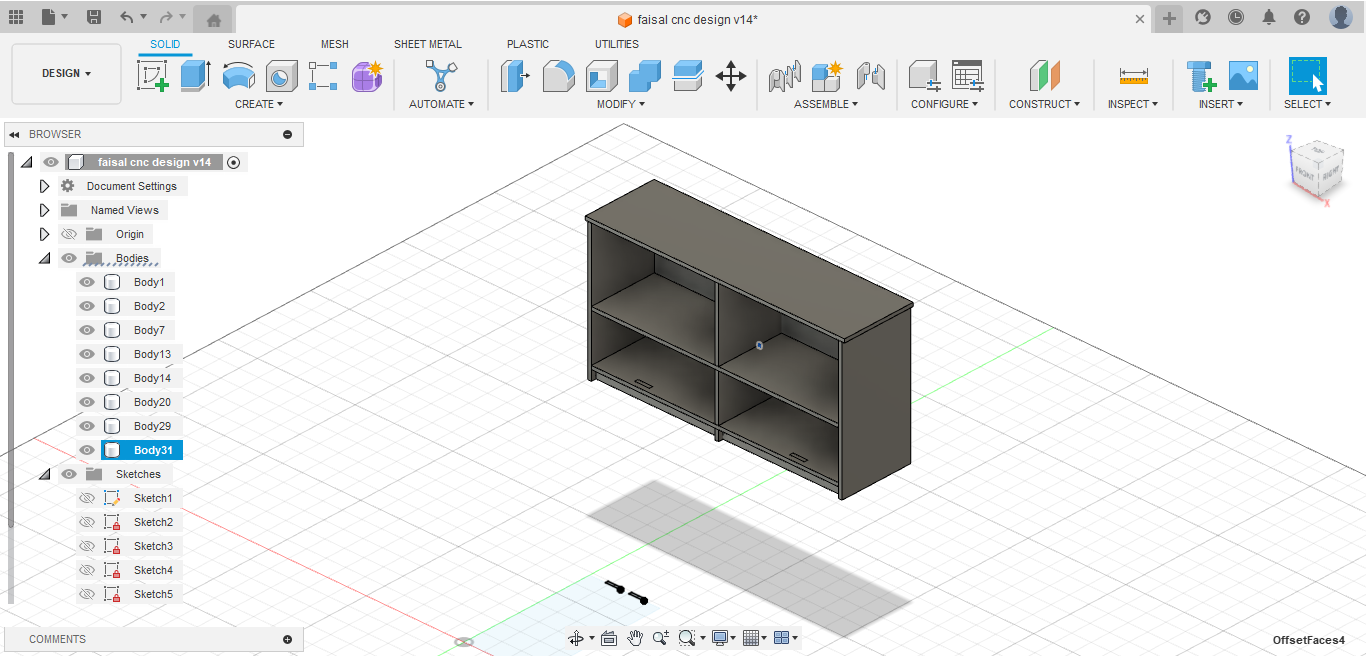
Then I extrude my design to the thickness of my board that I will cut it.
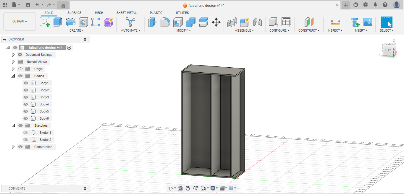
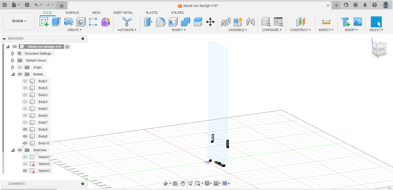
After that I put my design in the simulation to see if it will carry and hold the things that will put on and in it, it seems that there is a proplem so I solve it by putting a peice in the middle to strength the table.

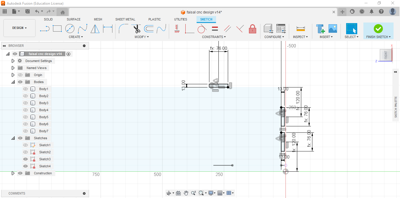
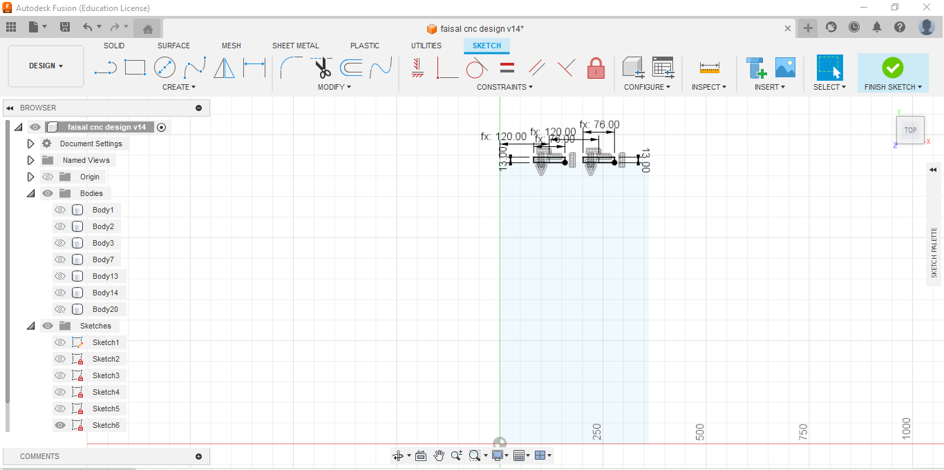
Here I continued adding the missing parts and the support part.
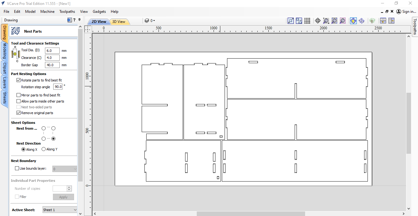
After finalizing the design for each project, I saved them individually as DXF files. Then, I imported all the DXF files into VCarve software for further editing and toolpath generation. This step allows for precise control over machining operations and ensures that each project is executed with accuracy and efficiency. By bringing all the projects into VCarve, I can efficiently manage and organize the machining process, optimizing toolpaths and settings to achieve the desired results for each project.
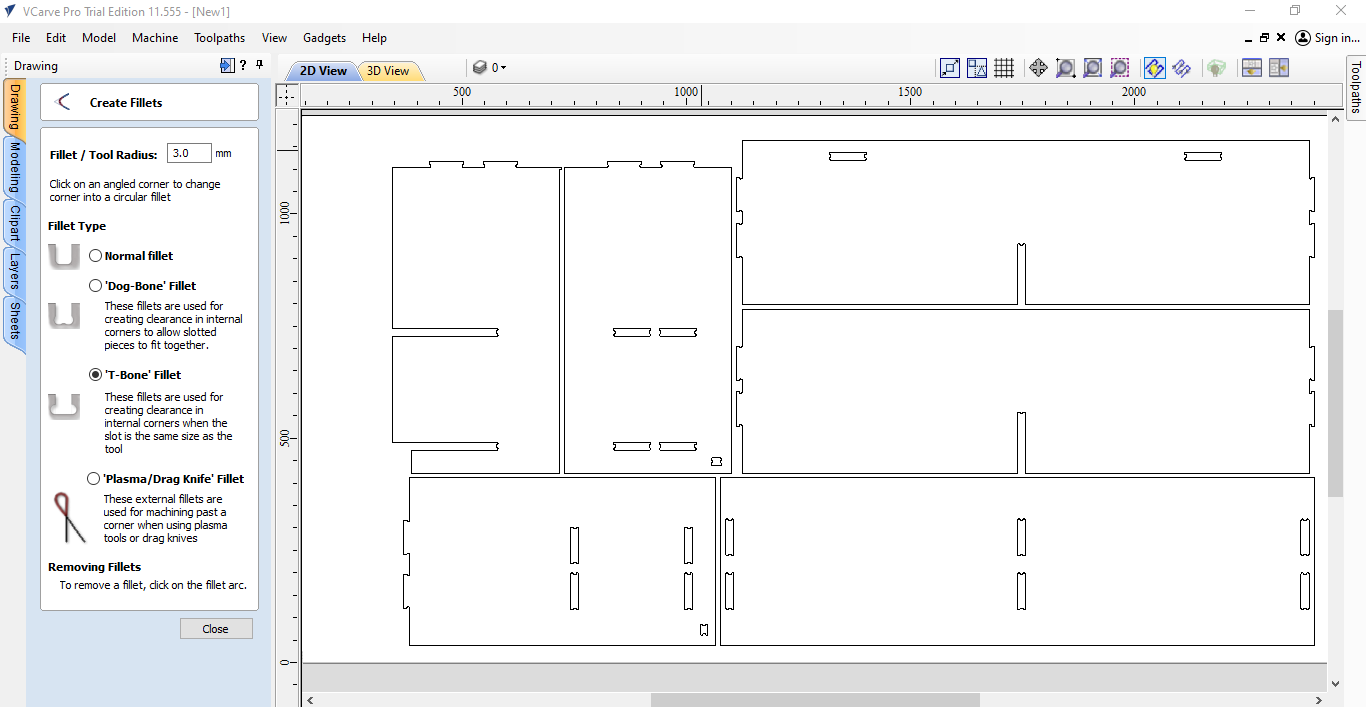
So here I put my dxf files and choose nest parts to distribute my designs in the area of the machine bed and taking the size if the board to see how my designs well fit in it.
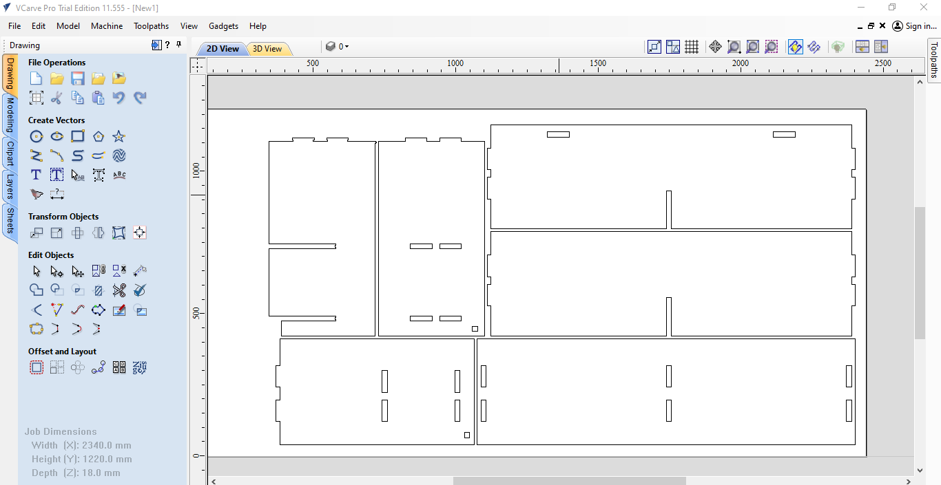
Here I used the T-bone fillets to insure the fingers will assemble togather.
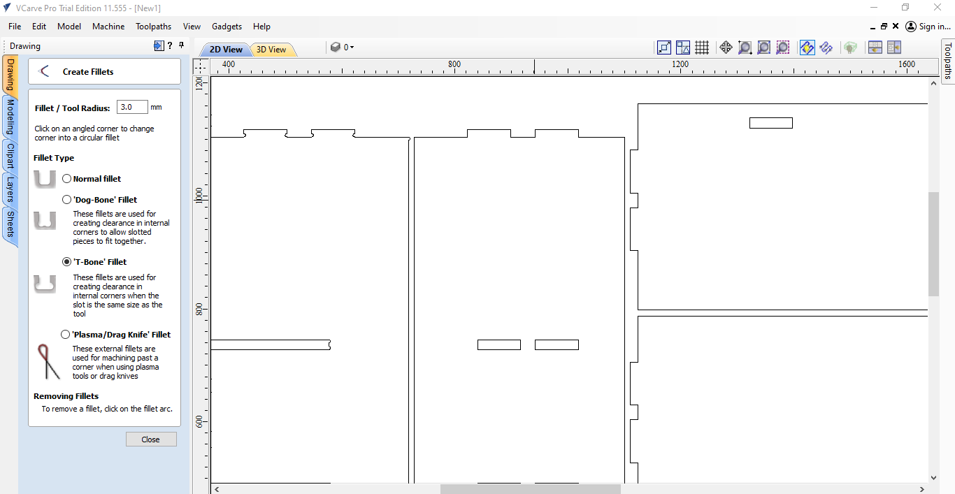
I chose the 3mm radius for the fillet.
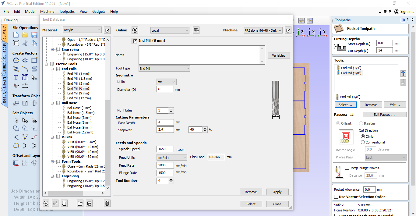
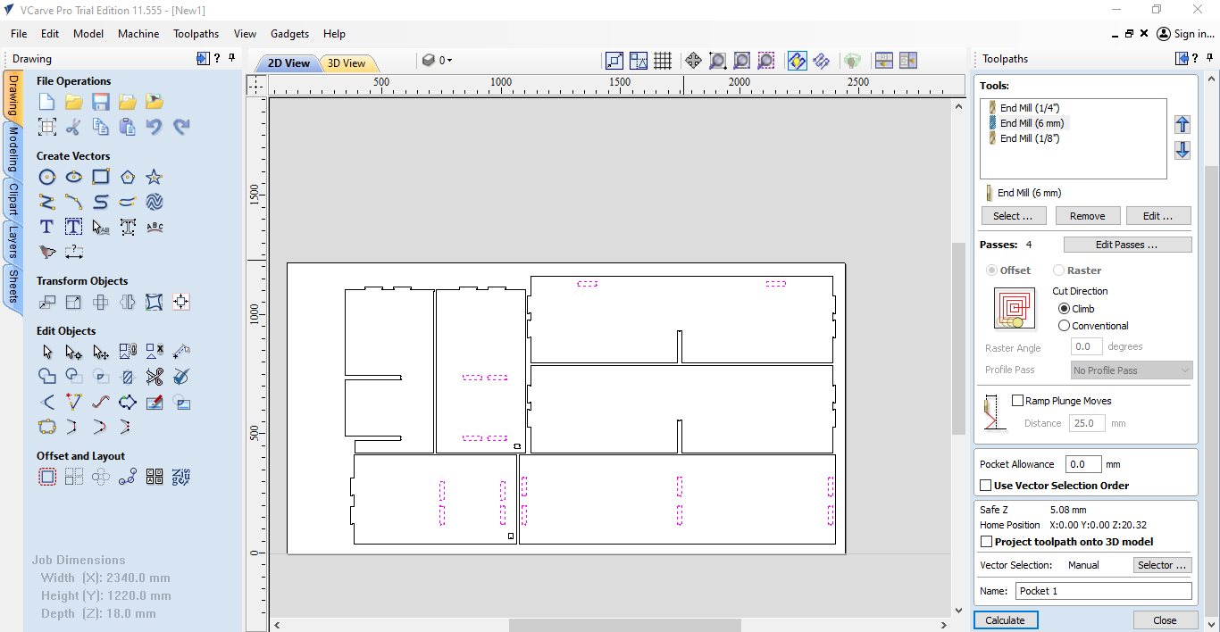
Here I chose the tool that I want to use and consider all the parameters and settings.
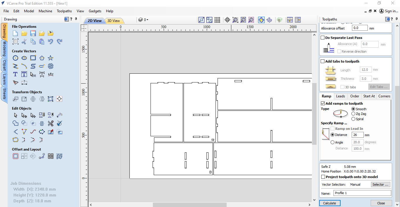
Here I chose the area that have to be cut depending on the previous settings.
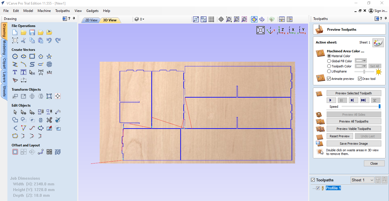
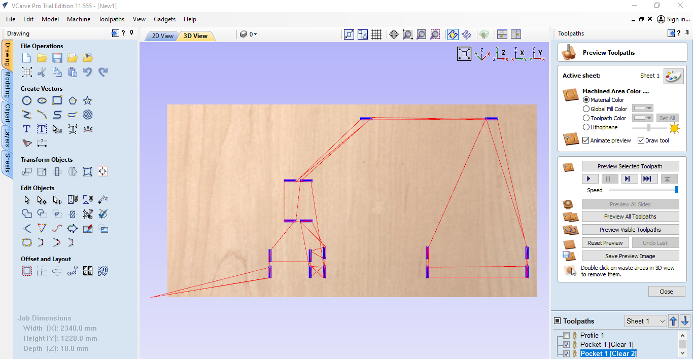
Here is the simulation.
Here I make the settings for the pockets.
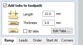
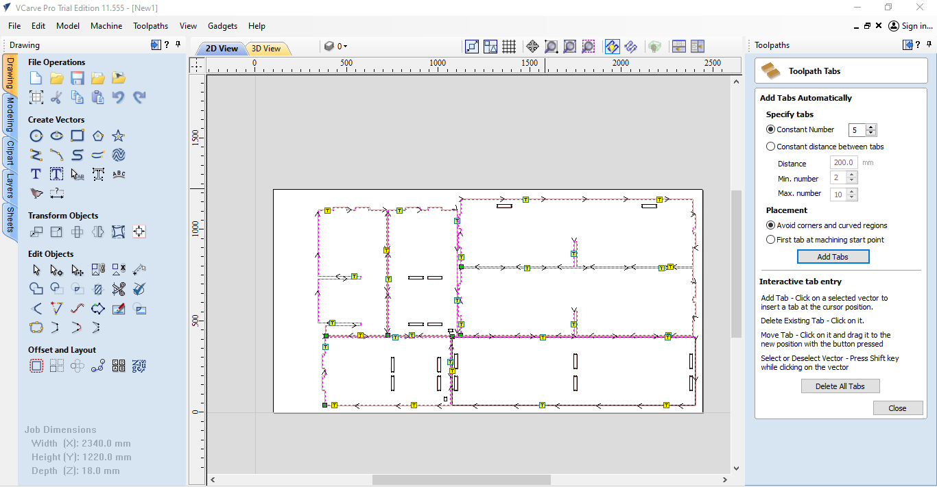
Ofcourse here I must put the tabs to insure the pieces that have been cut will not move to secure the tool from damage.
Here I selected the pockets and saw the simulation , ofcourse I will start with pockets because it easier to start than cutting the edges of the pieces.
Once I've ensured that everything is in order and all necessary preparations are complete, it's time to set up our machine for work. Here's how to proceed:
Machine Inspection: Start by inspecting the CNC machine to ensure that it's in good working condition. Check for any signs of damage or wear and tear that may affect its performance.
Material Setup: Prepare the material that will be used for the project. Ensure that it's the correct size and thickness for the intended design.
Fixturing: Securely attach the material to the machine bed using appropriate fixturing methods. This may involve screws, clamps, or other holding devices to ensure stability during machining.
Tool Selection: Choose the appropriate cutting tool for the job based on the material and design requirements. Install the tool securely in the machine's spindle.
Toolpath Generation: Use the appropriate software to generate toolpaths for the desired design. This involves specifying cutting depths, speeds, and feeds for optimal machining.
Zeroing the Axis: Zero the machine's X, Y, and Z axes to ensure accurate positioning of the tool relative to the material surface. This step is crucial for precise machining.
Test Run: Before starting the full machining process, perform a test run to ensure that everything is set up correctly. This allows for any adjustments to be made before proceeding with the final cut.
Safety Checks: Double-check all safety measures, including wearing appropriate protective gear and ensuring emergency stop buttons are easily accessible.
Start Machining: Once everything is verified and safety measures are in place, start the machining process according to the generated toolpaths.
By following these steps, we can ensure that our CNC machine is properly set up and ready to produce high-quality work.
Here I started to put the board on the CNC bed and start to attach the board to the bed by teh screws.
Here is the switch off and on of the machine.
This the position of the cnc and here I started to zero all the axis.
By this arrows I can move the machine in the axis that I want
Hrer I started to zero the x-axis and the rest of the axis
Here I chose the pocket file to start the operation.
Here the file make a simulation before starting the job
Her is the g-code from shopbot to make the machine do the job
Here there is the start button to make the machine start but we have to wait a while to warm up the machine.
Once the machine warmed up press the green button
Then lets the fun begin
Here is the machine doing the first job which is the bocket of my desk
Then here starting to cut the edges
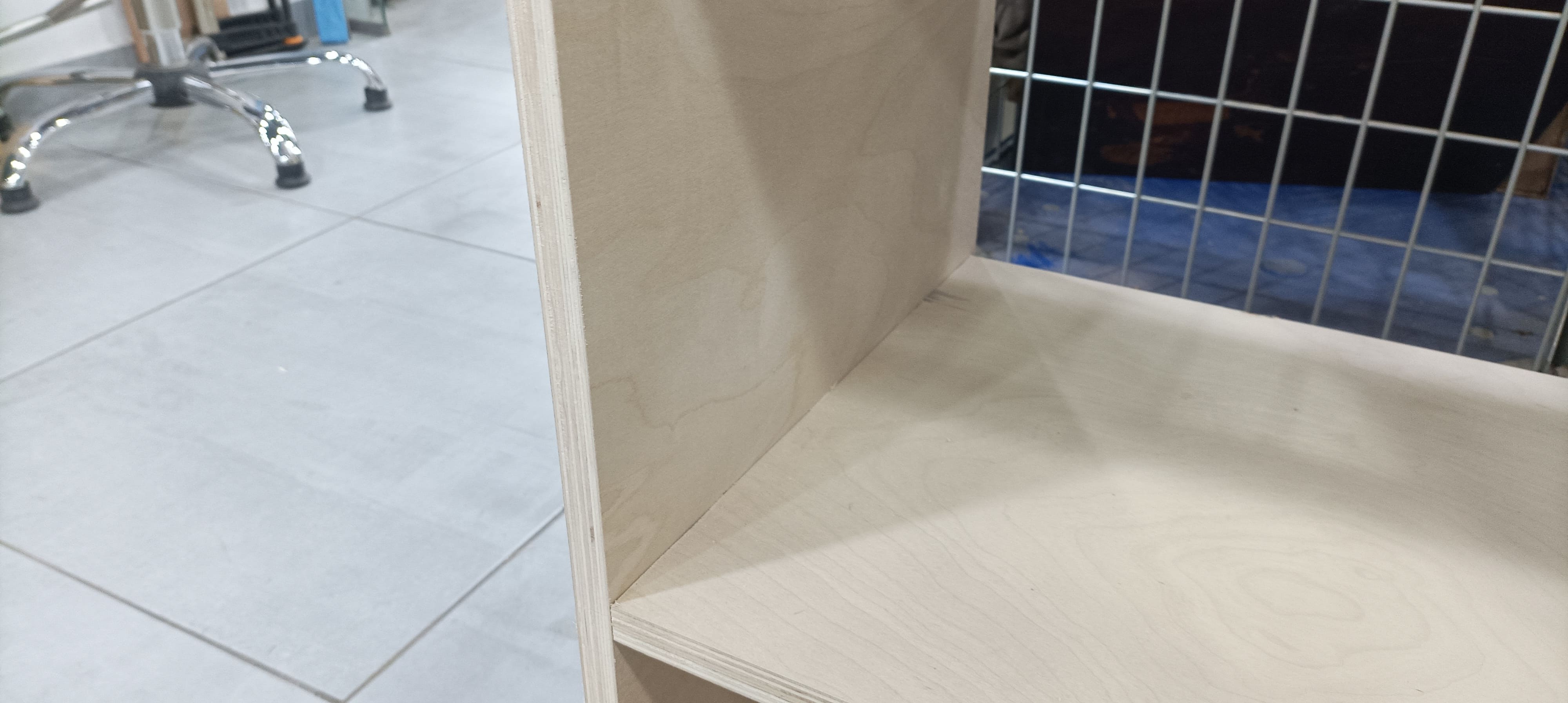
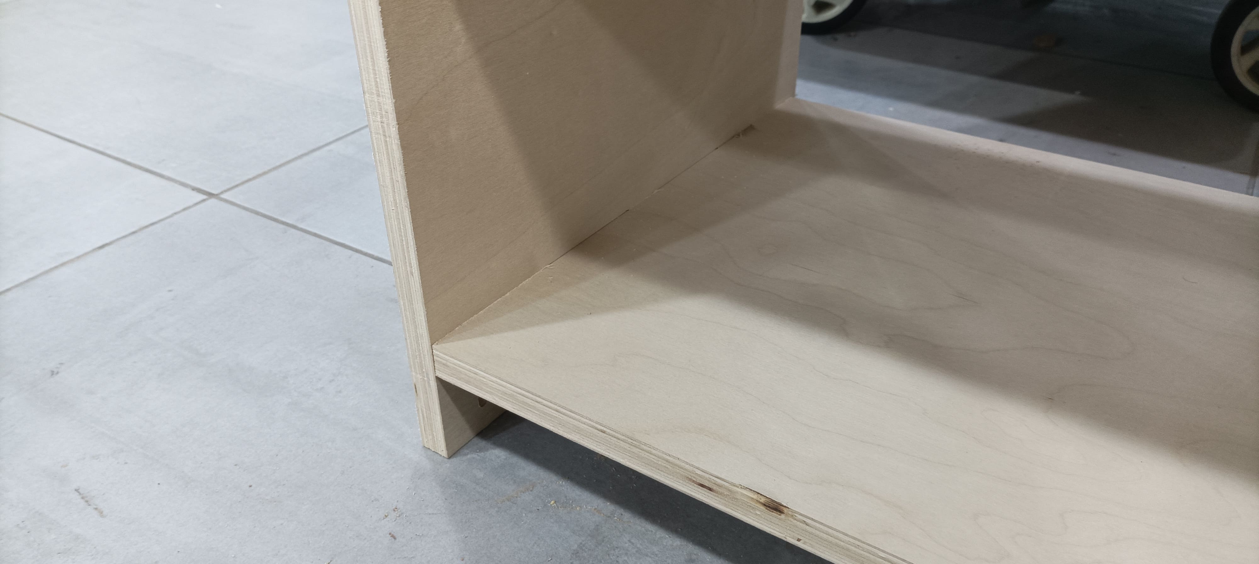
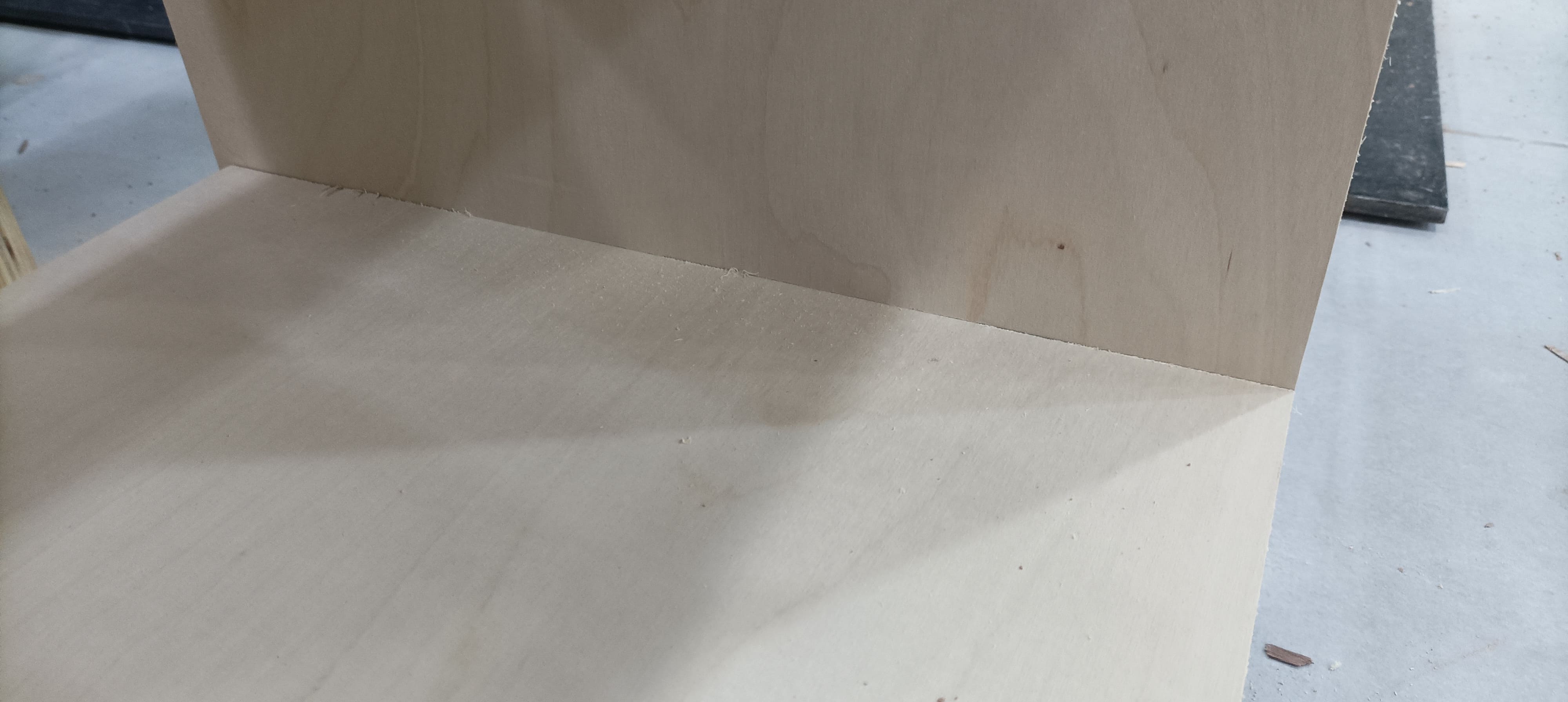
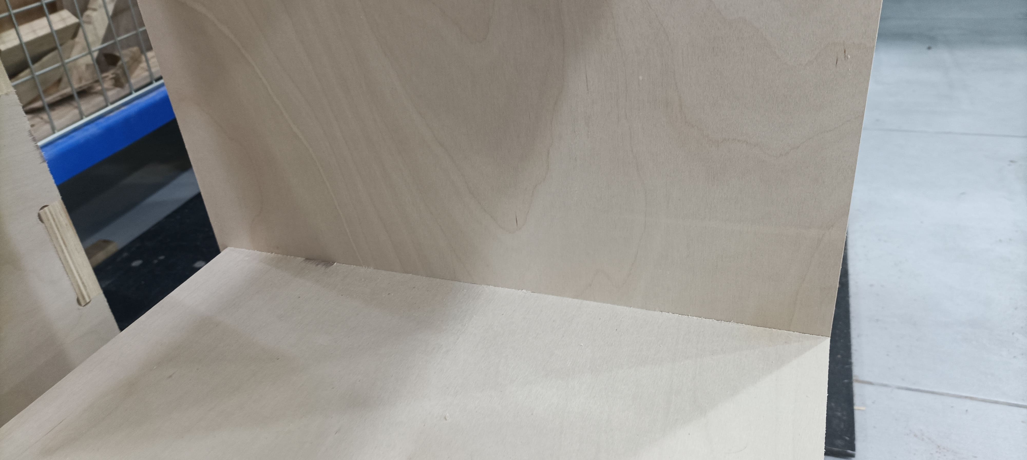
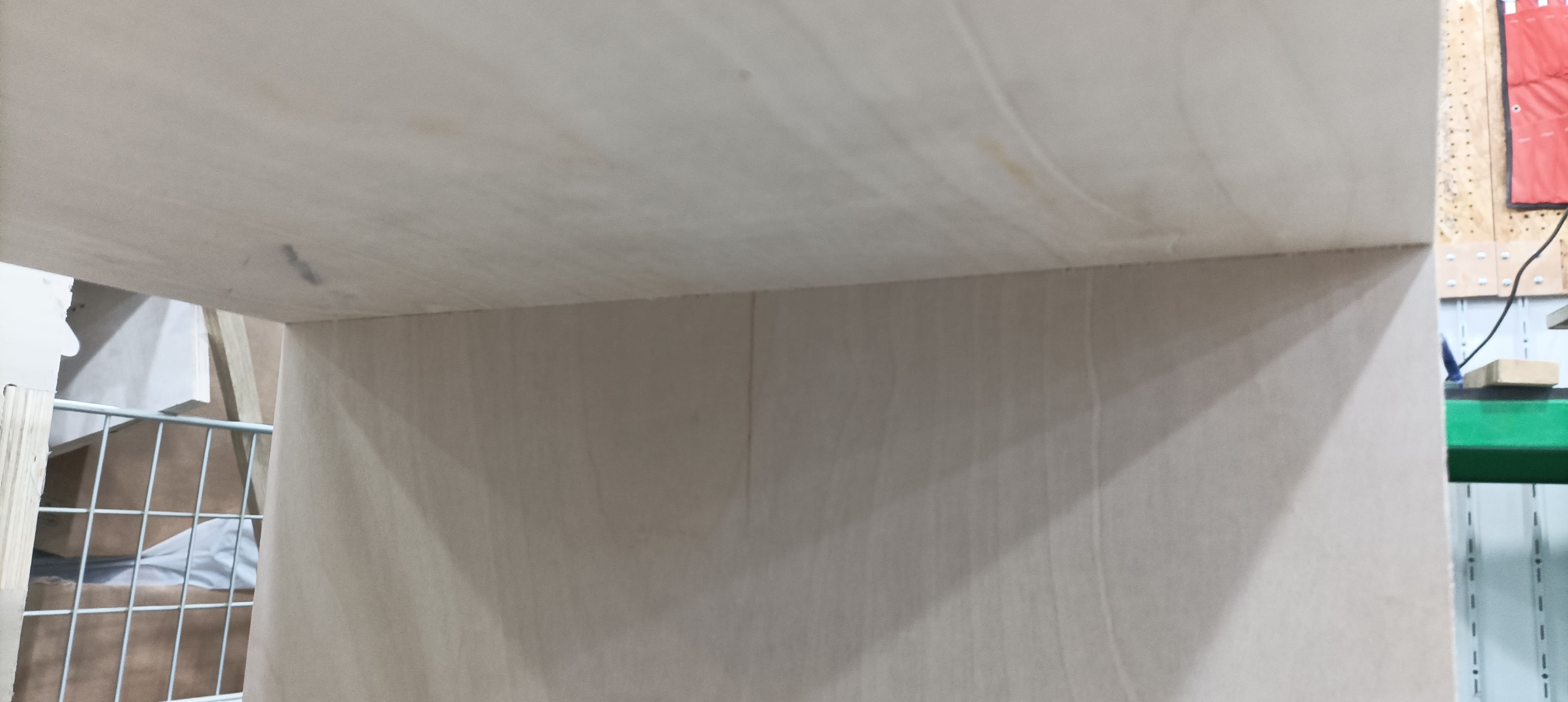
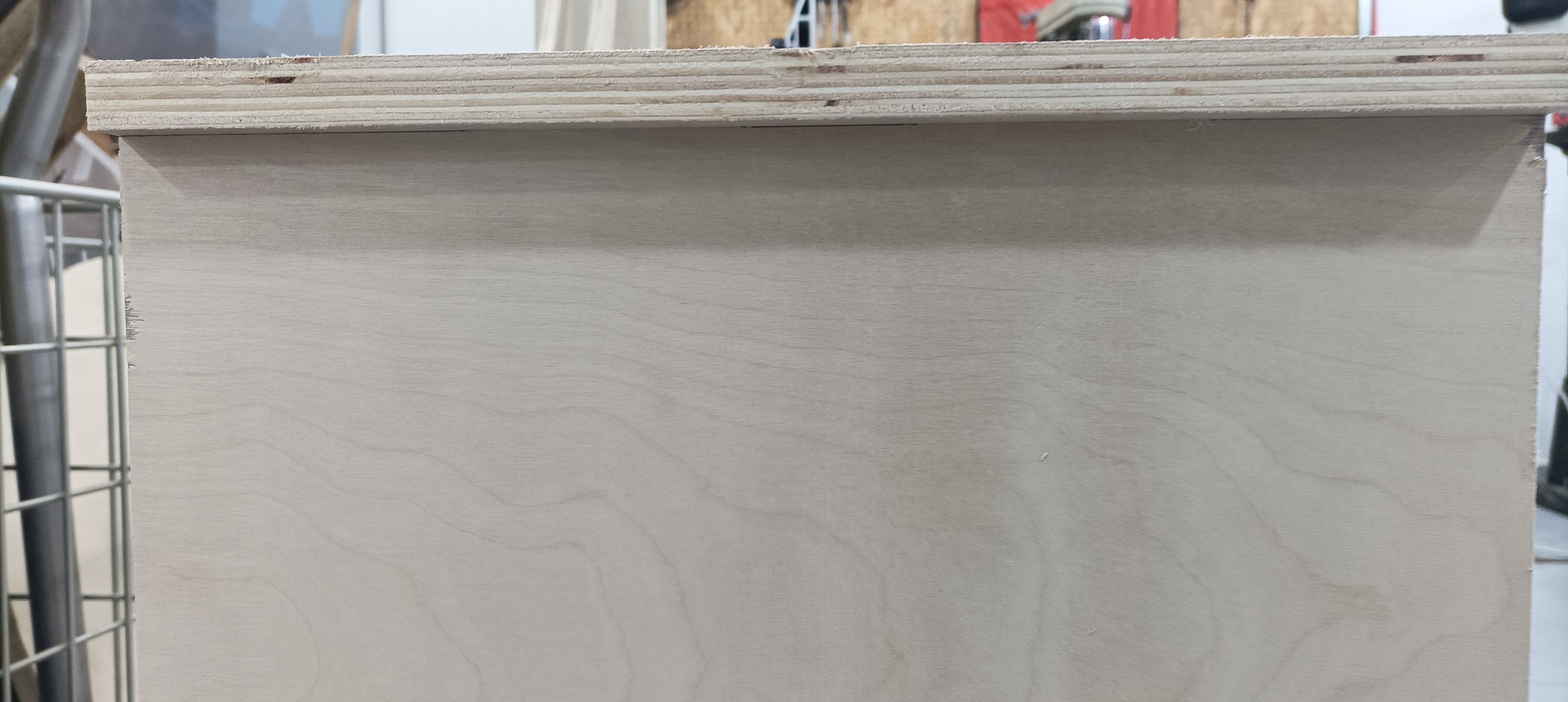
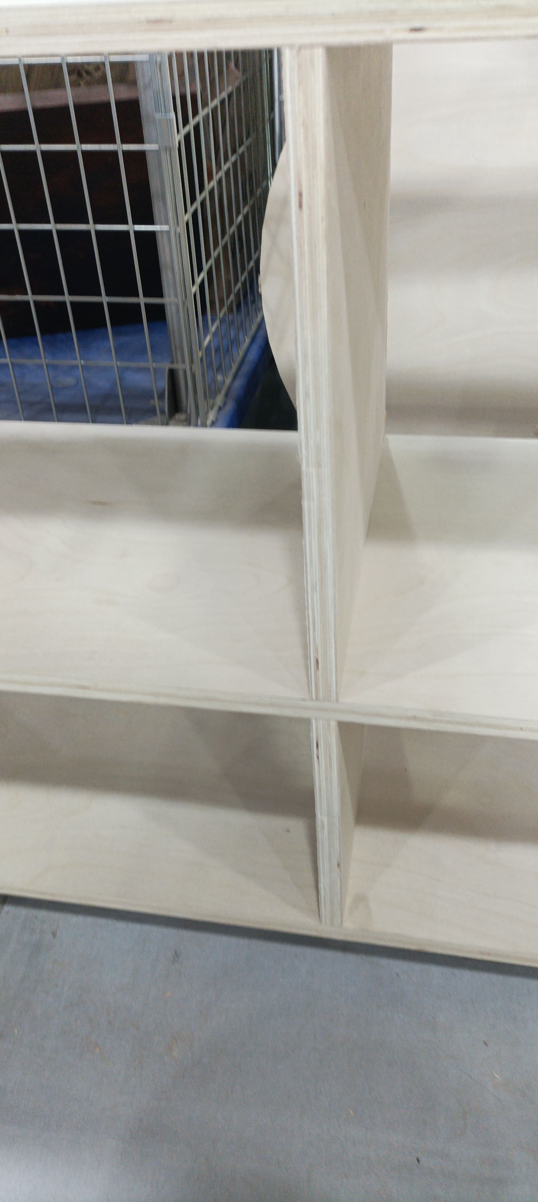
Her I started to assemble the parts together and fit the parts in the suitable place