Computer-Controlled Cutting
The group assignment focused on characterizing various aspects of the Trotec Speedy 400 laser cutting machine. Here's a summary of the findings:
Focus: The optimal focus distance for the laser cutter was determined to be 25mm, ensuring optimal performance and precision during cutting and engraving processes.
Power and Speed: A meticulous exploration of power and speed settings was conducted using a 4x4 grid of squares, each representing a unique combination. The optimal settings for MDF material of 3.3mm thickness were found to be 100% power with a speed of 0.3m/s.
Rate: The laser pulse rate was set at 1000 Hz for the material used.
Kerf and Joint Clearance: The cutting kerf, representing the amount of material removed during the cutting process, was determined to be 0.1mm. This was found through testing comb-like structures with varying slot thicknesses, with the optimal fit observed at slots with a thickness of 3.1mm.
By thoroughly understanding these characteristics and optimizing settings accordingly, precise and accurate cuts can be achieved, crucial for high-quality results in laser cutting projects.
Individual assignment:
The individual assignment involved creating a parametric modular kit for laser cutting using Fusion 360. The process was documented step by step:
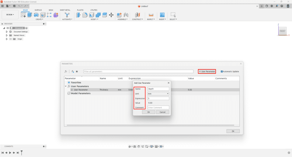
Designing the Parametric Shapes: Using Fusion 360, parametric shapes were designed for the modular kit. Parameters were added to facilitate easy adjustments during sketching.
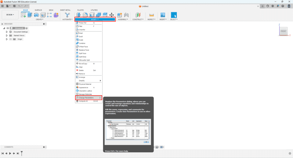
Changing Parameters in Fusion 360:
- Opened the Parameters dialog box by navigating to the "Modify" option in the toolbar and selecting "Change Parameters."
- Located the desired parameter in the list.
- Modified the parameter value by double-clicking on it, entering a new value, and pressing Enter.
- Verified the changes to ensure they were applied correctly.
Updating the Design: After making parameter changes, clicked "OK" to close the Parameters dialog box. Fusion 360 automatically updated the design to reflect the changes made to the parameters.
Benefits of Parametric Modeling: Changing parameters in Fusion 360 allows for easy exploration of design alternatives and facilitates parametric modeling. It enables iterative design changes without manually editing each feature, thereby streamlining the design process and promoting efficiency.
By documenting the process of creating parametric designs and adjusting parameters in Fusion 360, the individual assignment provided a comprehensive overview of utilizing parametric modeling for laser cutting projects.
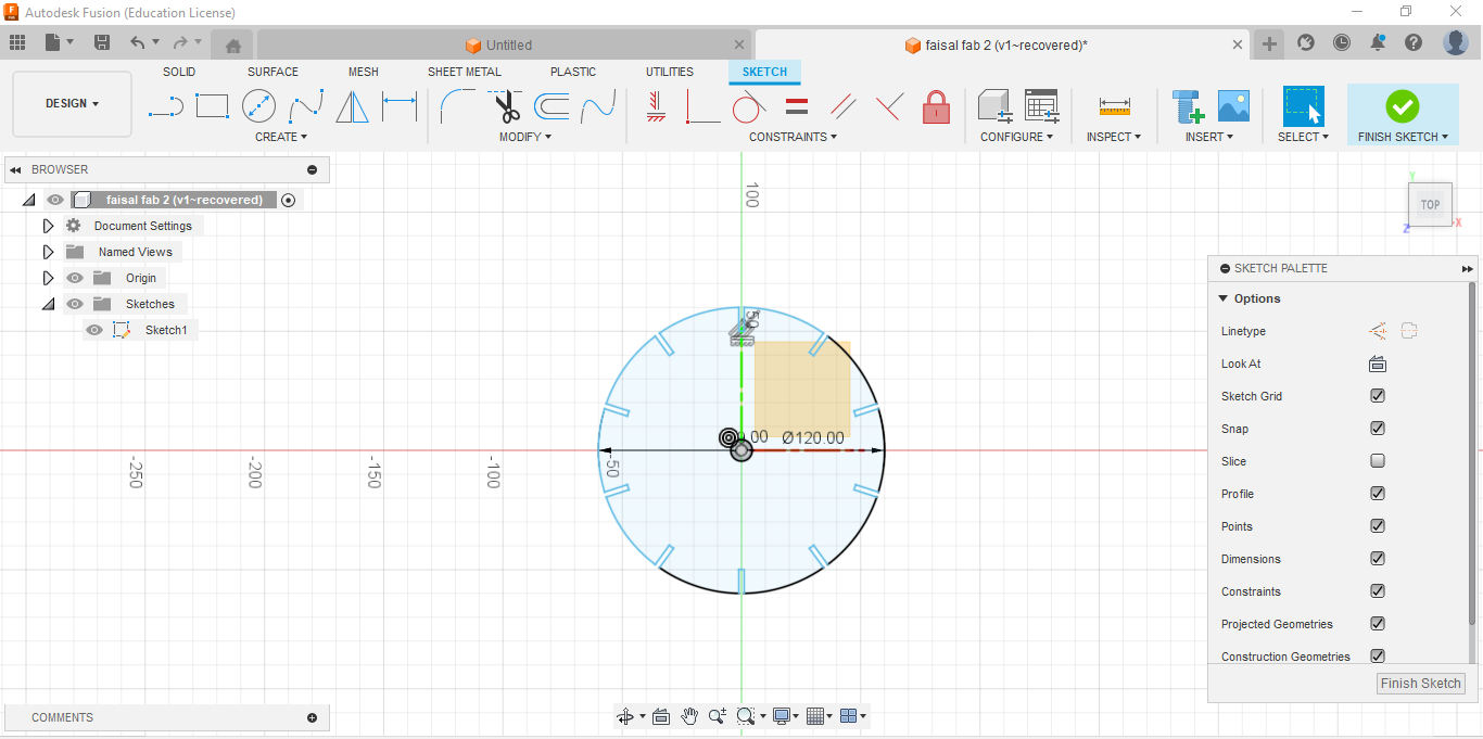
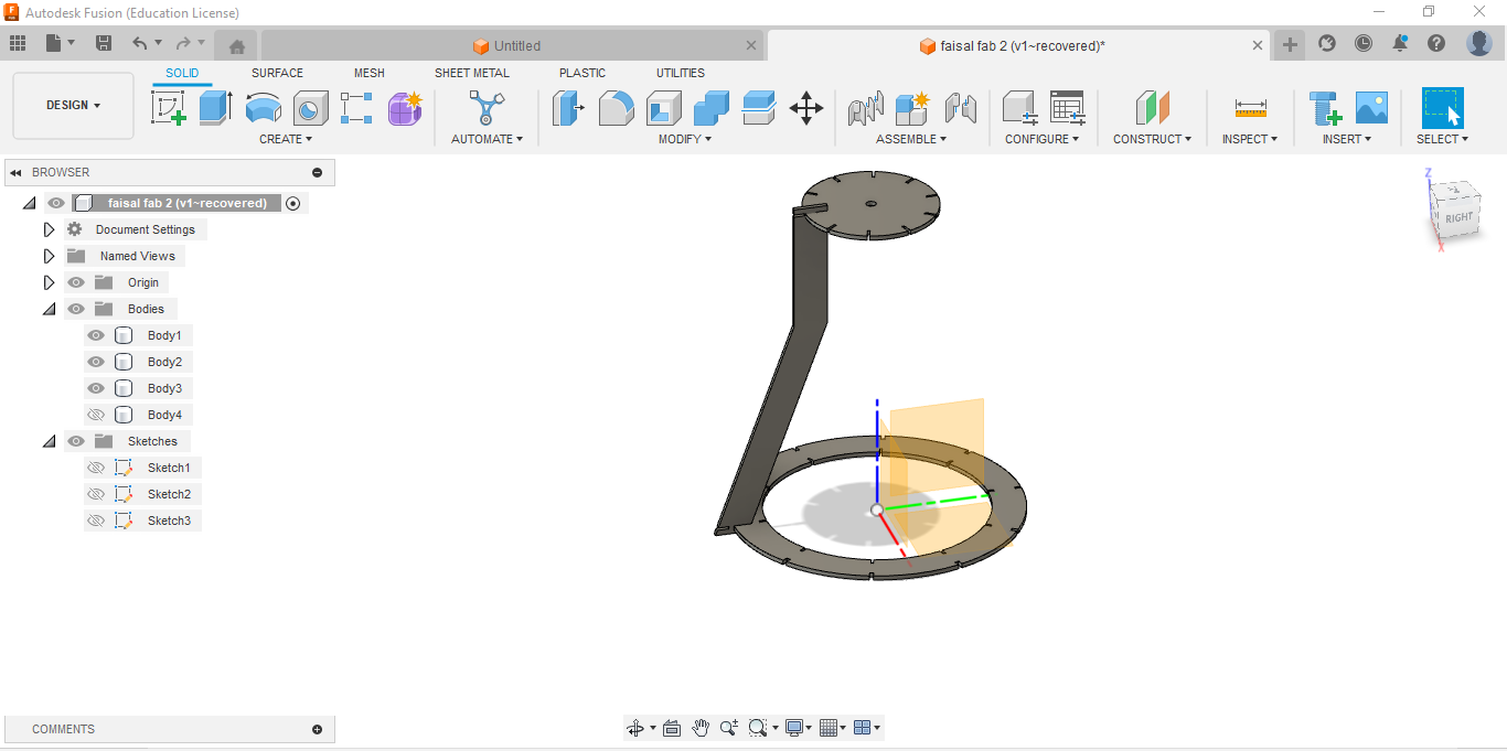
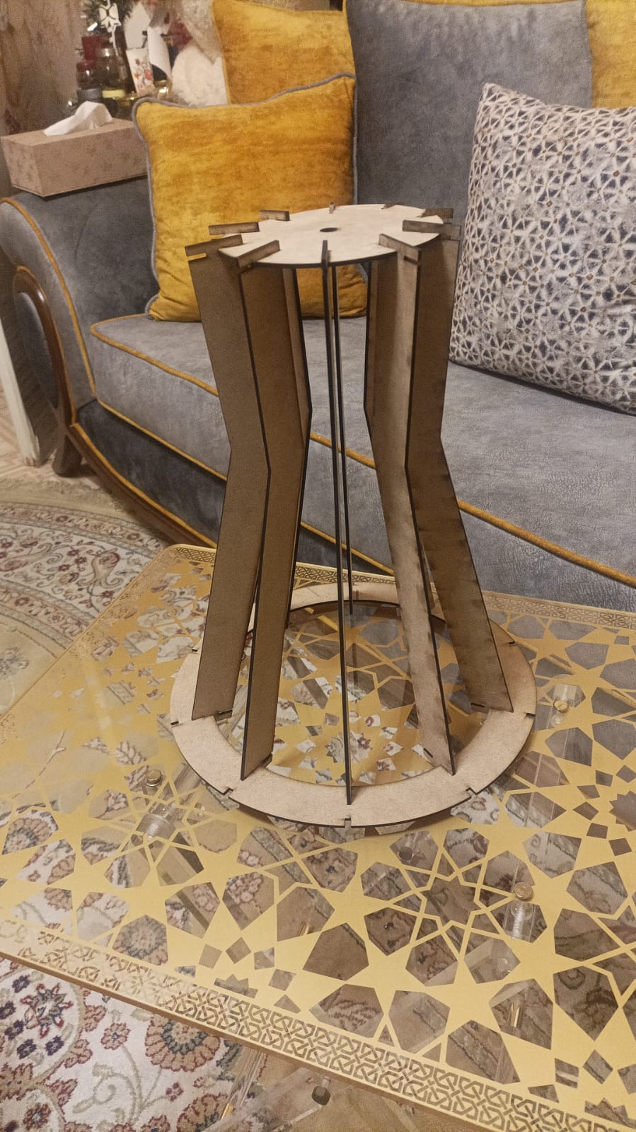
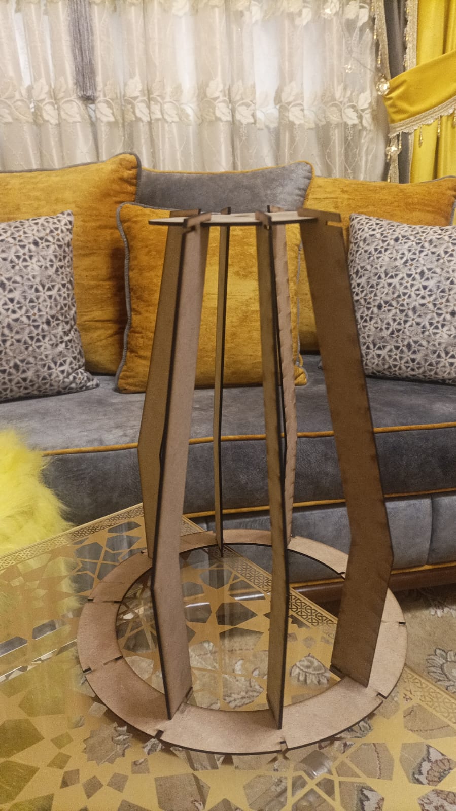
In this assignment I tried my own lampshade that can have more than shape.I started draw it in fusion 360 and assemble it.
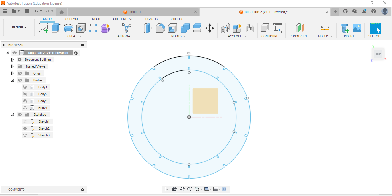
I started to design the top part of my design.
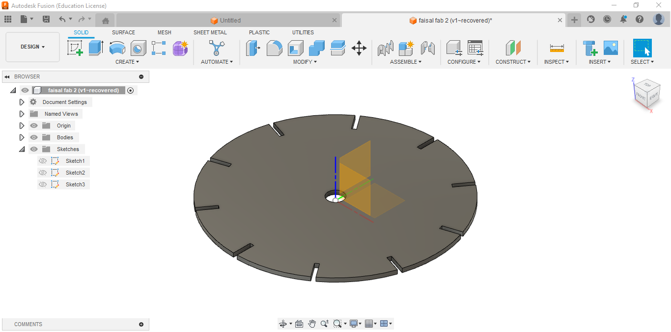
Here I extrude my design to the suitable thickness which is 2.25mm.
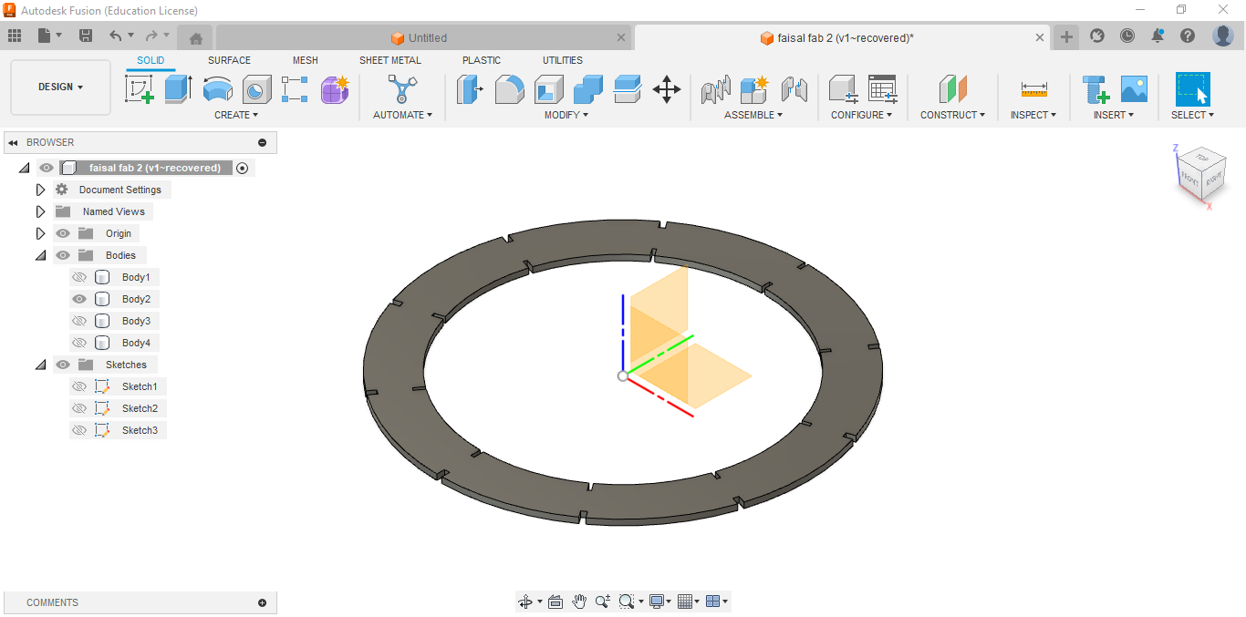
Here I started the bottom part.
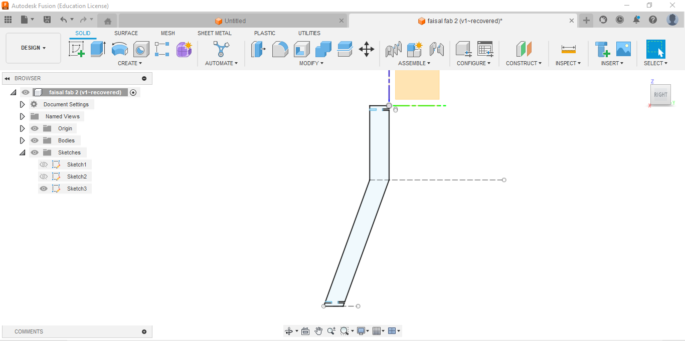
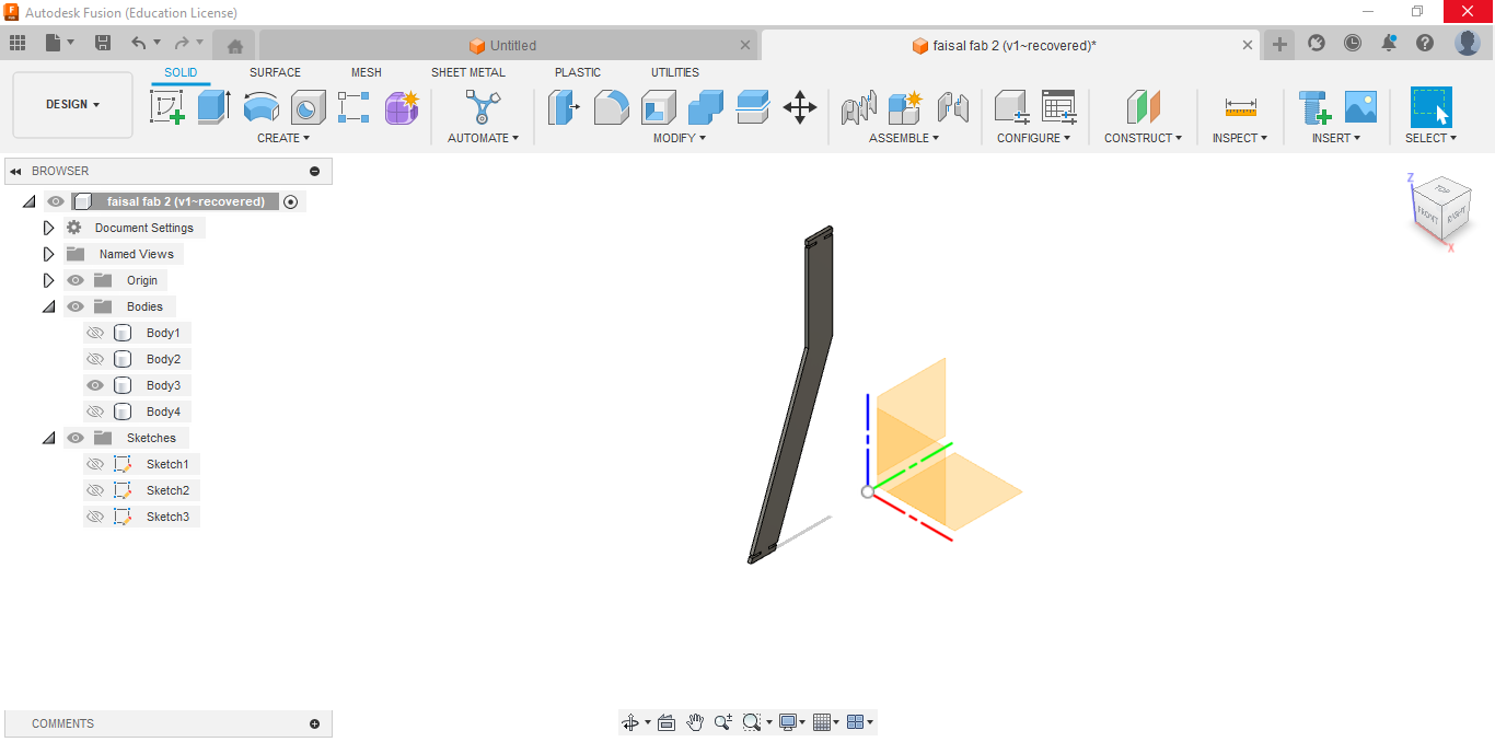
Here I drew the leg that will connect the top part with the bottom part.
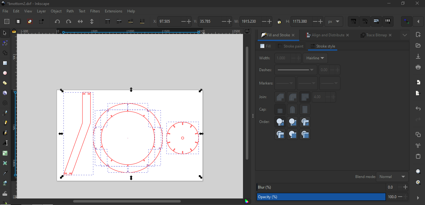
After completing the parametric designs in Fusion 360, I exported the sketches to DXF files. Then, I imported these DXF files into Inkscape software. In Inkscape, I adjusted the settings to prepare the designs for laser cutting. This included configuring parameters such as power, speed, and focus to ensure precise cutting according to the design specifications. By using Inkscape to set the appropriate cutting settings, I ensured that the laser cutter would accurately produce the desired shapes from the parametric designs created in Fusion 360.
Then I started to cut them
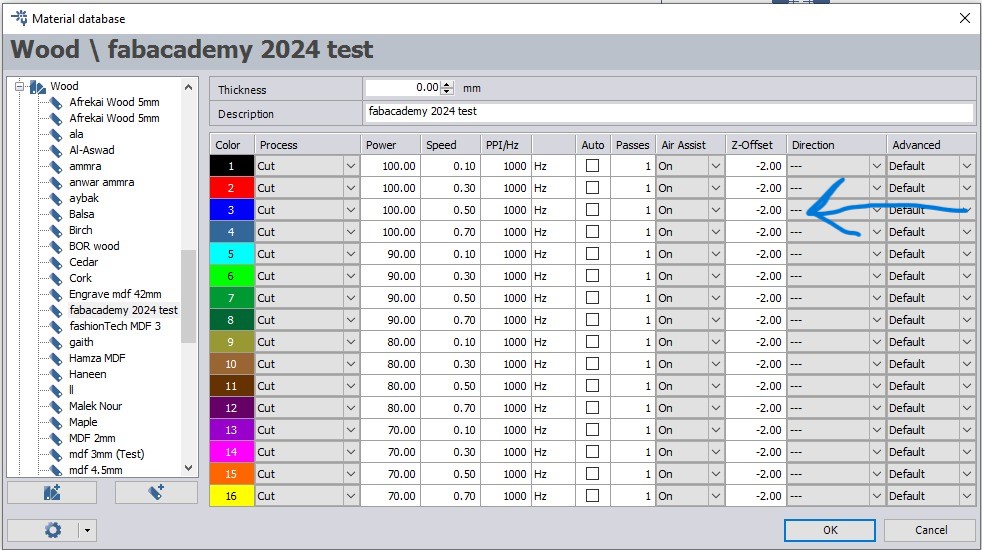
I used this setting because I felt it was the best setting for my design
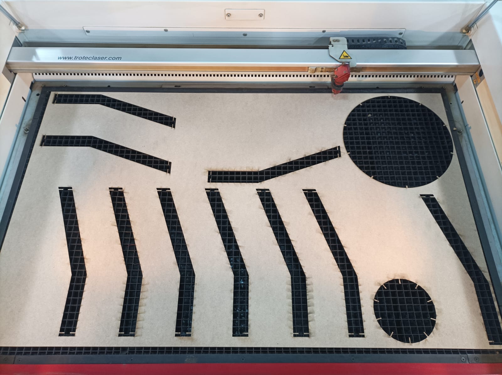
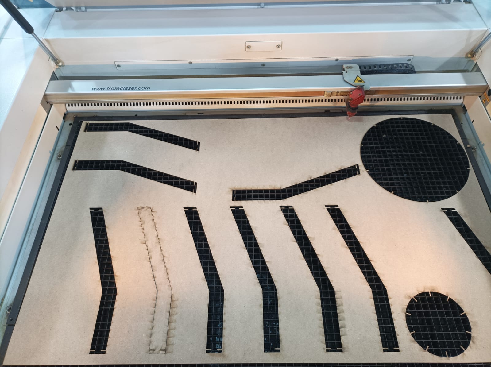
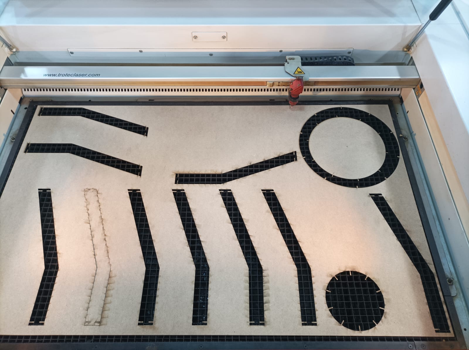
Unfortunately, while moving my designs, I made some errors that resulted in them occupying more space than originally intended.
And her the final product:

Vinyl Cutter
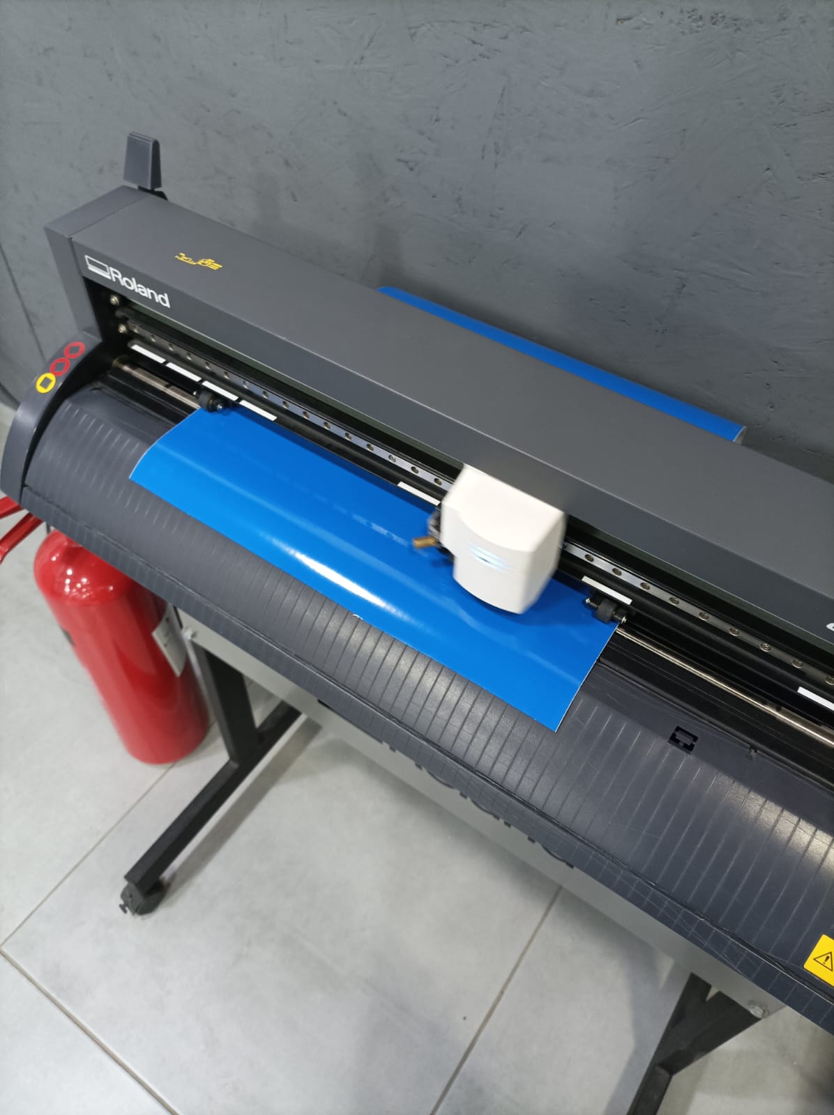
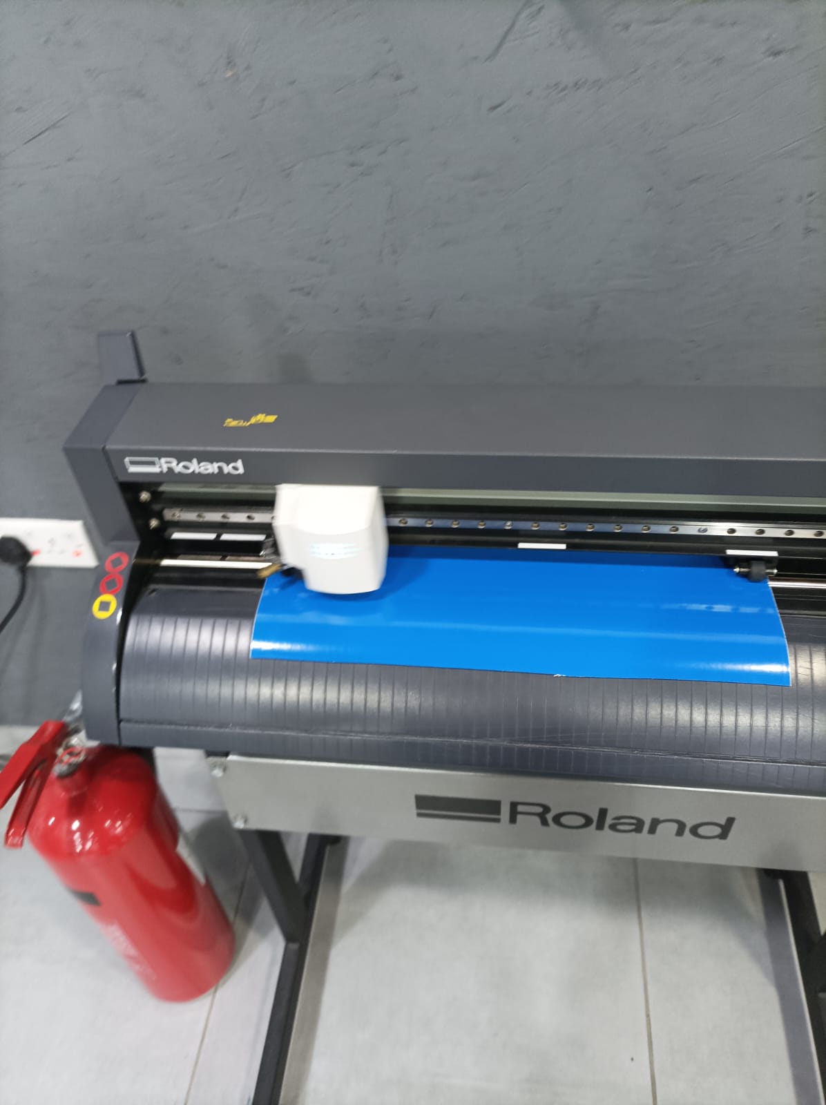
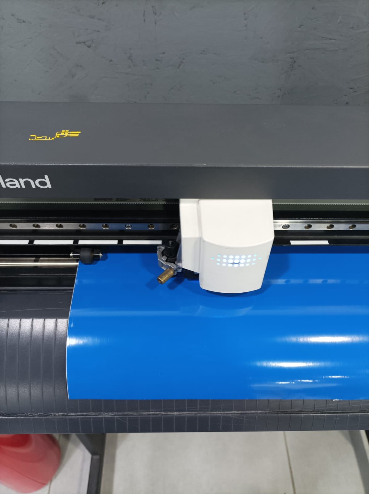
There are different types of vinyl cutters. In TechWorks we have Roland CAMM-1 GS-24:
Using a 45-degree blade for a vinyl cutter is ideal for a variety of materials, offering a balance between detail and thickness. Proper blade length is crucial; only the tip should protrude to cut vinyl without damaging the backing. Adjust the blade using calibration tools or test cuts to ensure clean cuts with minimal pressure, enhancing the quality and efficiency of your projects.
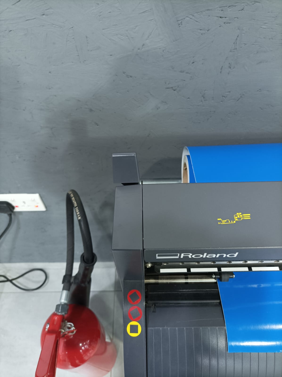
It's crucial to ensure that the rollers are positioned correctly beneath the white bars.
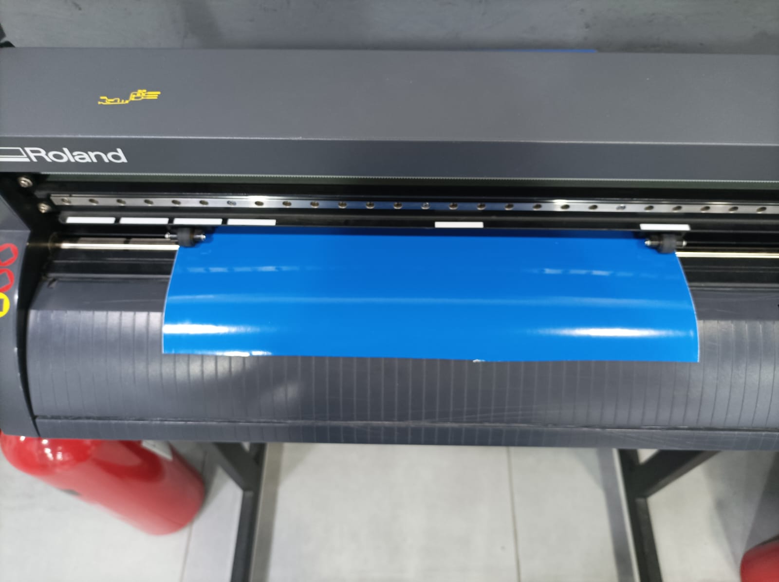 To attach the sticker roll, ensure that the handle lever is open. Then, insert the roll and close the lever securely.
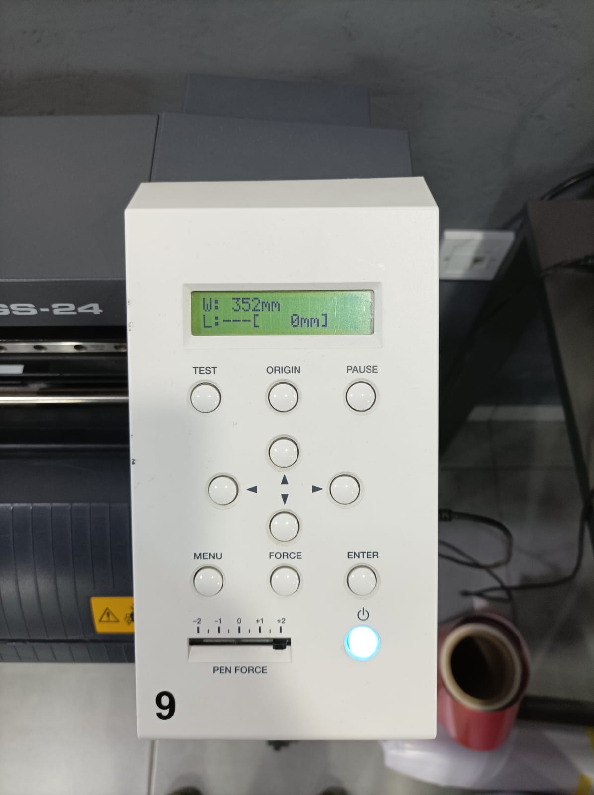
We control the machine via the control panel buttons, selecting our desired cutting mode: piece, edge, or roll. Typically, we opt for cutting individual pieces.
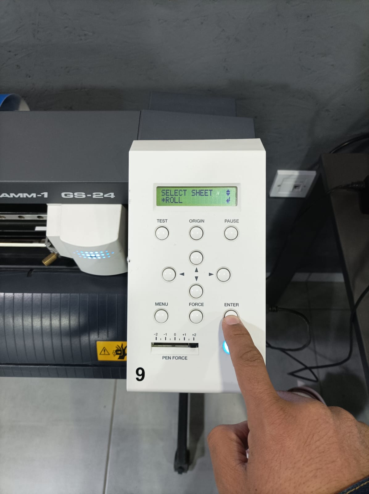
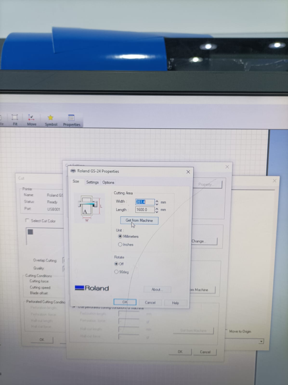
Once I press the enter botton it will make the head of the machine measure the width of the roll that I put it in the machine.
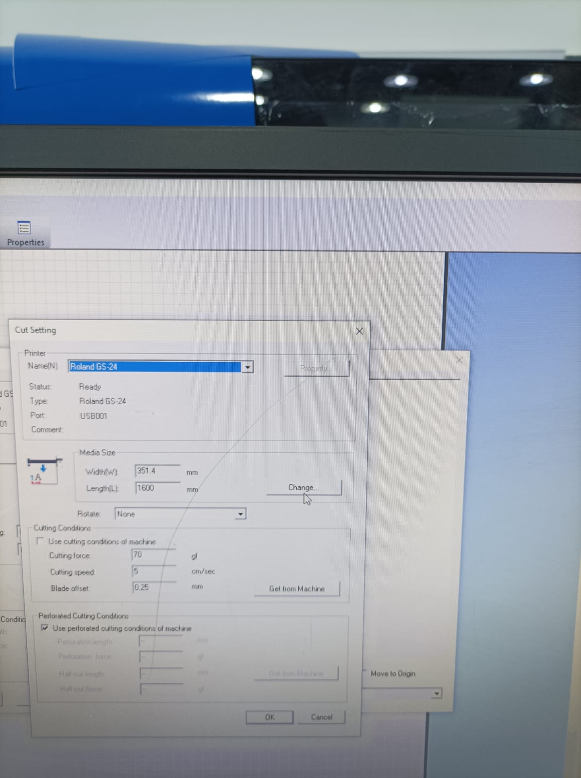
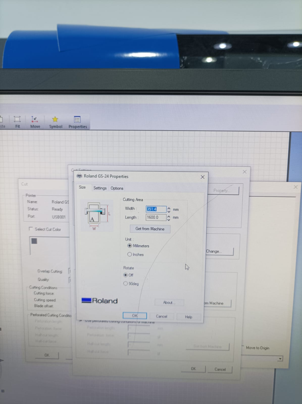
Here it seems the width of the roll is 352mm.
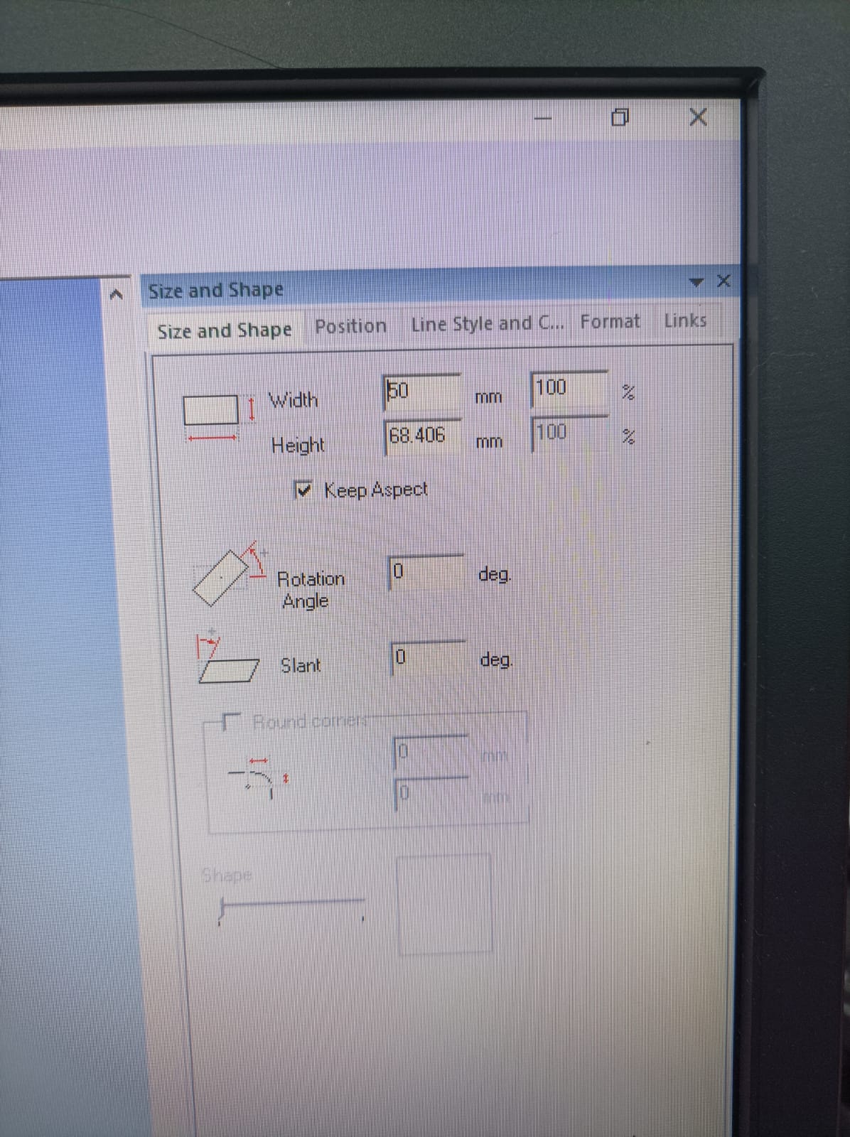
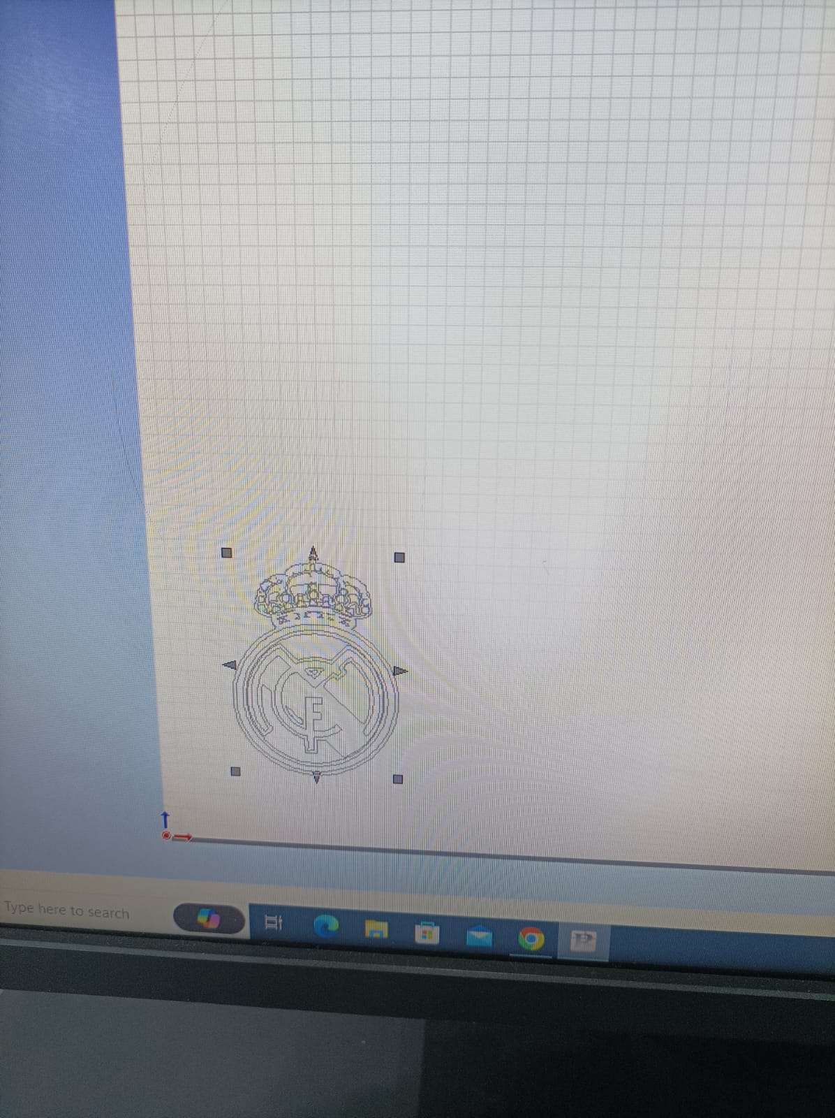
Because I am real madrid fan I tried to take the photo from google and adjest the suitable size to cut it

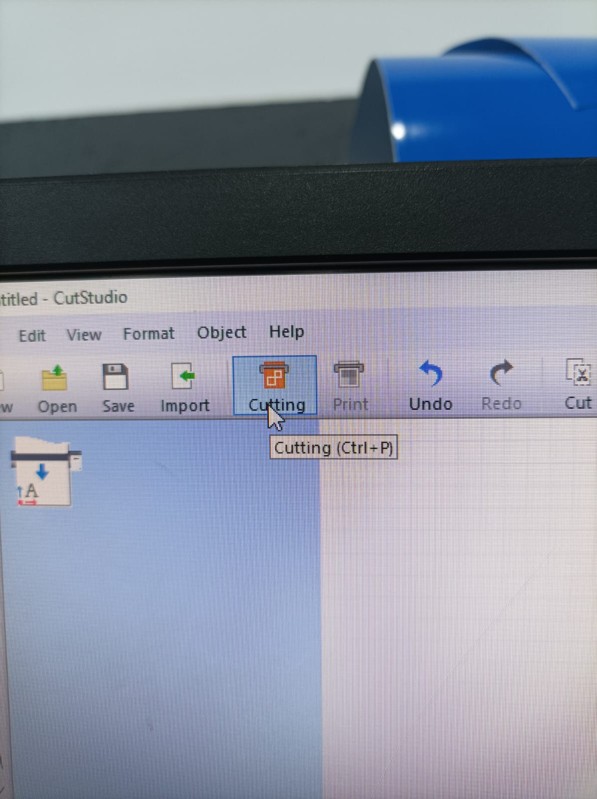
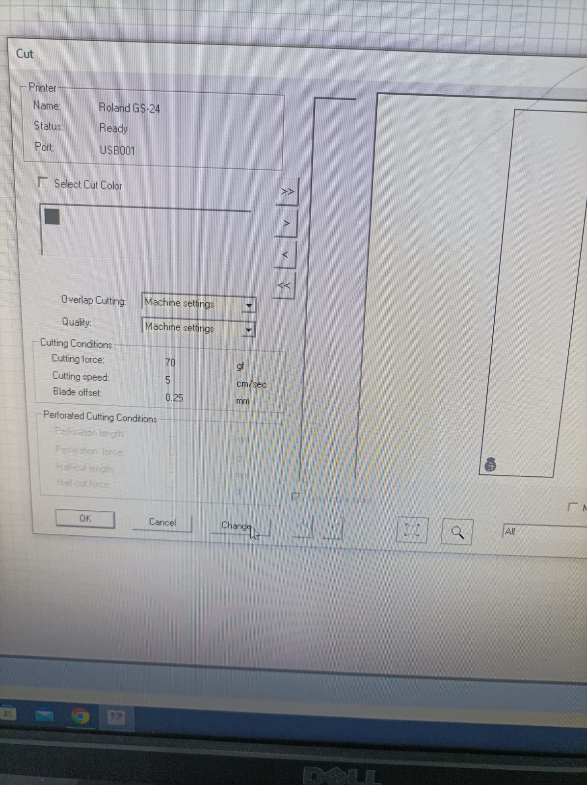
After clicking the cutting command, a window will open. From there, continue clicking "Change" until you reach the option to adjust the distance of the roll, ensuring it's set correctly for the machine.
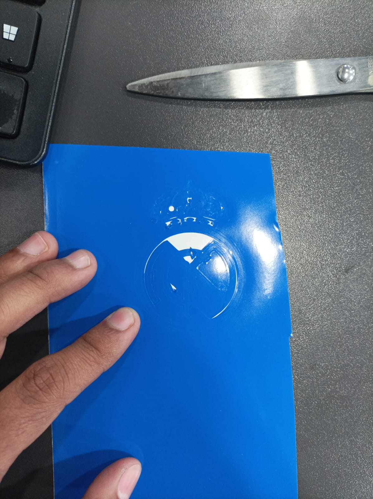
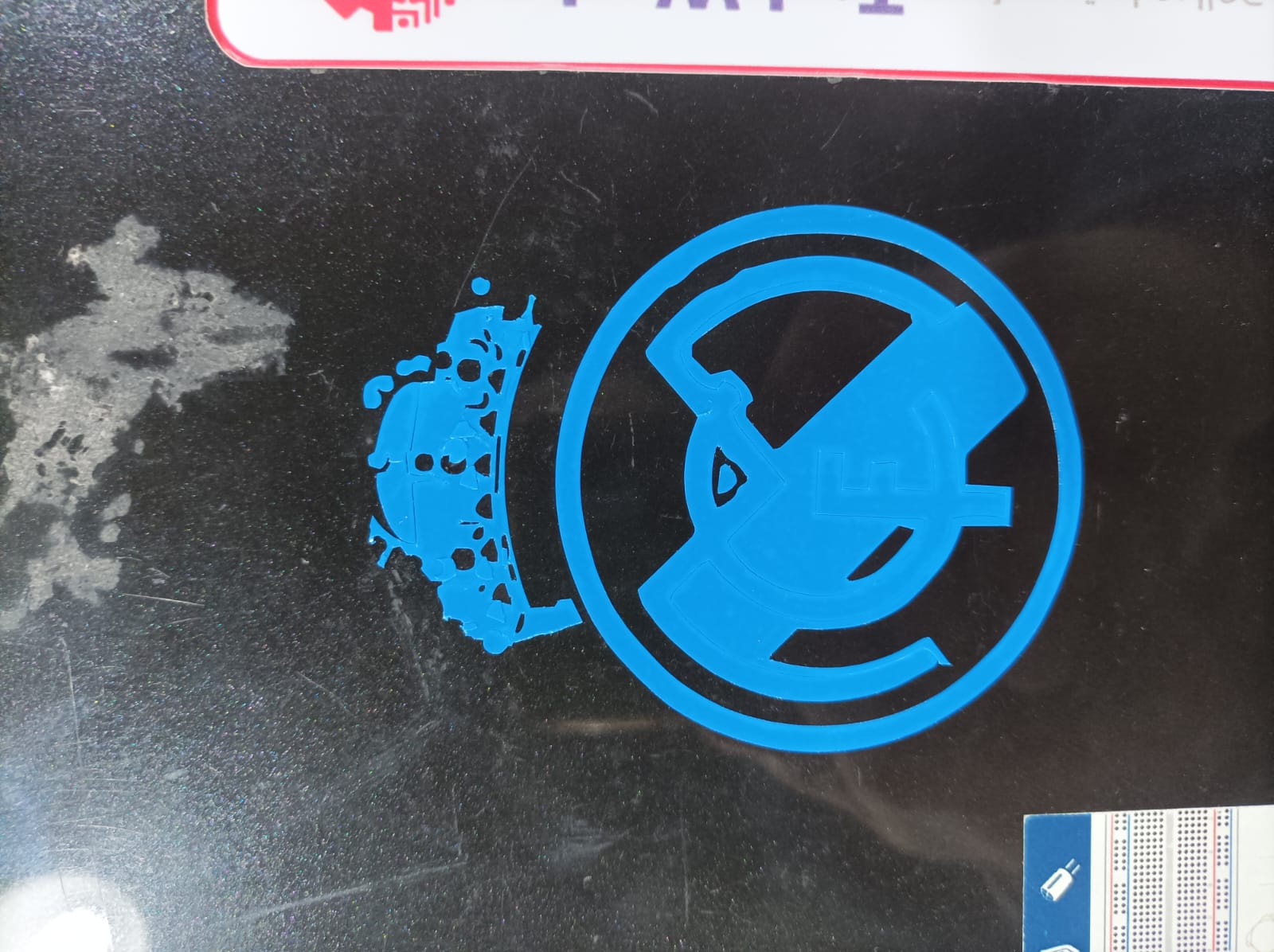
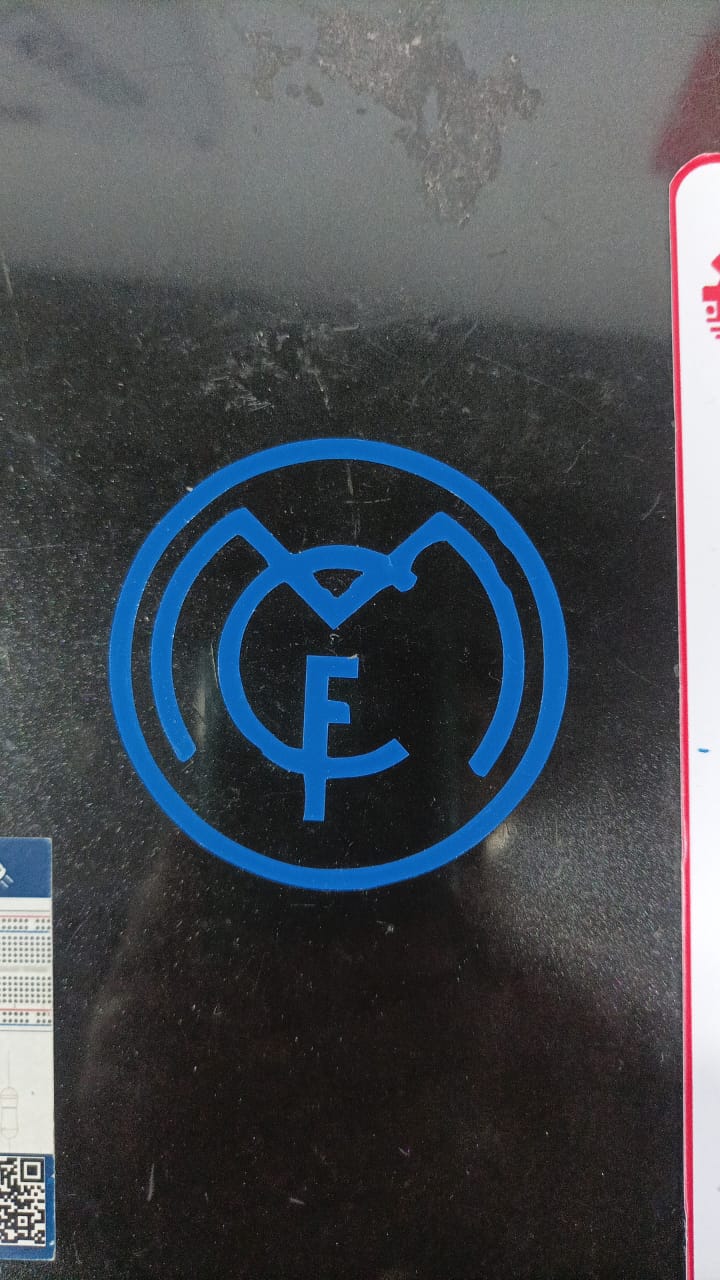
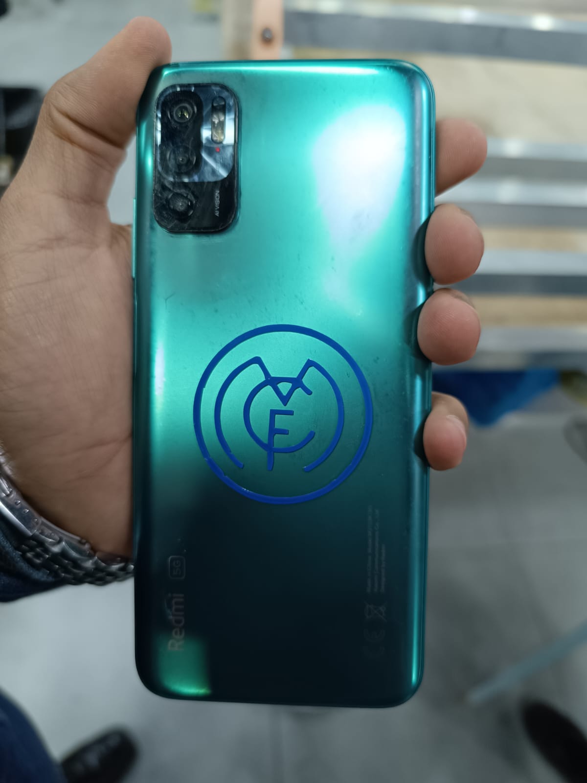
While attempting to create a Real Madrid sticker using a vinyl cutter, I encountered a problem related to weeding. Due to the intricate design of the Real Madrid logo, I found it challenging to weed the excess vinyl material accurately. Despite exercising precision and patience, I inadvertently removed some parts of the design, resulting in damage to the vinyl and compromising the sticker's quality. Additionally, I experienced tracking issues with the vinyl cutter, possibly due to improper loading of the vinyl material or misalignment of the cutter's rollers. As a consequence, the design appeared skewed and off-center, detracting from the overall aesthetic appeal of the sticker.