Input Devices
Group assignment
For the group assignment , the team worked with both analog and digital input devices to understand their signals.
Analog Signals:
Sensor:
The team selected an LDR (Light Dependent Resistor) sensor, which changes its resistance based on ambient light levels.
Observed Signals:
Using an oscilloscope, the team measured the output voltage of the LDR sensor in response to changes in ambient light. They connected the LDR sensor to a microcontroller board and observed the voltage changes when exposed to different light levels. This provided insights into how the sensor's resistance variation correlates with the amount of light it detects.
Digital Signals:
Sensor:
For digital signal measurement, the team utilized an ultrasonic distance sensor, which employs ultrasonic waves to measure distances.
Observed Signals:
Similarly, using an oscilloscope, the team measured the voltage output of the ultrasonic sensor to observe changes in voltage corresponding to different distances. This allowed them to understand how the sensor's digital output varies with proximity to objects.
Summary:
Through these experiments, the team gained practical insights into how both analog and digital sensors operate and how their signals behave in response to changing environmental conditions or distances to objects. This hands-on experience deepened their understanding of sensor technologies and their applications in various electronic projects.
Individual assignment
For my individual assignment, I'm diving into the world of sensors, aiming to understand how they work by connecting them to a development board. My focus is on learning how to link different sensors to the microcontroller and program it to gather data from them.
I've chosen multiple sensors for this project, each with its own unique functions. To make the integration process smoother, I'll be using a board I designed earlier. This board acts as a bridge between the sensors and the microcontroller, providing the necessary connections and interfaces.
The Seeed Xiao RP2040 microcontroller will be at the heart of this project, responsible for tasks like data collection and processing. Its compatibility with various sensors and user-friendly programming capabilities make it a perfect fit for what I aim to achieve.
Now, let's delve into the exciting journey of integrating each sensor with the development board and microcontroller to unlock their potential.
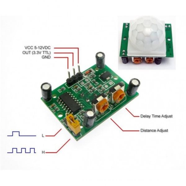
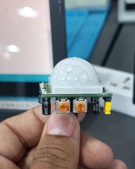
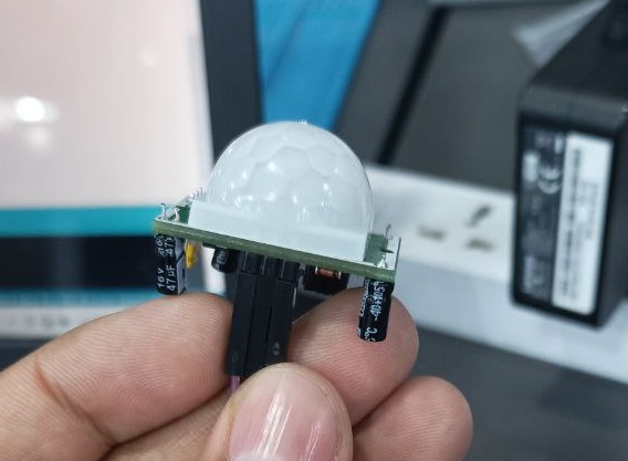
Sensor1: PIR sensor
Let's delve into the Passive Infrared (PIR) sensor, a fascinating device widely used for motion detection. Unlike many other sensors, PIR sensors don't emit any energy themselves; instead, they detect infrared radiation emitted by objects in their field of view.
The principle behind PIR sensors is based on the fact that all objects with a temperature above absolute zero emit infrared radiation. When an object moves within the detection range of a PIR sensor, it causes a change in the pattern of infrared radiation reaching the sensor.
Here's how it typically works:
Detection: The PIR sensor has two slots that detect infrared radiation. These slots are divided by a filter, which blocks out any ambient radiation not emitted by moving objects.
Sensing Motion: When an object moves within the sensor's field of view, it causes a change in the amount of infrared radiation reaching each slot. This change is detected by the sensor.
Output: The PIR sensor then sends a signal to the connected microcontroller, indicating that motion has been detected. This signal can trigger various actions, such as turning on lights, activating an alarm, or capturing images.
Adjustable Sensitivity and Range: PIR sensors often come with adjustable sensitivity and range settings, allowing users to customize their operation based on the specific requirements of the application.
Low Power Consumption: One of the significant advantages of PIR sensors is their low power consumption. They remain in a low-power standby mode until motion is detected, making them ideal for battery-powered applications such as security systems and motion-activated lighting.
When integrating a PIR sensor with a microcontroller, the process typically involves connecting the sensor's output pin to one of the microcontroller's digital input pins. Then, the microcontroller can be programmed to react to the signal received from the sensor, performing tasks based on the detected motion.
Overall, PIR sensors are versatile and widely used in various applications, including security systems, automatic lighting systems, and even in smart home devices. Their ability to detect motion accurately and efficiently makes them an indispensable component in many projects.
Here's the datasheet for a typical PIR sensor: PIR Motion Sensor Datasheet. Different PIR sensors may have slightly different pin configurations, so it's always good to refer to the specific datasheet for your sensor.
Assuming you are using a standard PIR sensor with three pins (VCC, OUT, GND), here's how you can connect it to the Seeed Xiao RP2040:
PIR Sensor Pin Configuration
- VCC: Power supply (usually 3.3V or 5V)
- OUT: Digital output
- GND: Ground
Seeed Xiao RP2040 Pin Configuration
Here's a simplified pinout of the Seeed Xiao RP2040 for reference:
- 3V3: 3.3V power output
- GND: Ground
- D0 - D9: Digital I/O pins
- A0 - A1: Analog I/O pins (also usable as digital pins)
Connecting the PIR Sensor to Seeed Xiao RP2040
- VCC (PIR) to 3V3 (Xiao): Connect the VCC pin of the PIR sensor to the 3.3V power output pin on the Xiao RP2040.
- GND (PIR) to GND (Xiao): Connect the GND pin of the PIR sensor to the Ground (GND) pin on the Xiao RP2040.
- OUT (PIR) to D2 (Xiao): Connect the OUT pin of the PIR sensor to one of the digital I/O pins on the Xiao RP2040, such as D2.
Example Circuit Diagram
plaintextPIR Sensor Seeed Xiao RP2040 ----------- ----------------- VCC ----> 3V3 GND ----> GND OUT ----> D2
Sample Code
Here's a basic example code to read the PIR sensor output and print the state to the serial monitor:
cppint pirPin = 2; // OUT pin connected to D2
void setup() {
pinMode(pirPin, INPUT);
Serial.begin(9600);
}
void loop() {
int pirState = digitalRead(pirPin);
if (pirState == HIGH) {
Serial.println("Motion detected!");
} else {
Serial.println("No motion.");
}
delay(1000); // Wait for 1 second before the next reading
}
This setup will allow the Seeed Xiao RP2040 to read the digital output from the PIR sensor and print whether motion is detected to the serial monitor.
I have used the design that I made in Week 8
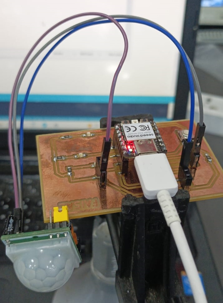
For the wires I connected the purple wire to the ground the grey wire to the pin 26 in the seeed xiao rp2040 and the blue wire to the 5 volt pin.
For motion detection, I've utilized a PIR motion sensor, and I've programmed an Arduino board to interpret the sensor signals and control the lighting accordingly. It's a straightforward setup that can make a big difference in terms of convenience and energy efficiency.
Microcontroller Programming
To begin programming your microcontroller, set up the Arduino IDE by selecting the appropriate board (Seeed Xiao RP2040) and port.
Code Structure:
Start by including the necessary libraries for analog input and serial communication.
Initialize variables and pins for sensor connection.
In the setup function, initialize serial communication and configure the sensor pin as an input.
In the loop function, use the analogRead() function to read the analog value from the sensor.
Print the sensor readings to the serial monitor for testing and debugging purposes.
Programming Logic:
Read the analog value from the sensor using the analogRead() function.
Convert the analog value to force or pressure units by applying appropriate calibration techniques.
Optionally, you can implement threshold detection or filtering algorithms to obtain more precise readings.
By following this structure and logic, you can effectively program your microcontroller to interface with the sensor and perform the desired tasks.
The code
cpp//the time we give the sensor to calibrate (10-60 secs according to the datasheet)
int calibrationTime = 30;
//the time when the sensor outputs a low impulse
long unsigned int lowIn;
//the amount of milliseconds the sensor has to be low
//before we assume all motion has stopped
long unsigned int pause = 5000;
boolean lockLow = true;
boolean takeLowTime;
int pirPin = 3; //the digital pin connected to the PIR sensor's output
int ledPin = 13;
/////////////////////////////
//SETUP
void setup(){
Serial.begin(9600);
pinMode(pirPin, INPUT);
pinMode(ledPin, OUTPUT);
digitalWrite(pirPin, LOW);
//give the sensor some time to calibrate
Serial.print("calibrating sensor ");
for(int i = 0; i < calibrationTime; i++){
Serial.print(".");
delay(1000);
}
Serial.println(" done");
Serial.println("SENSOR ACTIVE");
delay(50);
}
////////////////////////////
//LOOP
void loop(){
if(digitalRead(pirPin) == HIGH){
digitalWrite(ledPin, HIGH); //the led visualizes the sensors output pin state
if(lockLow){
//makes sure we wait for a transition to LOW before any further output is made:
lockLow = false;
Serial.println("---");
Serial.print("motion detected at ");
Serial.print(millis()/1000);
Serial.println(" sec");
delay(50);
}
takeLowTime = true;
}
if(digitalRead(pirPin) == LOW){
digitalWrite(ledPin, LOW); //the led visualizes the sensors output pin state
if(takeLowTime){
lowIn = millis(); //save the time of the transition from high to LOW
takeLowTime = false; //make sure this is only done at the start of a LOW phase
}
//if the sensor is low for more than the given pause,
//we assume that no more motion is going to happen
if(!lockLow && millis() - lowIn > pause){
//makes sure this block of code is only executed again after
//a new motion sequence has been detected
lockLow = true;
Serial.print("motion ended at "); //output
Serial.print((millis() - pause)/1000);
Serial.println(" sec");
delay(50);
}
}
}
Explanation:
Variables Initialization: Variables are defined to store calibration time, time of low impulse, pause duration, and flags for lock and low time.
Setup Function: Serial communication is initialized, pins are set as input and output, and the sensor is calibrated. Calibration involves waiting for the sensor to stabilize after power-on.
Loop Function:
- If motion is detected (PIR pin is high), the LED is turned on. If it's the first time detecting motion after a pause, the time is printed.
- If no motion is detected (PIR pin is low), the LED is turned off. If it's the first time detecting no motion after a period of motion, the end time is printed.
This code essentially monitors the PIR sensor's output and toggles the LED accordingly while also providing output to the serial monitor for debugging purposes.
Testing and Results for PIR Sensor using Arduino IDE
Testing Procedure:
Upload the Arduino sketch provided to the Seeed Xiao RP2040 microcontroller via the Arduino IDE.
Open the serial monitor in the Arduino IDE to monitor the sensor readings.
Trigger motion within the detection range of the PIR sensor by moving within its field of view.
Observe the serial monitor for notifications of motion detection and motion cessation.