Electronics production
To complete the group assignment effectively, you will need to follow these steps:
First off, when we're doing our own PCB production, we've got this cool Roland SRM-20 milling machine. It's got a decent work area, and it can spin its cutting tool pretty fast, between 3,000 to 7,000 RPM. We use a software called Mods to generate the cutting paths. Safety's a big deal, so we always make sure to follow Murad's instructions before getting started.
Now, when we're ready to mill, we set up the machine carefully. We pick the right cutting bit, attach the material securely to the machine bed with double-sided tape, and make sure everything's aligned just right. Then, we set our cutting parameters. For trace milling, we go at about 4 mm/s with a really small depth of cut, like 0.15 mm, using a tiny 1/64 inch bit. For cutting the outline, we use similar settings but with a slightly thicker 1/32 inch bit.
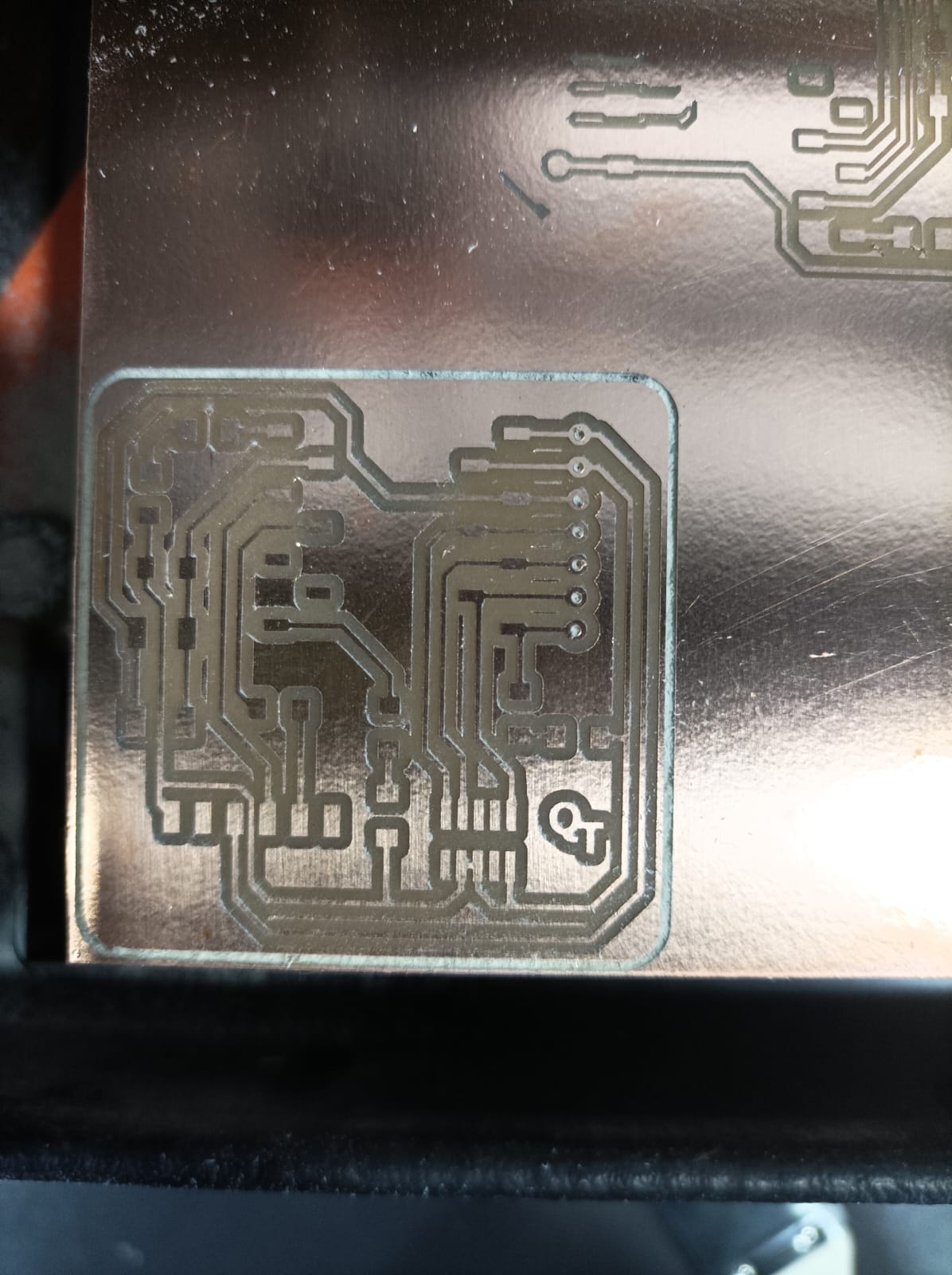
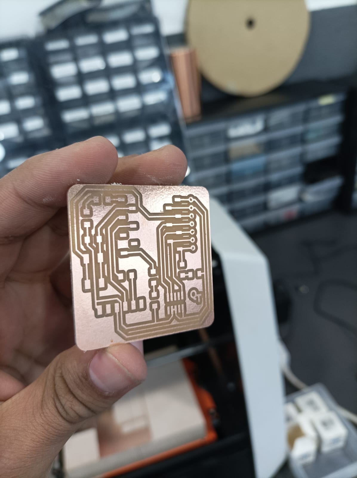
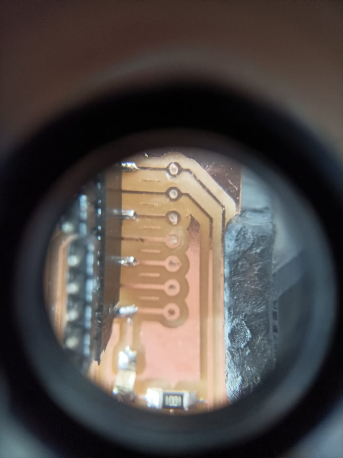
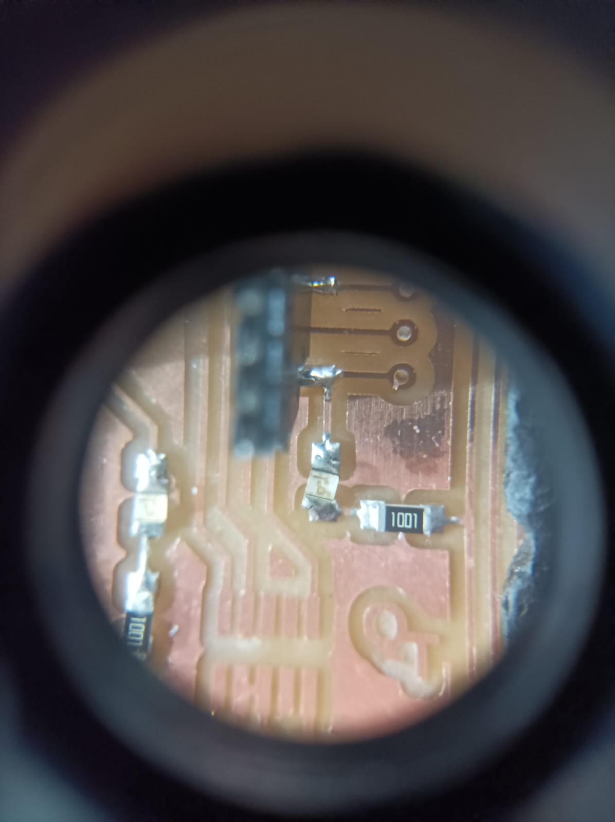
After milling, we inspect our work closely. Usually, everything looks pretty good, but sometimes we notice some rough edges, especially if the cutting tool's getting worn out. If we spot any burrs or rough spots, we clean them up carefully with a metal edge.
Alright, now let's say we've got a project where we need more professional-looking PCBs or maybe a larger quantity. That's when we turn to a board house like JLCPCB. The process is pretty straightforward. We log into our account, upload our Gerber files, specify the details like quantity and PCB thickness, review the order, and then make the payment. JLCPCB takes it from there, manufacturing and shipping the PCBs to us. We can track the progress through our account until they arrive at our doorstep.
One thing to remember is to make sure our design follows JLCPCB's guidelines to avoid any hiccups during manufacturing. And if we're ever unsure about anything, there's always FAQs and support docs to help us out.
So that's the deal with making PCBs in-house and sending them off to the pros. It's all about safety, precision, and knowing when to DIY and when to call in the experts.
Individual assignment
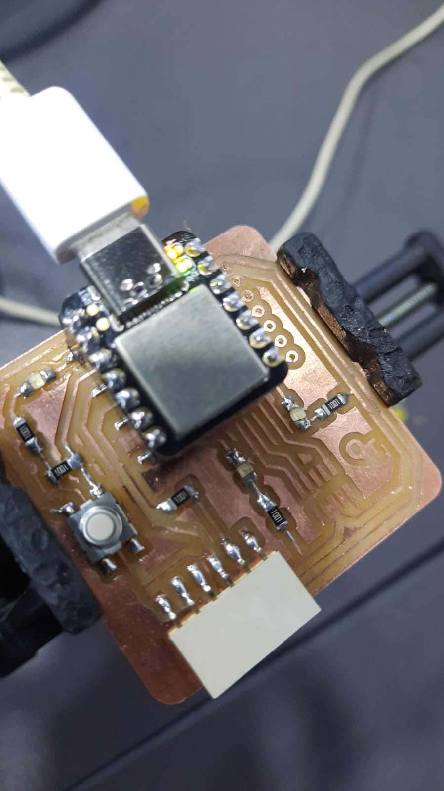
In this week we were asked to use Roland monoFab SRM-20 in our lab and use already design in microcontroller development board and I have chosen the version two as follows
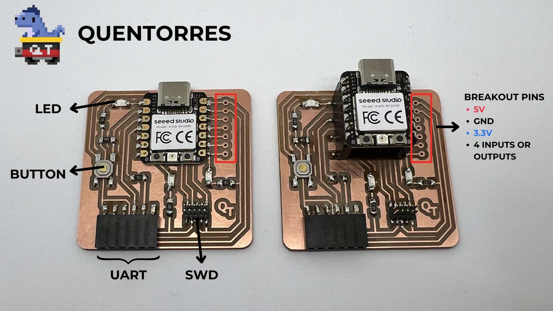
I have chosen the right one
Unfortunately there were no more xiao rp2040 in our lab but we have Seeed studio XIAO SAMD21 and the procedure of how to use it is different than using xiao rp2040
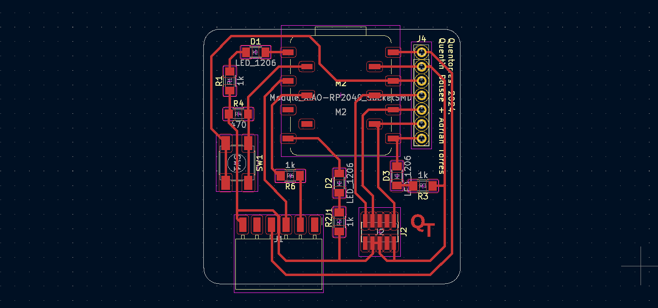
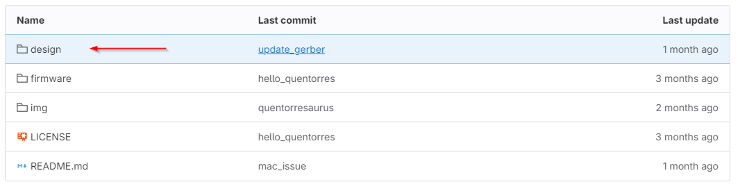
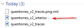
Go to design file
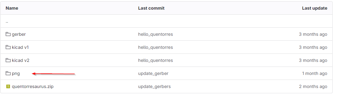
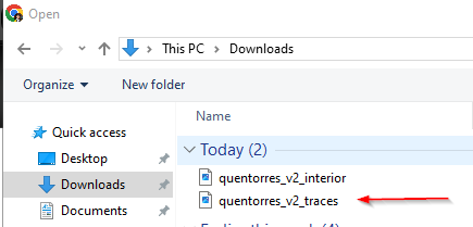
Go to png file
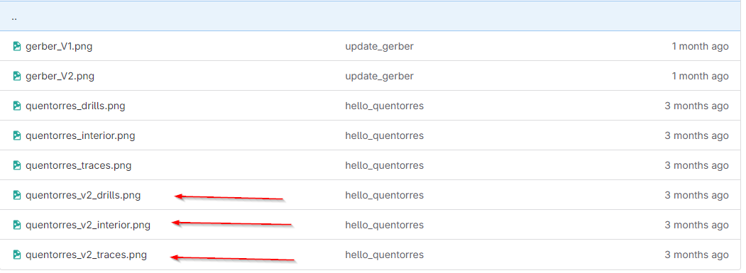
You will see the the pictures of the design version two download them
Then go to mods project website to start our journey to create the pcb. (link)

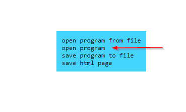
Choose programs
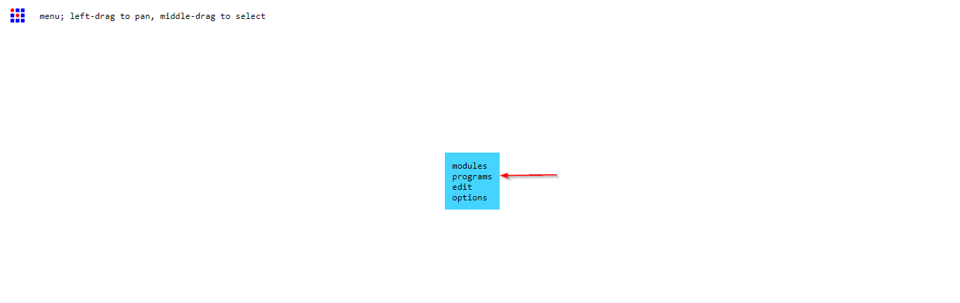
Choose open program
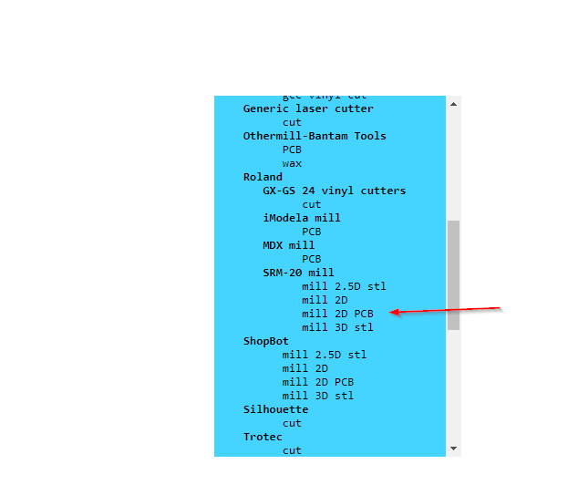
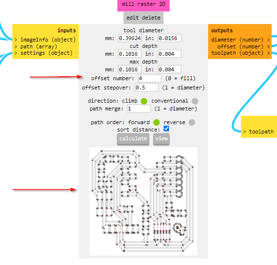
Scroll down till you find SRM 20 mill 2D PCB
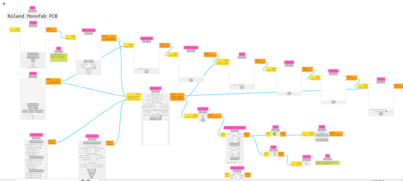
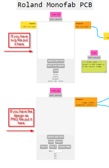
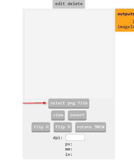
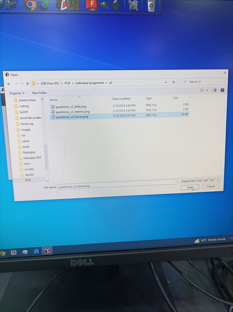
In the top left you will see the place where ypu have to put the png file ofcourse you will put one not all togather be carful.
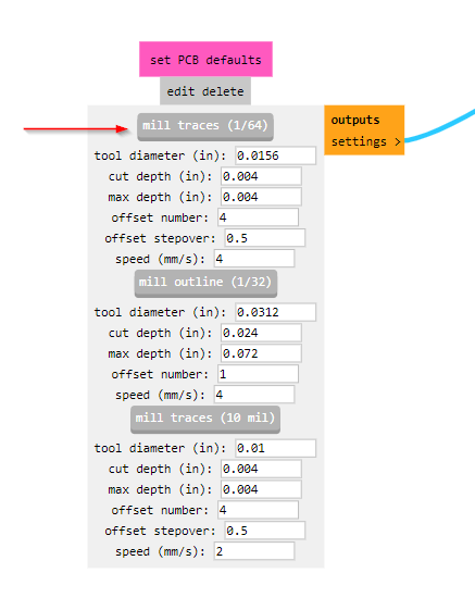
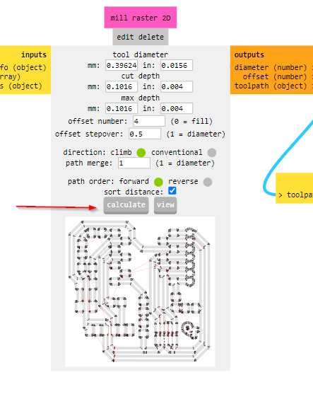
Since we want to make traces we must be carful to choose the tool here we have to choose the 1/64 tool.
Here press calculate to start creating the code to put in the machine.
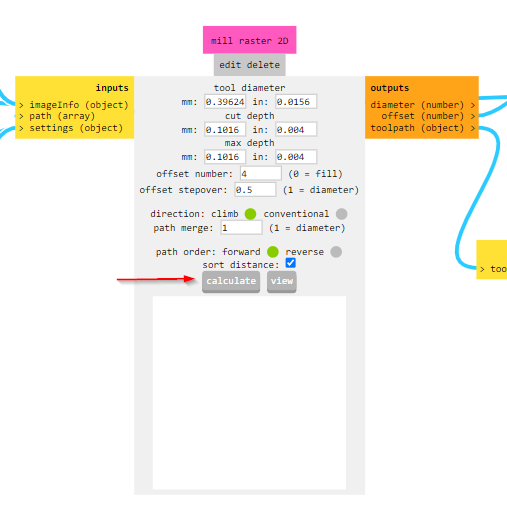
Here you can see the way the machine will behave when cutting the traces.
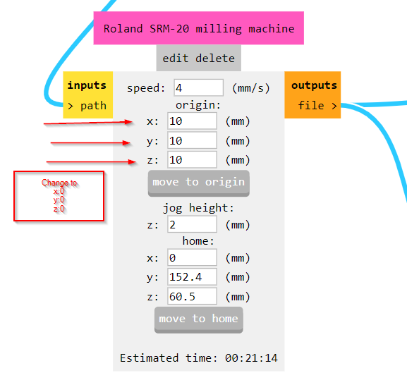
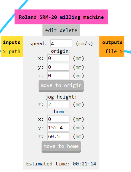
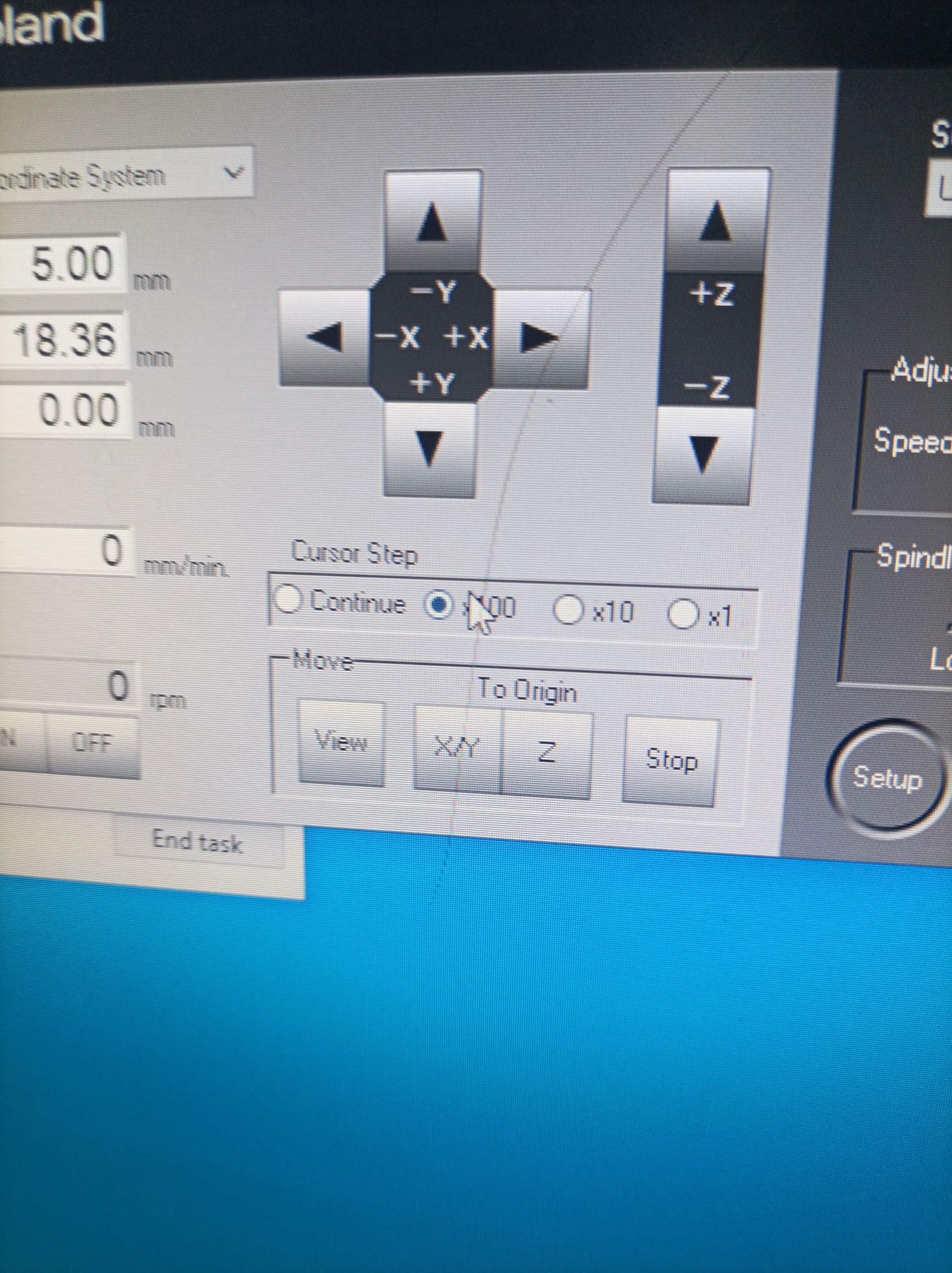
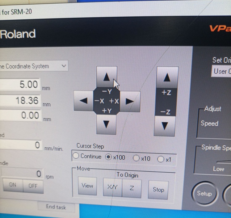
Be sure to make this part all zero so you can control the machine and determine your x, y and z axis.
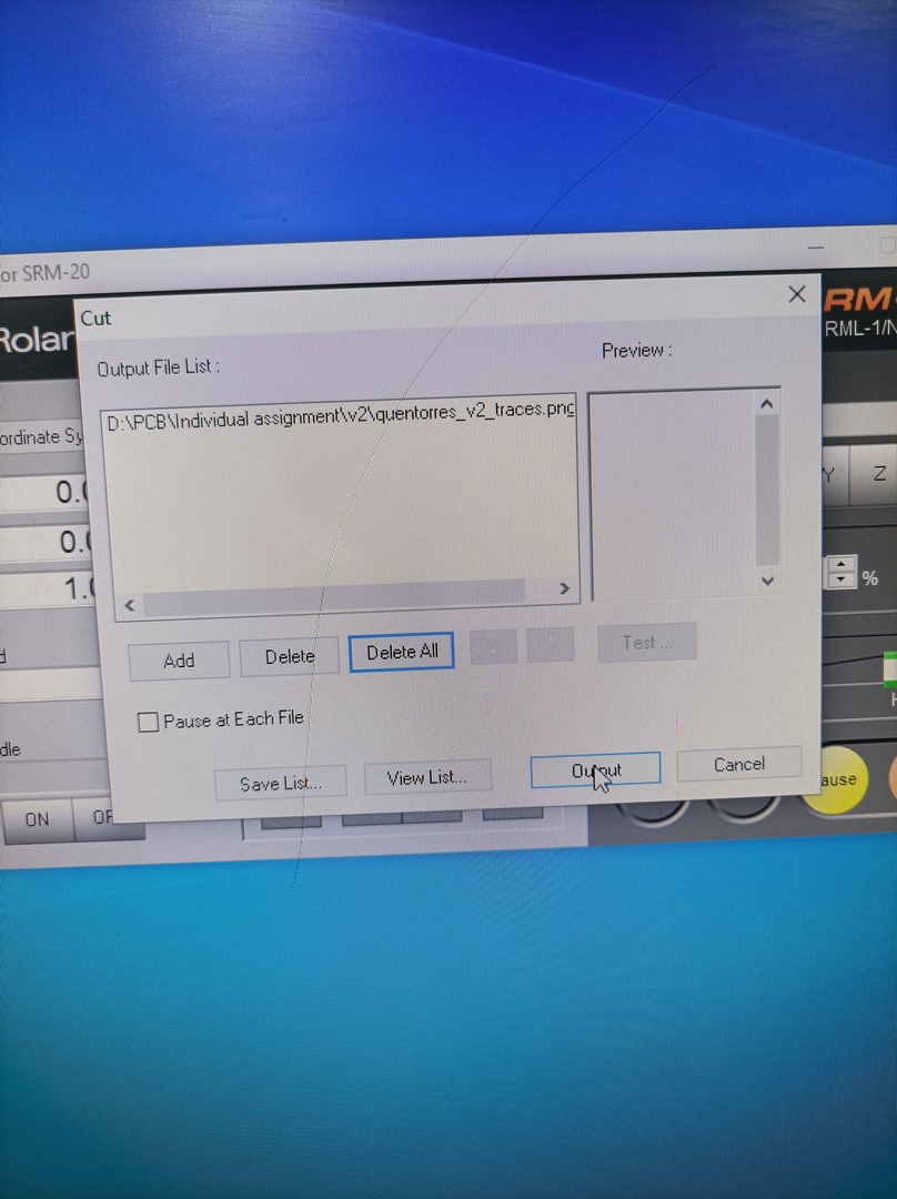
Here change where the file is created to save in your device or your laptop.
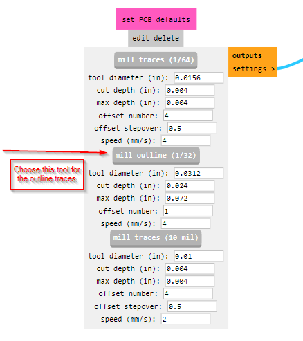
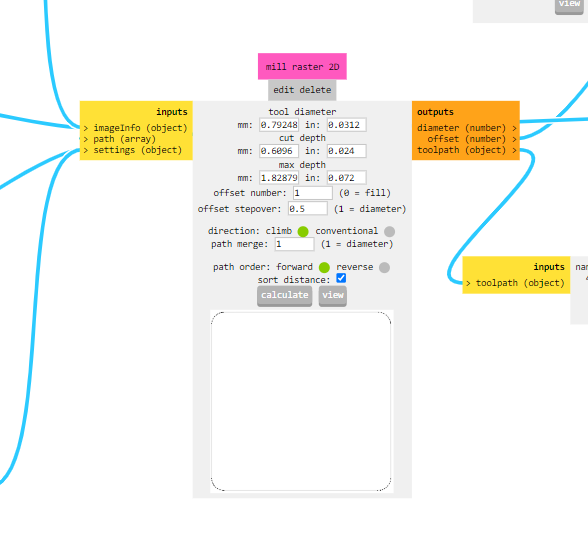
Repeat it to the outline png.
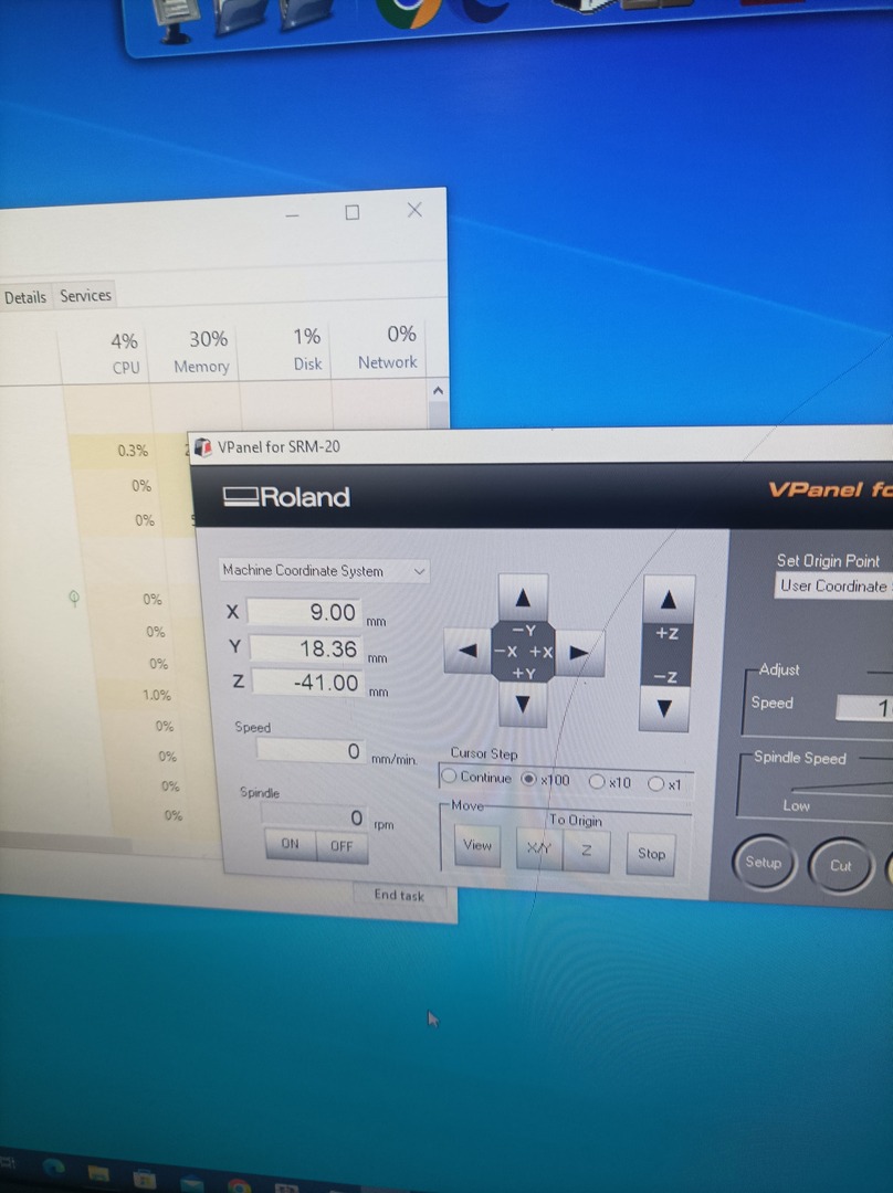
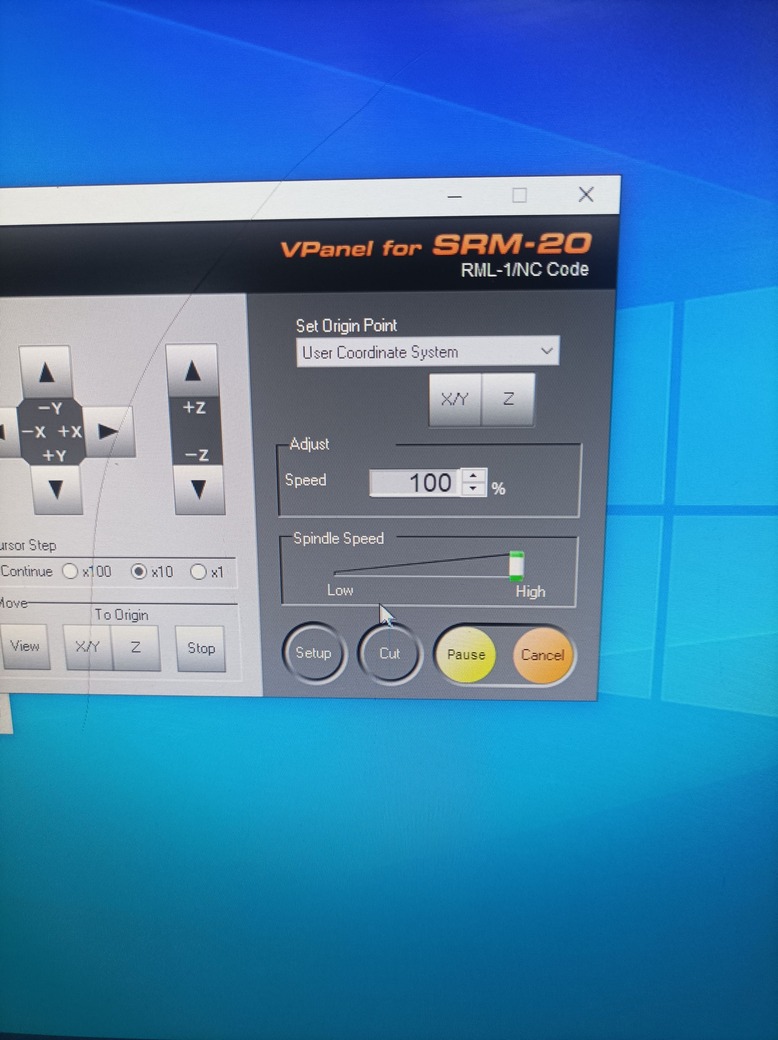
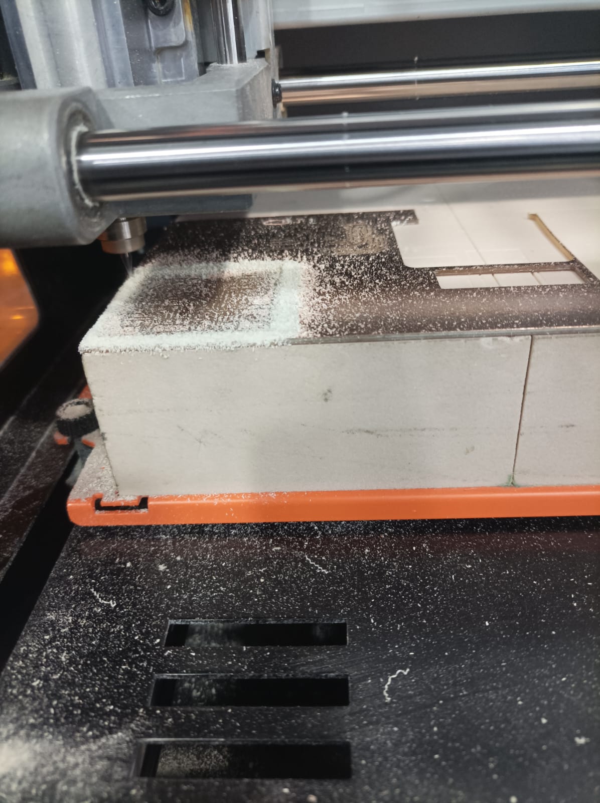
Here I setup my machine and put my position of the tool to start milling.
To program the Xiao board using the Arduino IDE, you'll need to install the appropriate board definitions and drivers.
Here are the general steps to install the board definitions for the Xiao board in the Arduino IDE:
- Open the Arduino IDE.
- Go to File > Preferences (on Windows) or Arduino > Preferences (on macOS).
- In the "Additional Board Manager URLs" field, add the following URL if it's not already present:
https://files.seeedstudio.com/arduino/package_seeeduino_boards_index.json - Click "OK" to close the Preferences window.
- Go to Tools > Board > Boards Manager.
- In the Boards Manager window, type "Seeed SAMD Boards" in the search bar.
- Click on the "Seeed SAMD Boards" entry, and click the "Install" button.
- Once the installation is complete, close the Boards Manager window.
After installing the board definitions, you should be able to select the Seed Studio Xiao board from the Tools > Board menu in the Arduino IDE and proceed with uploading sketches to it.
As for drivers, the Xiao board should use the built-in USB CDC (Communications Device Class) drivers provided by the Arduino IDE for communicating with your computer. Usually, when you connect the Xiao board to your computer via USB for the first time, it should automatically install the necessary drivers. However, if you encounter driver issues, you may need to check the official documentation or forums provided by Seed Studio for any specific driver installation instructions or troubleshooting tips.
Always make sure you are referring to the latest documentation and resources provided by Seed Studio for the most up-to-date information on using the Xiao board with the Arduino IDE.
cppvoid setup() {
// Initialize the digital pin D0 as an output.
pinMode(D0, OUTPUT);
}
void loop() {
// Turn the LED on (HIGH is the voltage level)
digitalWrite(D0, HIGH);
// Wait for a second
delay(1000);
// Turn the LED off by making the voltage LOW
digitalWrite(D0, LOW);
// Wait for a second
delay(1000);
}
Explanation:
- setup(): This function runs once when you press reset or power the board. Here, we set pin D0 as an output.
- loop(): This function runs over and over again, forever. We turn the LED on (by setting the pin high), wait for one second, turn the LED off (by setting the pin low), and wait for one second again. This creates a blinking effect.
Steps to Upload the Code:
- Open Arduino IDE: Make sure you have the latest version of the Arduino IDE installed.
- Select the Board: Go to
Tools>Boardand select the appropriate Seeed SAMD board. - Select the Port: Go to
Tools>Portand select the port to which your board is connected. - Upload the Code: Click the upload button (right arrow) in the Arduino IDE to upload the code to your board.
Connect the LED:
- Anode (long leg) to D0: Connect the longer leg of the LED to pin D0.
- Cathode (short leg) to GND: Connect the shorter leg of the LED to the ground (GND).
Make sure to use a current-limiting resistor (e.g., 220 ohms) in series with the LED to prevent it from burning out.