Computer-Aided Design
Computer Aided Design (CAD) is a computer technology used to design and develop products and systems. It has revolutionized the design and engineering industries by providing a more efficient, precise, and cost-effective way to bring ideas to life. Learning how to use computer-aided design (CAD) software will open up a world of possibilities for bringing your design ideas to life. Here are some steps you can take to get started:
- Choose a CAD Software.
- Learn the Basics.
- Practice Regularly.
- Explore Advanced Features.
- Seek Resources and Support.
Remember, learning CAD software is a continuous process, so don't be discouraged by setbacks or challenges. With dedication, patience, and practice, you'll be able to create stunning designs and bring your ideas to life with confidence. Good luck on your CAD journey!
2D Design - Vector vs. Raster Graphics
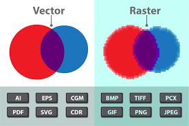
What are Vector Graphics? vector graphics are created using commands to form shapes, while raster graphics are made up of individual pixels. Vector graphics are best for non-photographic uses because they provide clean lines at any size, although they have limitations such as less detail in color shading. The choice between vector and raster graphics depends on personal preferences and specific use cases.
One of the softwares that could be used to make vector graphics is inkscape,it's free software and user-friendly, plus there are many youtube tutorials on it. So I just downloaded it and then opened it as shown below:
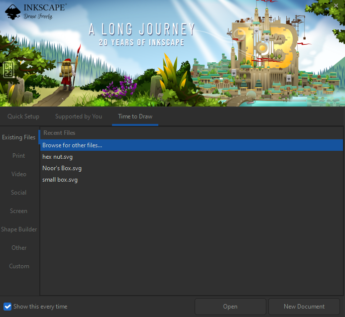
Then choose new document to start your journey!
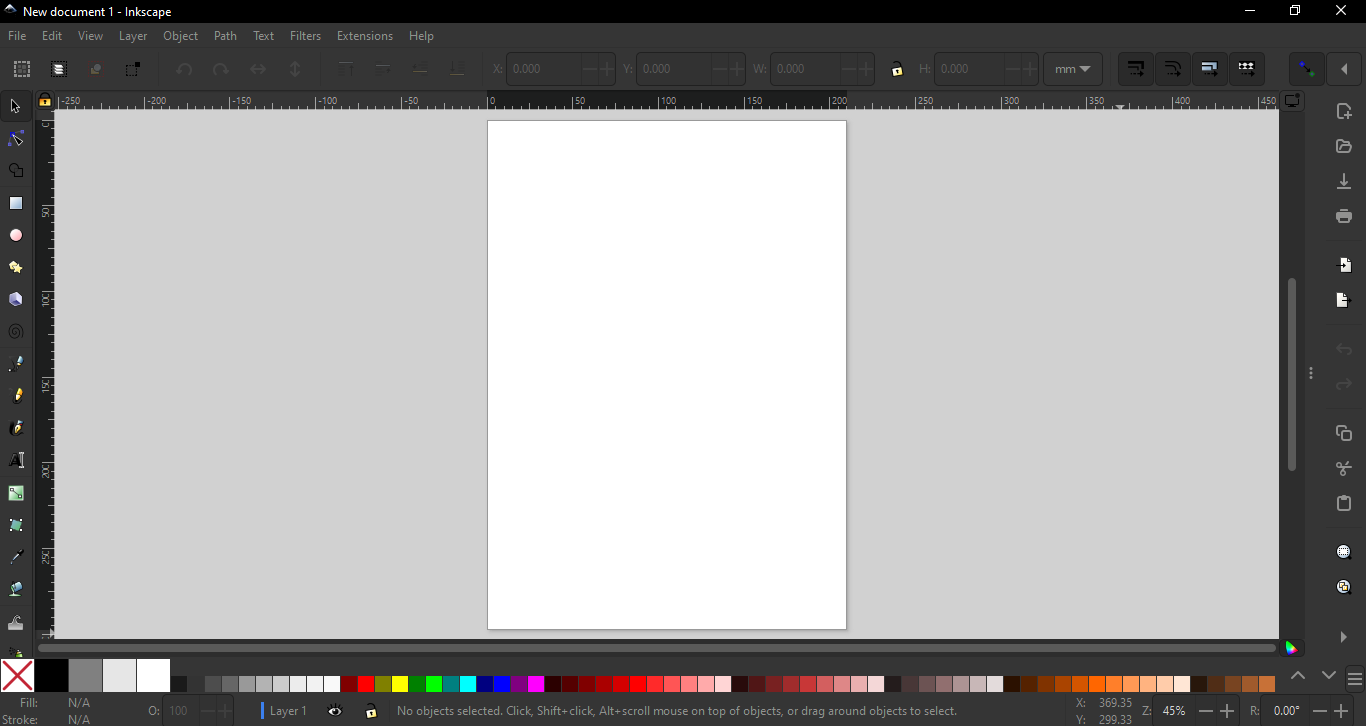
You can these commands to draw lines, circles, sequares, regtangles and even hexagonal.
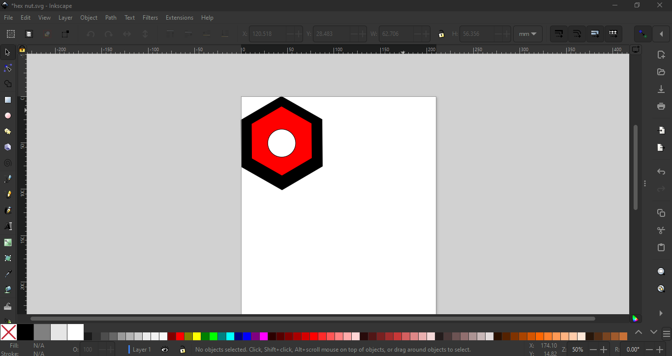
I have drawn a hexagonal to draw a hex nut and to draw a hex nut in Inkscape:
- Open Inkscape and create a new document.
- Select the "Polygon" tool.
- Click on the canvas and, in the dialogue that appears, choose "Corners: 6" for a hexagon.
- Draw the hexagon.
- Use the "Edit Paths by Nodes" tool to adjust the size if needed.
- Duplicate the hexagon (Ctrl + D).
- Resize the duplicated hexagon to make it smaller.
- Align the smaller hexagon to the center of the larger one.
- Now, draw a small circle in the center using the "Ellipse" tool.
And the final result is as below
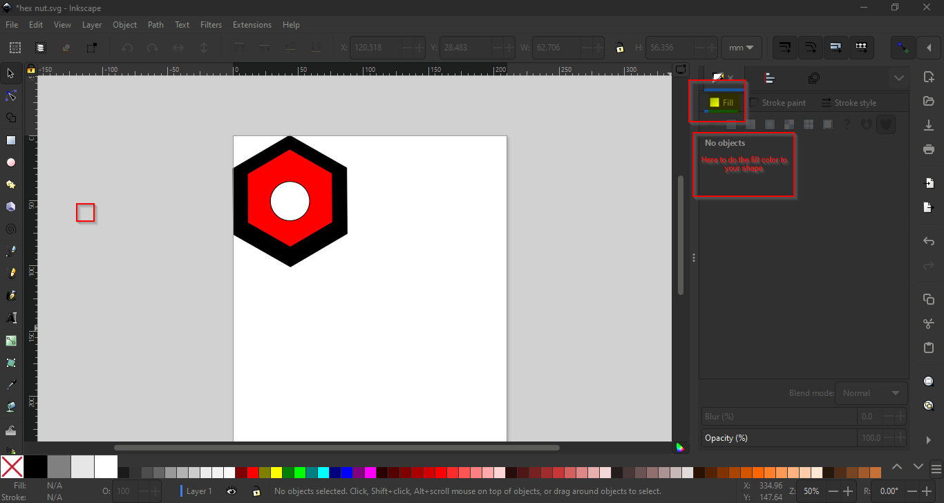
In Inkscape, a popular open-source vector graphics editor, the "Fill" and "Stroke" commands are fundamental tools used to control the appearance of shapes and paths in your drawings. Here's an explanation of each:
Fill: The "Fill" refers to the interior color or pattern of a shape or path. When you create a shape or draw a path in Inkscape, it is initially filled with a default color (usually black or white). However, you can change the fill color or apply a gradient, pattern, or even no fill at all.
To change the fill color:
- Select the object or shape you want to modify.
- Use the Fill and Stroke panel, which you can access by going to "Object" > "Fill and Stroke" or by pressing
Shift+Ctrl+F. - In the Fill tab of the panel, choose a color from the color palette or specify a custom color using the color picker.
Additionally, you can apply gradients, patterns, or even apply a transparent fill by adjusting the settings in the Fill tab.
Stroke: The "Stroke" refers to the outline or border of a shape or path. It defines the visual appearance of the edge of the shape or path. Like the fill, the stroke can be customized with different colors, thicknesses (stroke width), and styles (such as dashed or dotted lines).
To change the stroke properties:
- Select the object or shape you want to modify.
- Use the Fill and Stroke panel (
Shift+Ctrl+F) or go to "Object" > "Fill and Stroke". - In the Stroke paint tab of the panel, choose a color from the color palette or specify a custom color using the color picker.
- In the Stroke style tab, adjust the stroke width (thickness), style (solid, dashed, dotted, etc.), and other properties.
You can also control the alignment of the stroke relative to the path (centered, inside, or outside) and apply markers (such as arrowheads) to the start and end of the stroke.
By understanding and utilizing the Fill and Stroke commands effectively, you can create visually appealing and customizable vector graphics in Inkscape, allowing you to express your creativity and achieve the desired look for your designs.
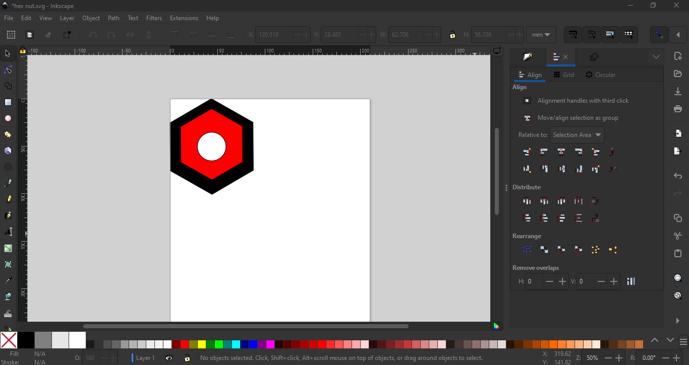
In Inkscape, the "Align and Distribute" command is a powerful tool that helps you precisely position and arrange objects within your drawings. It allows you to align objects relative to each other or distribute them evenly along a specified axis. Here's how it works:
Align: The Align feature in Inkscape lets you position objects relative to each other along different axes (horizontal or vertical) or align them based on their edges or centers.
To align objects:
- Select the objects you want to align.
- Open the Align and Distribute panel by going to "Object" > "Align and Distribute" or pressing
Shift+Ctrl+A. - In the panel, you'll see options to align objects left, right, top, bottom, center horizontally, or center vertically.
- Click on the appropriate alignment buttons to align the selected objects according to your preference.
Distribute: The Distribute feature in Inkscape allows you to evenly distribute selected objects along a specified axis (horizontal or vertical).
To distribute objects:
- Select the objects you want to distribute.
- Open the Align and Distribute panel (
Shift+Ctrl+A). - In the panel, you'll find options to distribute objects horizontally or vertically.
- You can choose to distribute the objects with equal spacing between them or distribute them based on their centers or edges.
Additionally, you can specify the amount of space between the objects by adjusting the spacing values in the panel.
By using the Align and Distribute command effectively, you can ensure that objects within your drawings are neatly organized and evenly spaced, resulting in professional-looking designs. Whether you're working on logos, illustrations, diagrams, or other types of vector graphics, mastering the Align and Distribute feature in Inkscape will help you achieve precise and visually pleasing layouts.
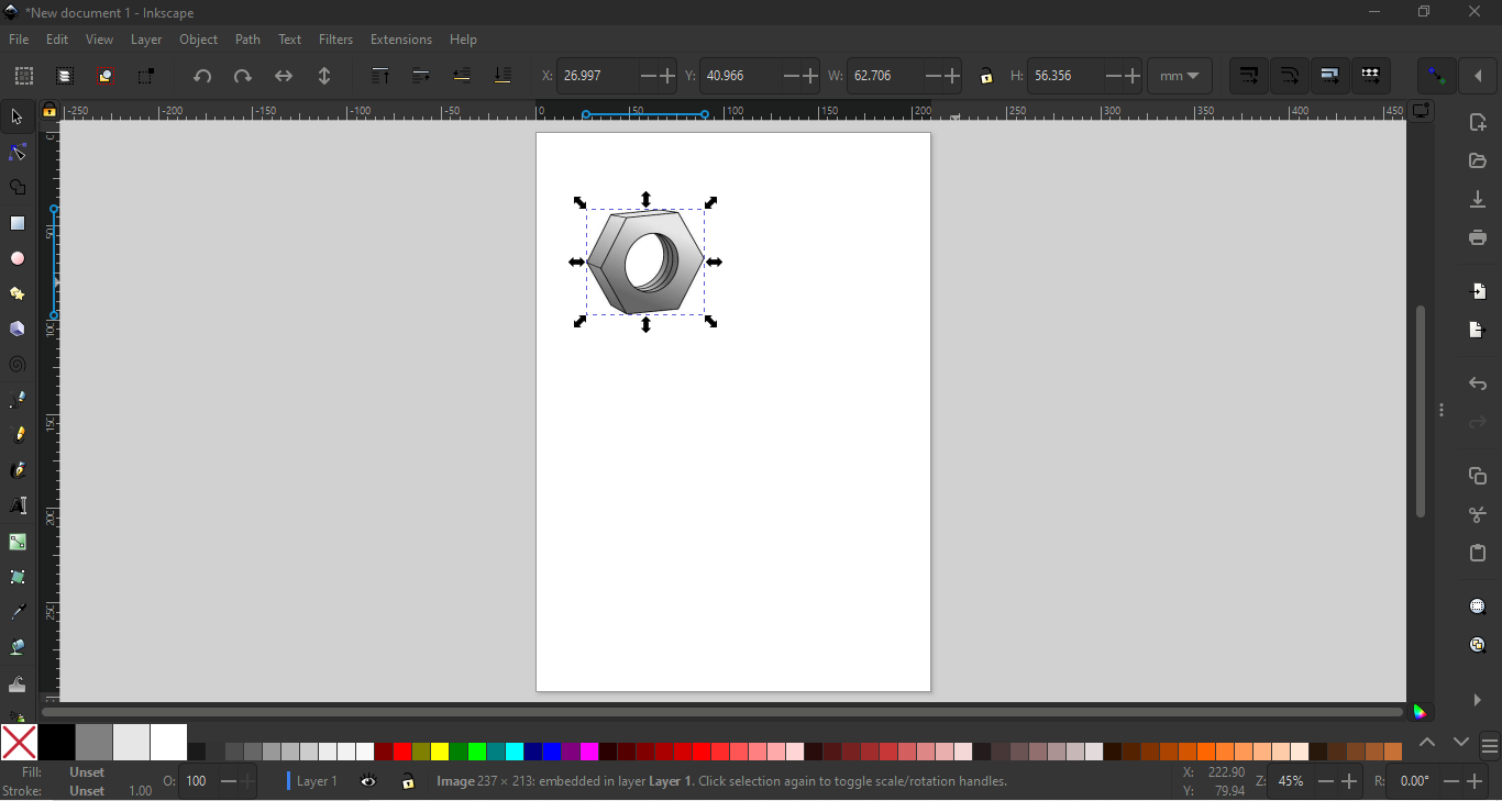
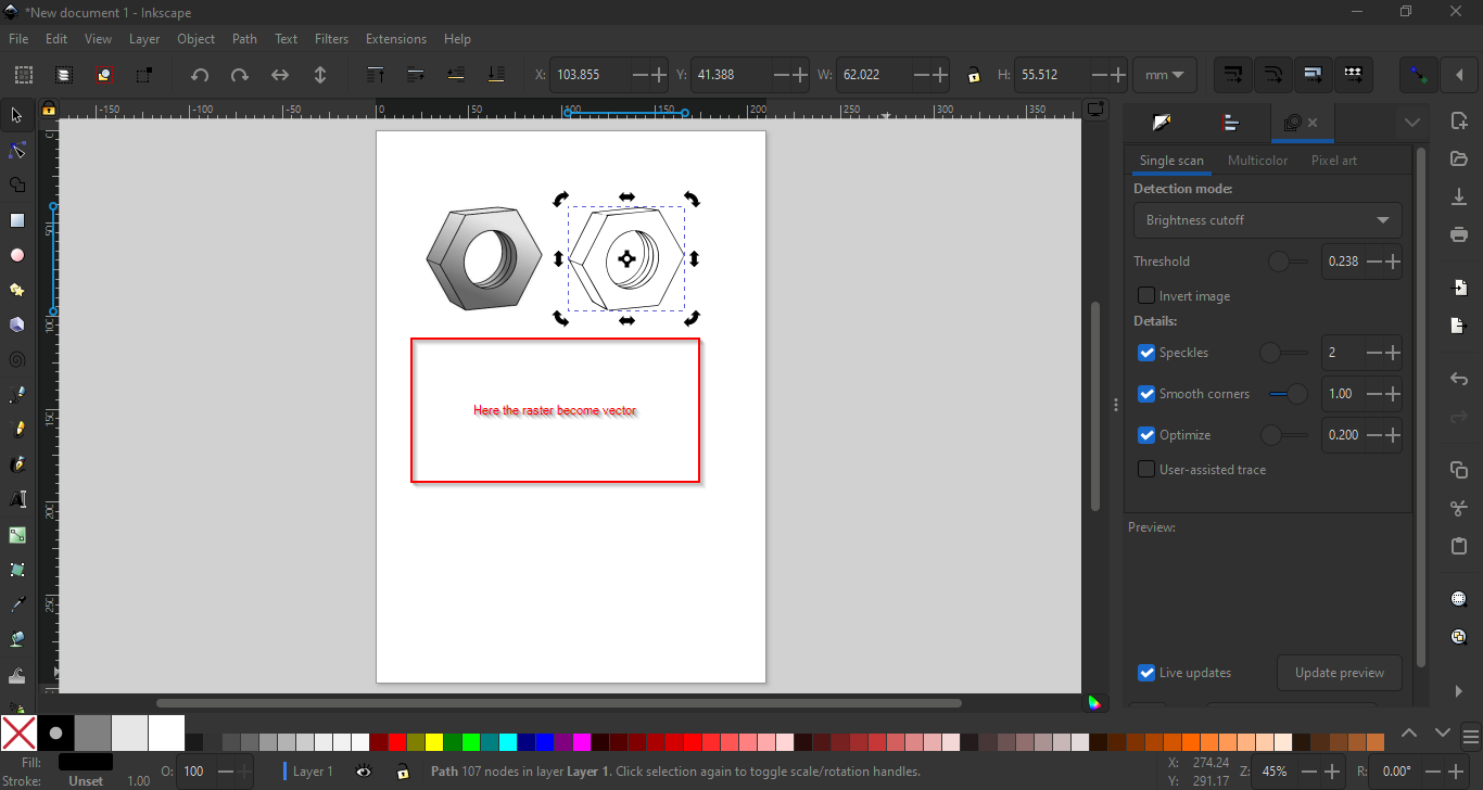
In Inkscape, converting a raster image to a vector format involves using the "Trace Bitmap" feature. Here's a step-by-step guide:
Import the Raster Image: Open Inkscape and import the raster image you want to convert to vector format. You can do this by clicking on "File" > "Import" and selecting your image file.
Select the Image: Click on the raster image to select it.
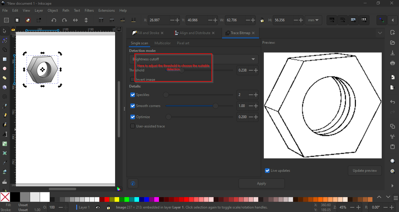
Access the Trace Bitmap Tool: Go to the "Path" menu at the top of the screen and choose "Trace Bitmap." Alternatively, you can press Shift+Alt+B on your keyboard.
Configure Trace Bitmap Settings: A dialog box will appear with options for tracing. Here are some key settings you can adjust:
- Brightness Cutoff: Determines the threshold for what is considered black and what is considered white. Adjust this slider to fine-tune the tracing process.
- Multiple Scans: You can choose between several different tracing methods such as "Brightness Cutoff," "Edge Detection," etc.
- Smooth: This option smoothens the traced paths.
Preview: After adjusting the settings, you can click on the "Update" button to see a preview of how the traced image will look.
Apply the Trace: Once you are satisfied with the preview, click "OK" to apply the trace.
Review and Edit: After the trace is complete, you will have a vectorized version of your raster image. You may need to clean up and edit the vector paths as needed using the node tool and other editing tools in Inkscape.
Save Your Vector Image: Once you are satisfied with the vectorized image, save your work in a vector format such as SVG or PDF.
By following these steps, you can convert a raster image to a vector format using Inkscape's "Trace Bitmap" feature. Keep in mind that the quality of the vectorization may vary depending on the complexity and quality of the original raster image.
How to Create a Logo in Inkscape
Open Inkscape:
- Launch Inkscape on your computer.
Set Up Your Document:
- Go to
File > Newto create a new document. - Adjust the document size if necessary by going to
File > Document Properties.
- Go to
Select the Text Tool:
- In the toolbox on the left, select the Text Tool, which looks like the letter "A" (
Ton the keyboard).
- In the toolbox on the left, select the Text Tool, which looks like the letter "A" (
Create Text:
- Click on the canvas where you want to place your text.
- Type the first letter of your first name (e.g.,
F).
Change Font Family:
- With the text selected, go to the toolbar at the top and find the font dropdown menu.
- Select
Vladimir Scriptfrom the list of available fonts.
Create Another Text:
- Click again on the canvas, possibly below or next to the first letter, and type the first letter of your last name (e.g.,
A). - Again, select
Vladimir Scriptfrom the font dropdown menu.
- Click again on the canvas, possibly below or next to the first letter, and type the first letter of your last name (e.g.,
Adjust Size and Position:
- Use the Select Tool (the arrow icon or press
S) to move, resize, and position the letters to your liking. - You can click and drag the corners of the text box to resize the letters proportionally.
- Use the Select Tool (the arrow icon or press
Customize the Text:
- With the text selected, you can change the color by going to the Fill and Stroke dialog (
Object > Fill and Strokeor pressShift+Ctrl+F). - Adjust the fill color, stroke color, and stroke width as desired.
- With the text selected, you can change the color by going to the Fill and Stroke dialog (
Align and Distribute:
- To ensure your letters are perfectly aligned, use the Align and Distribute dialog (
Object > Align and Distributeor pressShift+Ctrl+A). - Select both letters and use the alignment options to center them vertically or horizontally.
- To ensure your letters are perfectly aligned, use the Align and Distribute dialog (
Save Your Work:
- Save your logo by going to
File > Save Asand choose a file format like SVG for vector graphics or PNG for raster images.
- Save your logo by going to
Summary
In summary, to create your logo in Inkscape, you used the Text Tool to write the first letter of your first name (F) and the first letter of your last name (A). You then selected the Vladimir Script font family to style your text, adjusted the size and position, customized the colors, and saved your work.
Feel free to add any specific details or personal touches you made during the process.
I loved inkscape it is a friendly software and easily to deal with it and the most of the problem that I faced can be easily solved.
How to Create a Logo in GIMP
Downloading and Installing GIMP
Download GIMP:
- Go to the official GIMP website: https://www.gimp.org/downloads/
- Click on the download link for your operating system (Windows, macOS, or Linux).
Install GIMP:
- Once the download is complete, open the installer file.
- Follow the on-screen instructions to install GIMP on your computer.
Creating a Logo in GIMP
Open GIMP:
- Launch GIMP from your applications menu or desktop shortcut.
Set Up Your Document:
- Go to
File > Newto create a new document. - In the dialog box, set your desired width and height for the logo, then click
OK.
- Go to
Select the Text Tool:
- In the toolbox on the left, select the Text Tool (the icon with a letter "A") or press
Ton your keyboard.
- In the toolbox on the left, select the Text Tool (the icon with a letter "A") or press
Create Text:
- Click on the canvas where you want to place your text.
- Type the first letter of your first name, which is
F.
Change Font Family:
- In the Text Tool options, which appear below the toolbox or in a separate dialog, find the font dropdown menu.
- Select
Vladimir Scriptfrom the list of available fonts. If you don't see the font, make sure it is installed on your system.
Adjust Text Size and Position:
- While the text is still selected, you can adjust the size using the size option in the Text Tool options.
- Use the Move Tool (press
Mor select the four-arrow icon) to position the text on the canvas.
Create Another Text:
- Click on the canvas again to create a new text box.
- Type the first letter of your last name, which is
A. - Repeat steps 5 and 6 to style and position this text.
Customize the Text:
- With the text selected, you can change the color by clicking on the color box in the Text Tool options.
- Choose your desired color from the color dialog that appears.
Align and Distribute:
- To ensure your letters are perfectly aligned, use the alignment tools.
- Go to
Layer > Align Layers, or use the Align Tool from the toolbox (it looks like a small rectangle with two arrows pointing in opposite directions). - Select both text layers and use the alignment options to center them vertically or horizontally.
Merge Layers:
- Once you are happy with the positioning, you can merge the text layers if needed.
- Right-click on each text layer in the Layers dialog and choose
Merge Down.
Save Your Work:
- Save your logo by going to
File > Export As. - Choose a file format like PNG for transparency or JPG for a non-transparent background.
- Name your file, choose the location, and click
Export.
- Save your logo by going to
By following these steps, you can create a simple and elegant logo using GIMP. Happy designing!
I did not like the software I did not know how to deal with it easily I felt it was harder than inkscape.
3-D Design
I will start learning about Fusion 360. I have just installed it directly from the website as shown below:
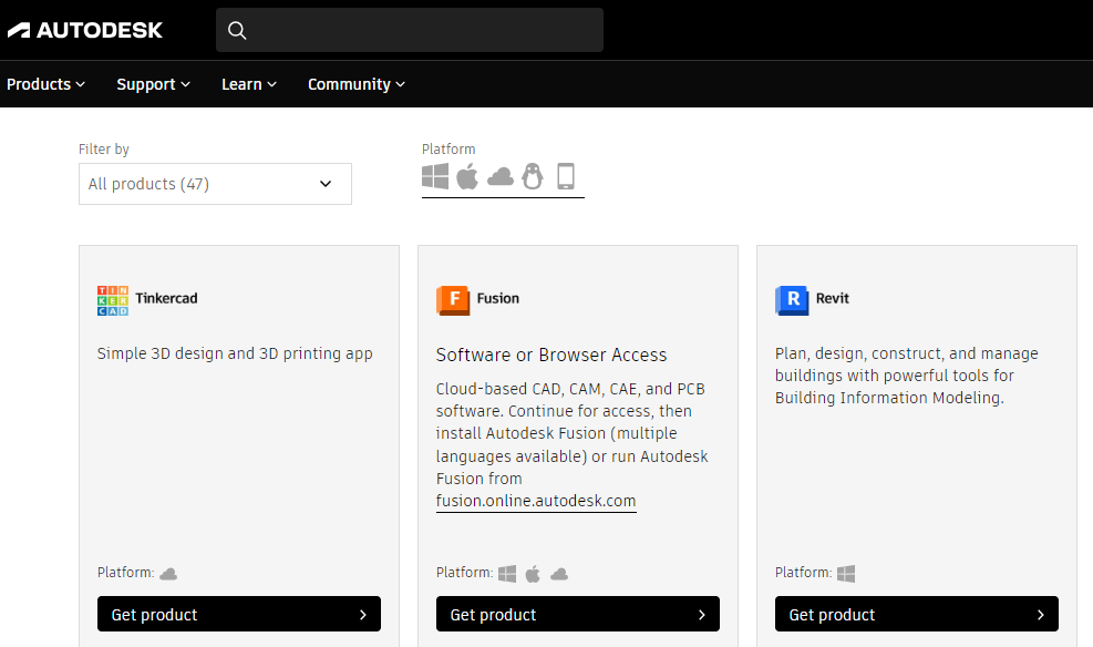
To start learning fusion 360 here is a link for the videos that helped me to develop my skills in 3-d Fusion 360 tutorial.
Design Process
Step 1: Setting Up the Fusion 360 Workspace
- Open Fusion 360 and create a new project.
- Set up the units (millimeters are recommended for this project).
- Import or draw the 2020 aluminum profile as the base structure.
Step 2: Designing the Velcro Strap Holder
- Create a sketch on the appropriate plane where the Velcro strap will be mounted.
- Design a rectangular cutout or slot that fits the Velcro strap width.
- Add fillets to the edges for smoothness and comfort.
- Extrude the sketch to create a 3D part that can be attached to the aluminum profile.