Final project
Agriculture and technology in Peru, Seed ready
Something I'm not sure about was the Applications and Implications questions, thanks to Epifanio who told me that I should answer them from the point of view of the completed project. Remember it!!!
- What did you design?
- What materials and components were used?
- Where did they come from?
- What parts and systems were made?
- What processes were used?
- What questions were answered?
- What worked? What didn’t?
- What are the implications?
- How was it evaluated?
Ready to see my final development process?
It was quite a challenge, I am very happy with what was achieved and I love the idea of continuing with the research and future versions of this project.
My documentation is developed in a spiral, each process from the smallest and simplest was a great advance, this spiral method will help you to be able to finish your project and therefore the Academy, it can be somewhat tedious but at the same time it will be rewarding when you do it. you finish. Each process I developed was important to complete my final project, it works in parallel and in a spiral to reach the objective.




What did you design?
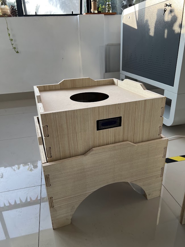
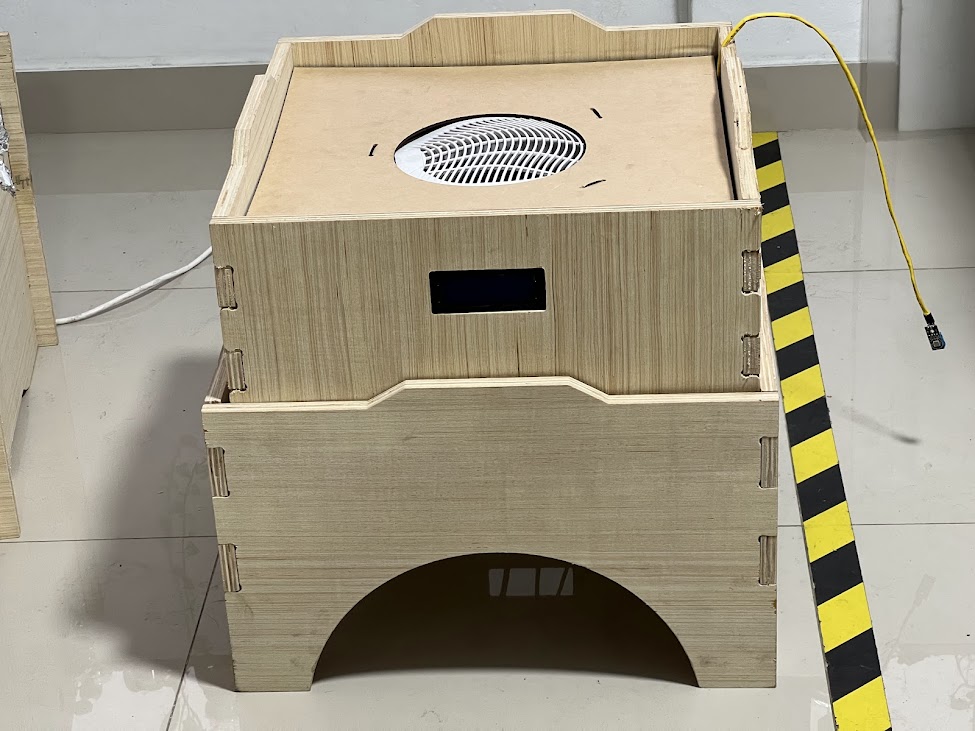
I designed a modular fruit and seed dryer with temperature and humidity control.
What materials and components were used?
- Board Microcontroller ESP32 c3
- DTH11 Temperature and Humidity Sensor
- nichrome wire
- Fan
- Recycled MDF
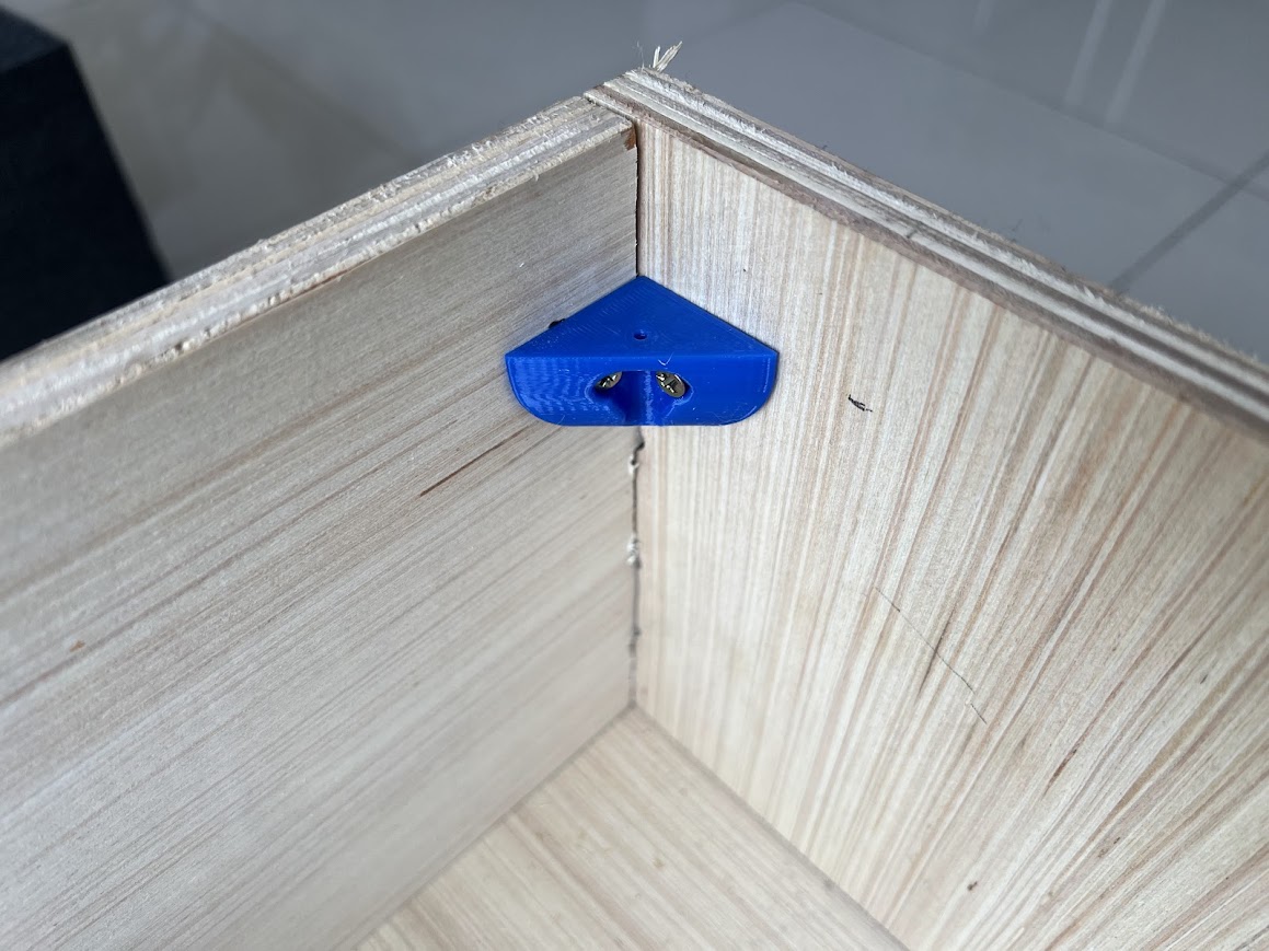
- 3D printed supports
- Pressed tripley
Where did they come from?
The components were purchased from local suppliers (PARURO) The microcontroller was sent to us by Vannesa from the US since they don't sell them in Peru. The MDF was recycled from some cuts that had been made in the Garage Lab laboratory, as was the heater, which was also recycled to use the nicron wire and the fan. I bought the pressing tipley at a local store called Martin, which was close to the Fab Lab of the Scientific University where I routed the module.
How much did they cost?
Components
| Name | Description | Units | Price |
|---|---|---|---|
| Temperature sensor | The DHT11 is a low-cost, easy-to-use digital temperature and relative humidity sensor. | 1 | 5 $ |
| LCD | I2C Liquid Crystal Displays. | 1 | 8 $ |
| Fun | Cooler Fan | 1 | 5 $ |
| Resistor | Nichrome Wire Electrical Resistors | 1 | 20 $ |
| Xiao | Seeed Studio XIAO ESP32C3 | 1 | 15 $ |
| Relay module | A relay is an electrically operated switch | 1 | 3 $ |
| 53 $ | |||
Materials
| Name | Description | unit | Price |
|---|---|---|---|
| Plywood | Triplay Capinuri D/D Trimasa 1.22 X 2.44 12 Mm | 1 | 30 $ |
| PETG 1Kg | PETG filament roll for 3D printing with a diameter of 1.75mm. | 1 | 10 $ |
| Glass | Glass thickness 10 mm | 1 | 5 $ |
| Baking sheet | Full aluminum baking tray 66cm x 46cm | 1 | 5 $ |
| Keke mold | English Cake Mold 31X11.5X7Cm | 2 | 10 $ |
| 60 $ | |||
Total
| Name | Price |
|---|---|
| Components | 53 $ |
| Materials | 60 $ |
| 113 $ |
What parts and systems were made?
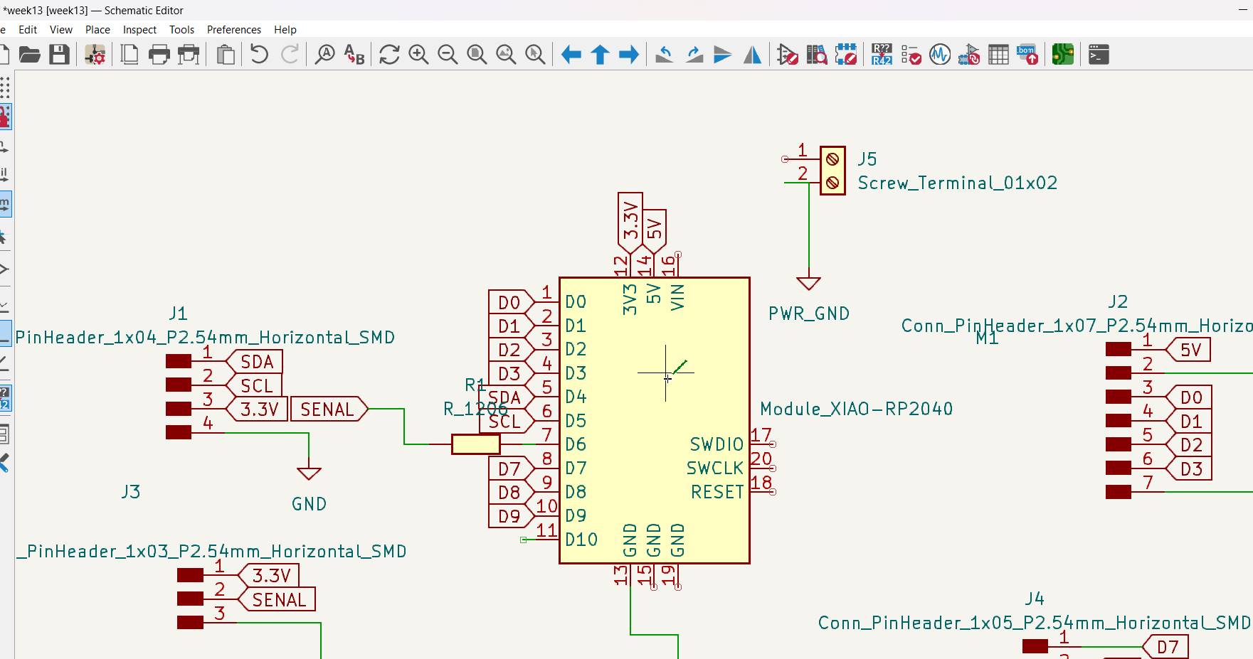
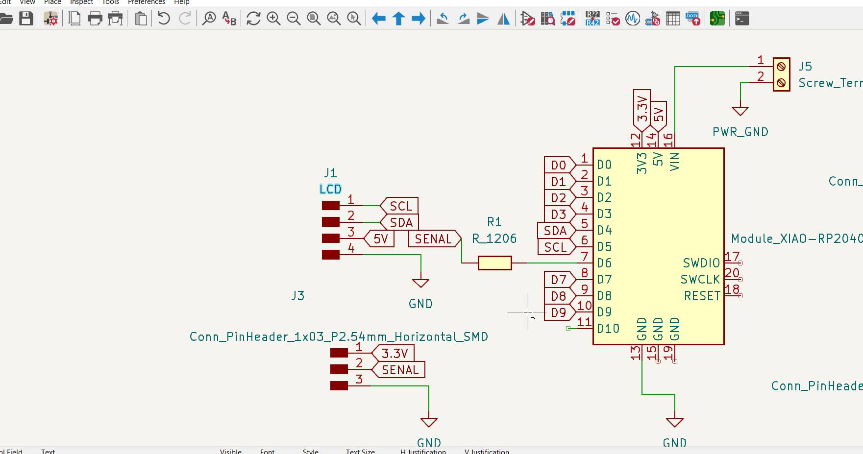
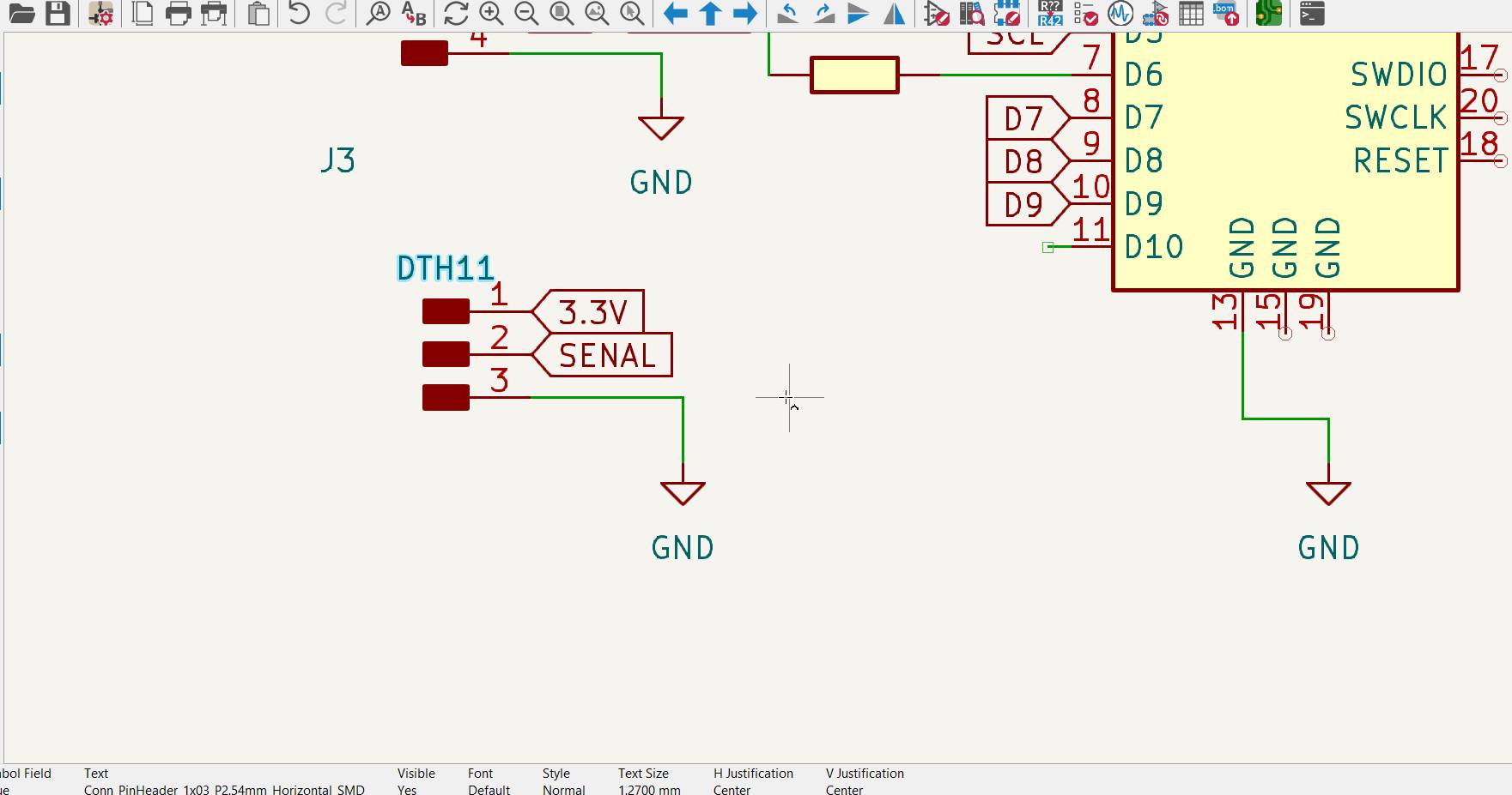
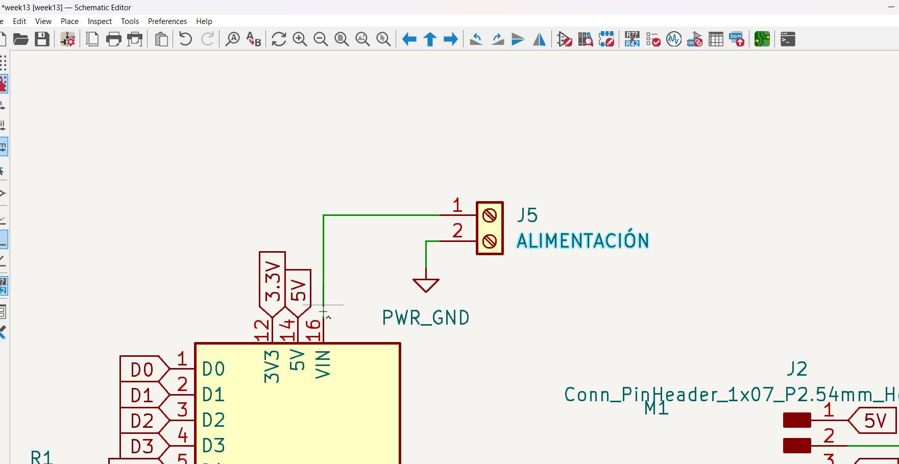
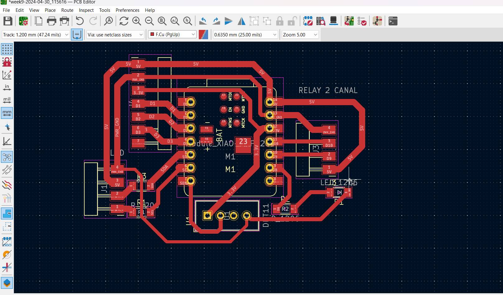
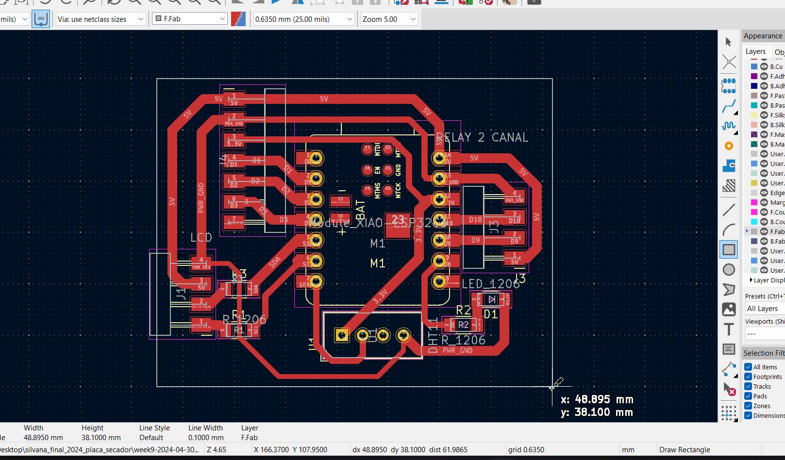
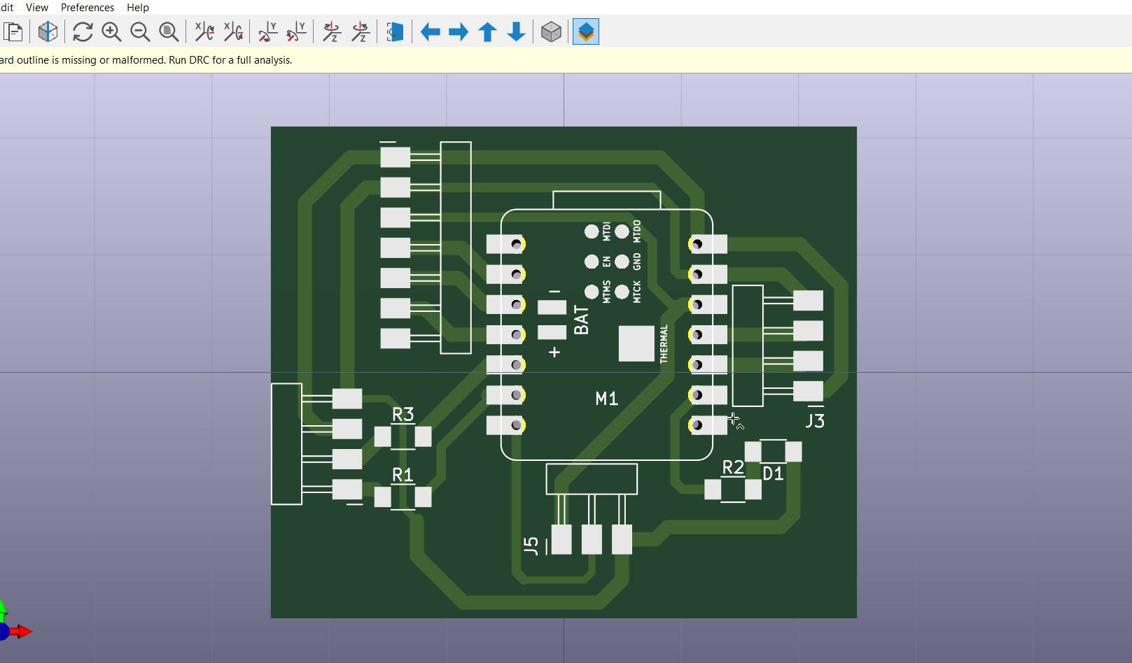
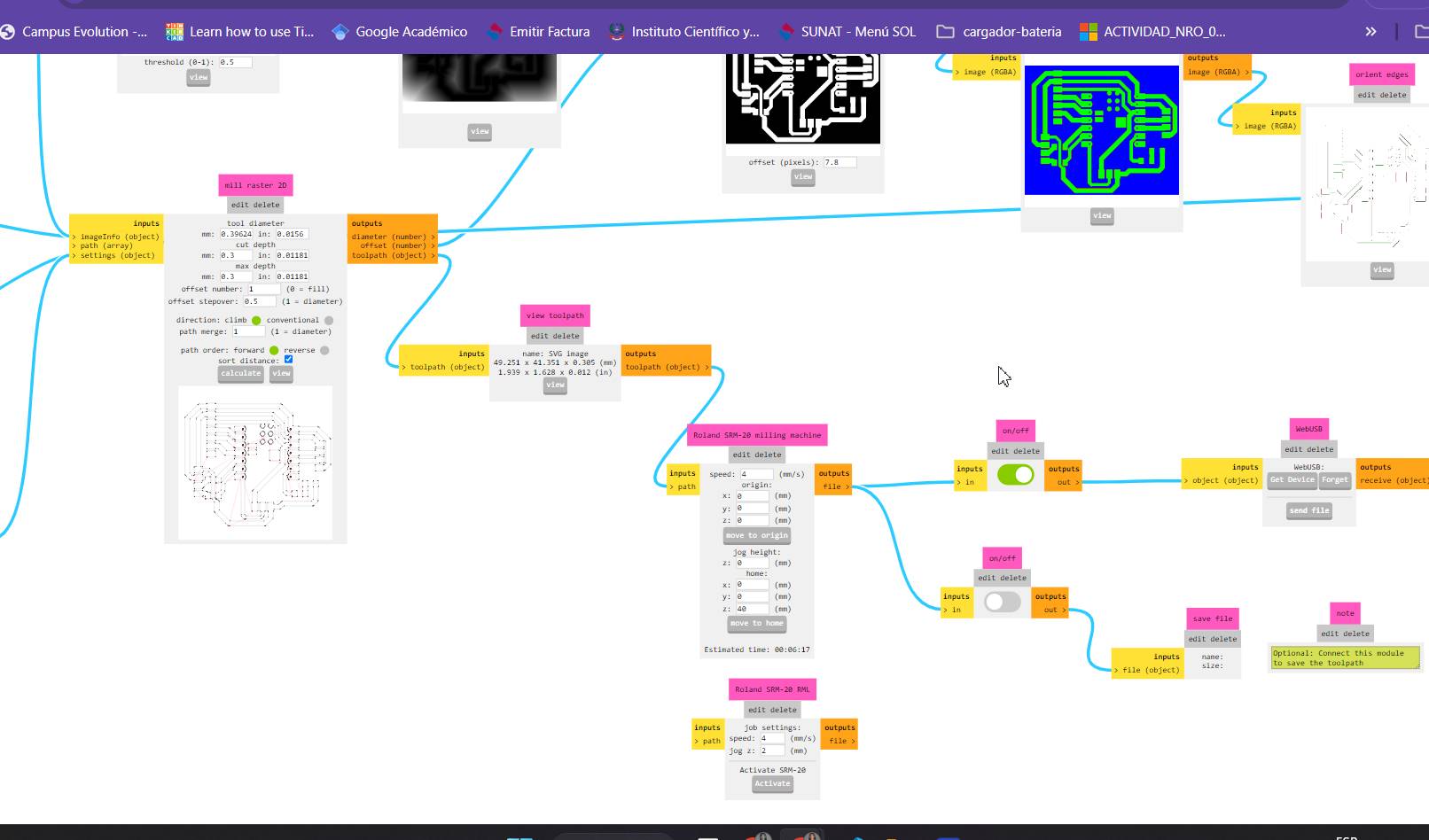
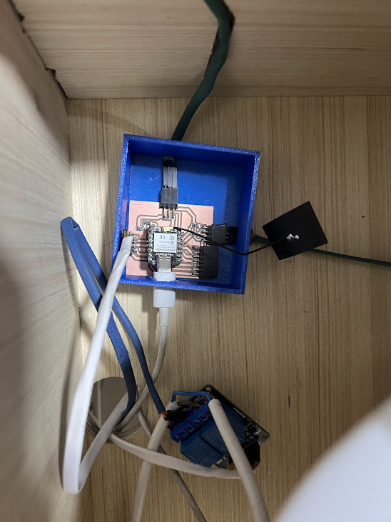
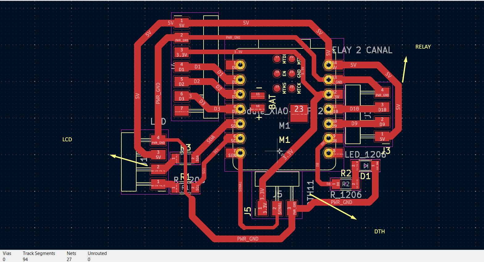
- The board was manufactured, you can see it in week 13.
- Design and manufacture the nestable module as you can see in week 16
- I design the case for the plate and the supports for the division and the video on the top
- Create the schedule with the help of gpt chat week 08
What processes were used?
- 3D design and printing
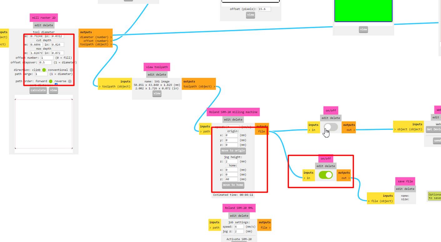
- PCB design and milling
- Laser cutting
- Programming
- CNC machine
What questions were answered?
- Can the system effectively maintain and control the temperature and humidity inside the dryer?
- Is modular design viable for dryer assembly and operation?
Answer: Yes, the system was able to maintain the desired temperature of 45°C and adjust the ventilation and heating accordingly, ensuring an optimal environment for drying fruits and seeds.
Answer: Yes, the modular design proved to be viable, allowing for easy integration and adjustment of components, as well as flexibility for future system enhancements and expansions to grow vertically.
What worked? What didn’t?
Heat generation works and the sensor that detects the temperature and humidity of the module works as programmed to turn the fan and heater on and off. Problems such as the glass part were resolved to be able to place and remove more carefully, I could improve that part of the glass lid that I see is not working as I would like. I could design some handles in my next versions to more easily remove the glass
How was it evaluated?
For the evaluation and functionality I had my instructors who verified the operation of the dryer, I also dried various fruits to see the results, seeing that the thinner the fruit the sooner it dries, normally it takes 5 hours to dry to 7 hours depending on the thickness during that time I was testing according to functionality tests for temperature and humidity control, I had my colleagues at the Fab Academy test the result of the dried fruit, in a Teachers' meeting I also explained and showed them and made them try the final product that my dryer achieves.
What are the implications?
Next steps include adding a timer for the duration of operation and exploring alternative heating materials. During the research for the development of this project, I considered other materials to develop this module, but did not choose options such as industrial heat resistors due to the price. I want to add a timer to program the drying time and improve the structure of the box, perhaps with another type of fit between the pieces.
This modular dryer can improve the efficiency of drying fruits and seeds, reducing losses and improving the quality of the final product.
The modularity of the design allows for easy adjustments and expansions, making it easy to adapt the dryer to different volumes and types of agricultural products, for drying seeds
Incorporate solar panels to power the system, making it more sustainable and reducing dependence on non-renewable energy sources.
Project Development
Checklist
- Principles and practices
- Project management
- Computer aider design
- computer controlled cutting
- 3D scanning and printing
- Electronic design
- Computer controlled machining
- Embedded programming
- Output devices
- Mechanical design y machine design
Week 01. Sketch
As the course progressed, some ideas and improvements arrived for my final project, one of those ideas was about form and structure, while I was making each assignment, I found a way to make my project idea a reality, it all started with the sketch , and the first week was PRINCIPLES AND PRACTICES
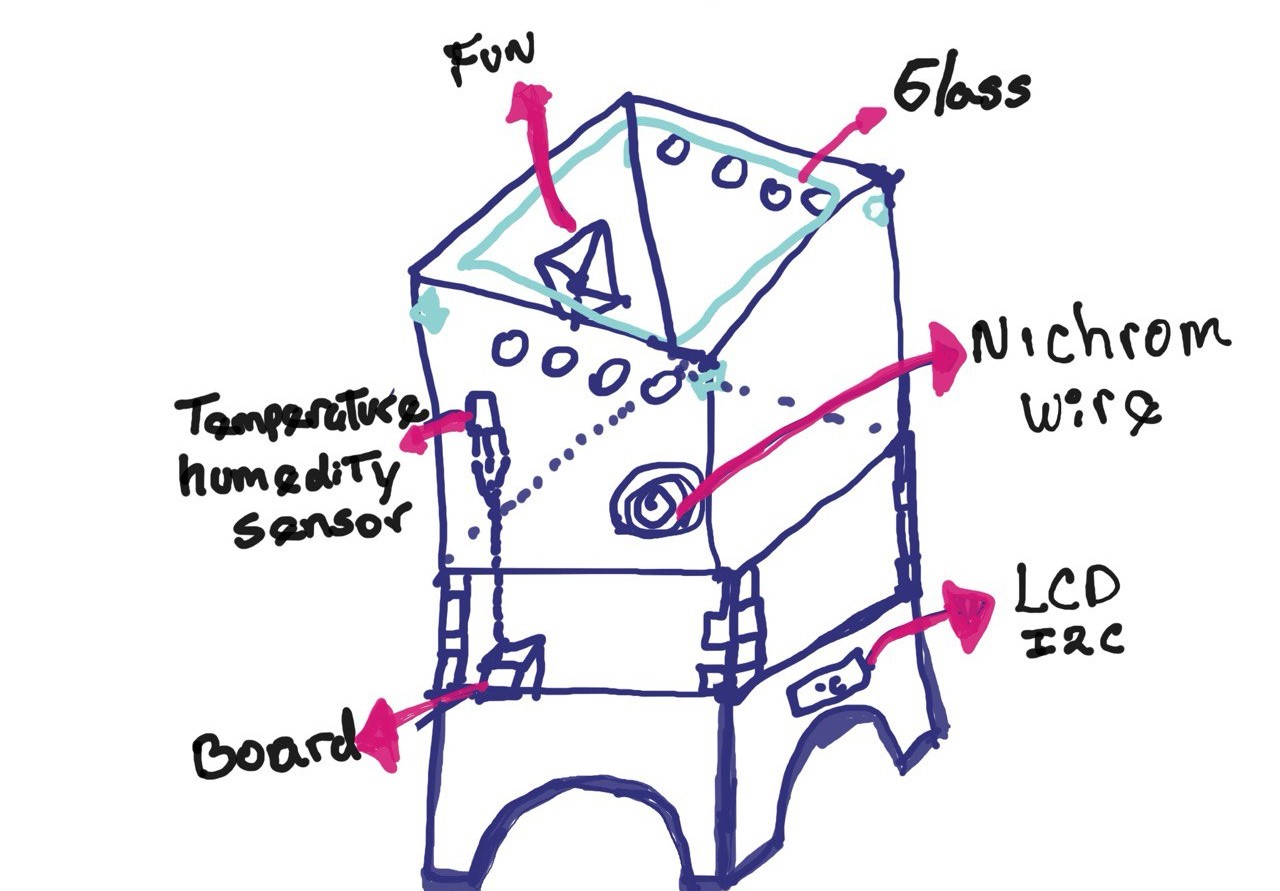
My final idea is to build a modular fruit and seed dryer, where you can see the temperature and humidity of the box, the heat will be generated from a heater that is made up of nichrome wire.I explain it in more detail here.
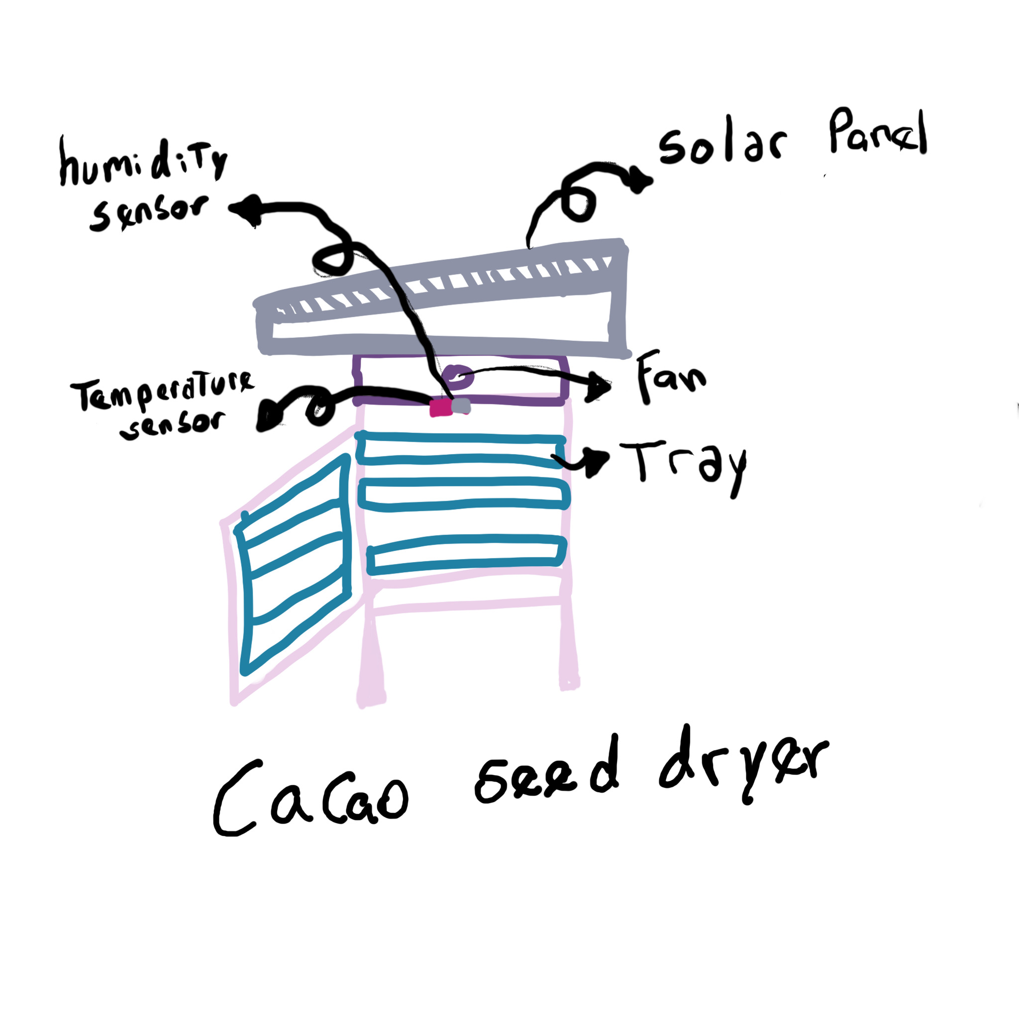
Here I detail how I will do it, first I will design my board, then I will make my modular box, this part was very interesting since I had some mistakes but I learned, and I will write them down so that you who read this documentation do not make them.
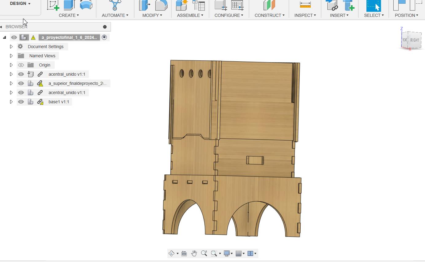
Here I made my design in fusion of my second version, everything turned out well, I loved the result.
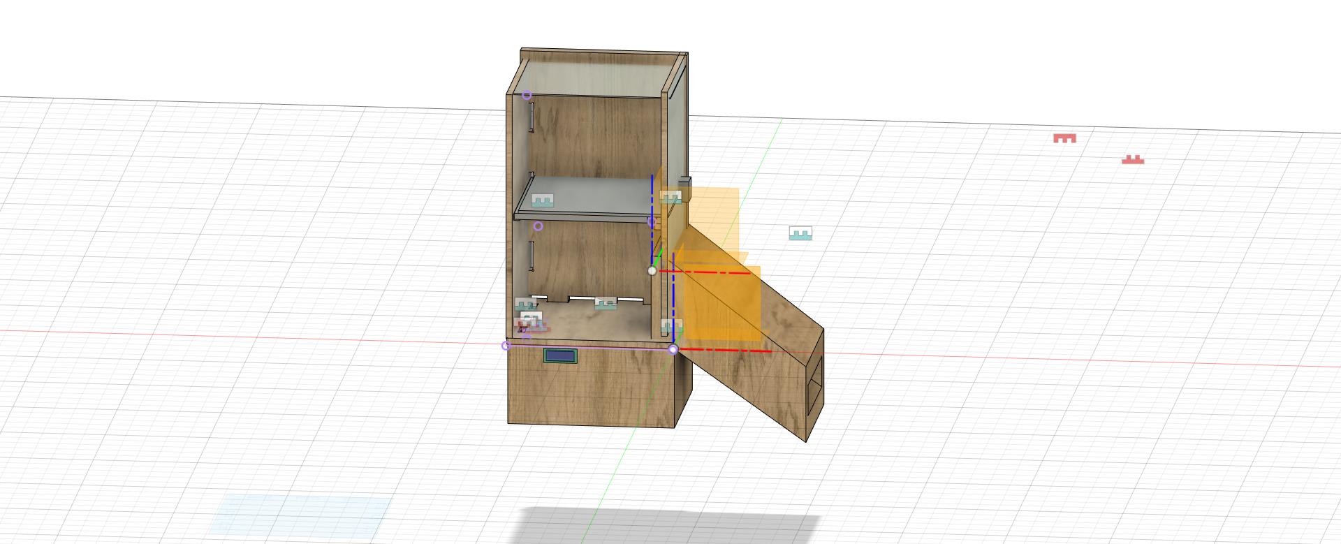
My initial idea was inspired by homemade dryers that some farmers make to dry their group with the direct sun, there were varied and very interesting designs.
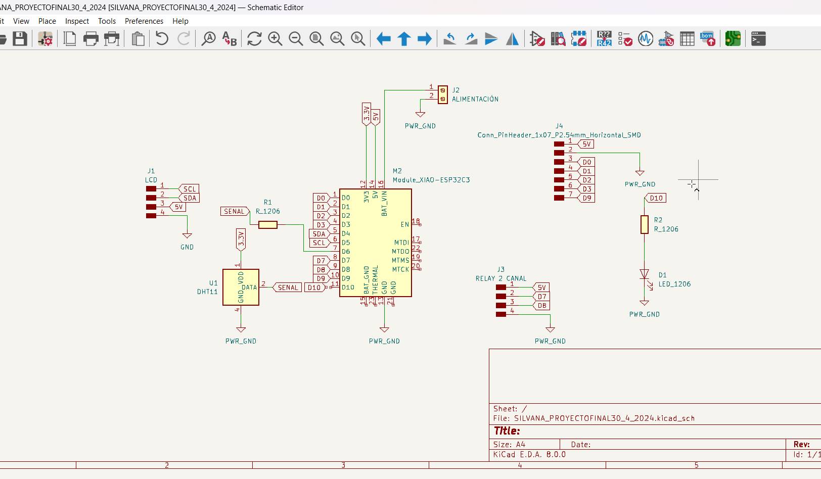
To design my modular temperature control system, I first developed the electronic board, selecting components such as the dth11 temperature sensor, a microcontroller, and a relay to control the heat resistance and the fan. I did the circuit and PCB design using software like KiCad. Then, I designed a modular box that can be nested in three parts: the control module that includes the microcontroller, sensor and relay; the power module with the power source; and the heating/ventilation module with the heat resistance and the fan. I used 3D design software such as Fusion 360 to create the models, and adjusted the 3D printed prototypes to ensure a precise fit and adequate ventilation. During the process, I encountered several problems: the parts of the box did not fit together correctly, which I fixed by adjusting the tolerances in the design; and the ventilation was insufficient, which I solved by adding more ventilation slots. For programming, I configured the microcontroller to read the data from the temperature sensor and activate the relay when the temperature was below 45°C, turning it off when this temperature was reached. I documented all errors and fixes to learn and improve the design, and to provide useful guidance to others working on similar projects.
Project Management
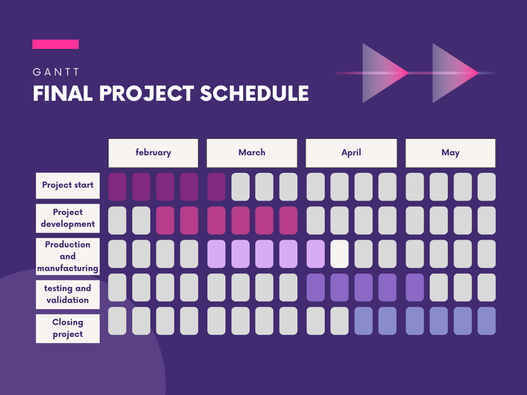
To organize myself better, I tried to schedule my 45 hours of work per week with the Academy, something important here is that my boss Percys gave me the facility to be able to use the Toulouse Lautrec CRESTISPACE Laboratory to be able to advance some tasks that were assigned to me at the Academy, Thanks to that support I was able to better organize my calendar and make my gantt as realistic as possible. Always taking into account spiral and parallel work, to achieve weekly tasks and advance at the same time as the final project.
Week 02. Computer aider design
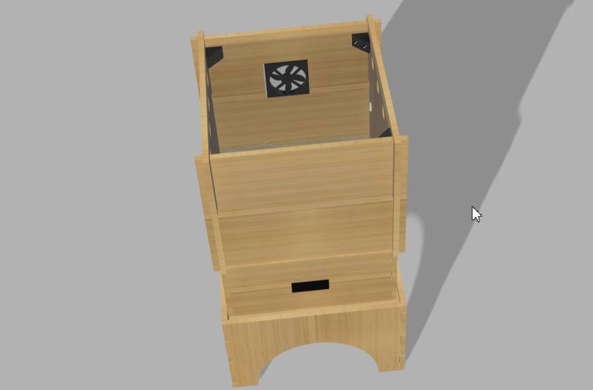
Here I show you my first design and my second design, there is a difference since it was before I did my week 7 Computer-Controlled Machining where I understood about CNC Machine and insert design.
Design 2
As you can see in my exploration of design programs, I really liked modeling in Fusion 360 and that is why I decided to model my final project prototype here.
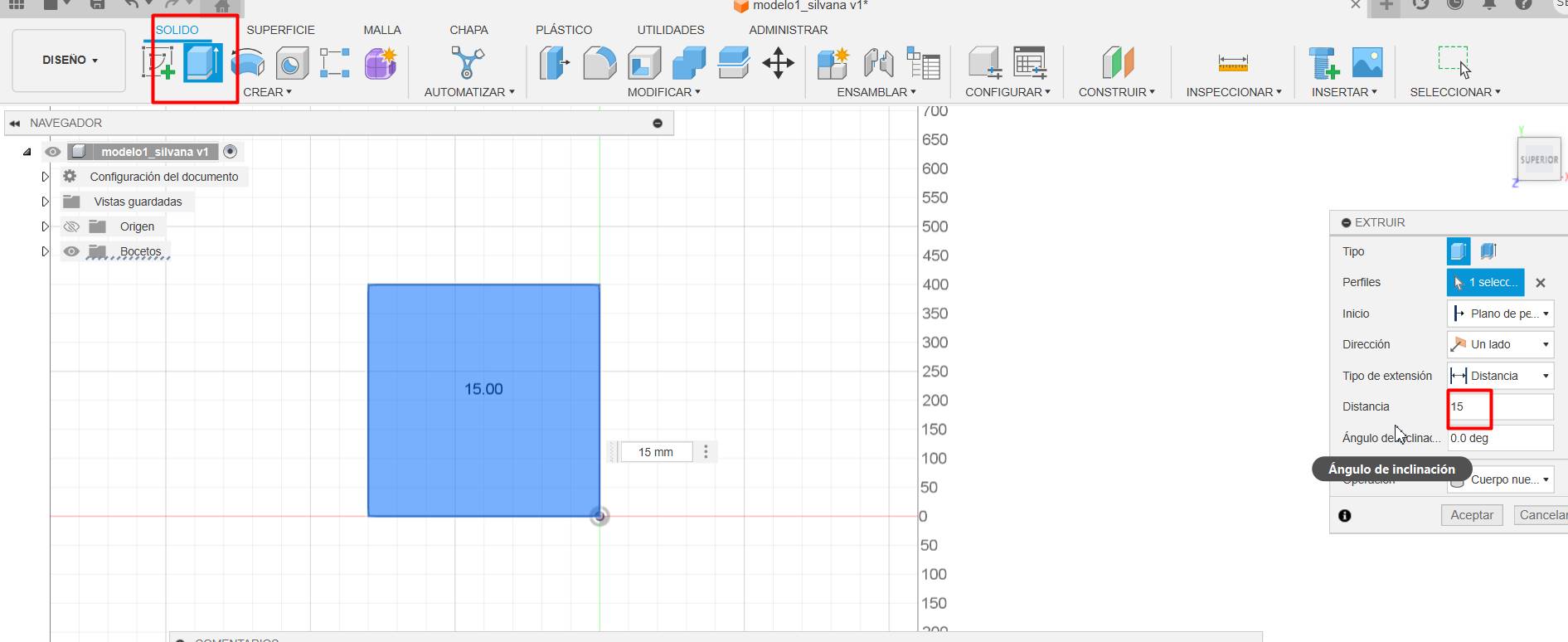
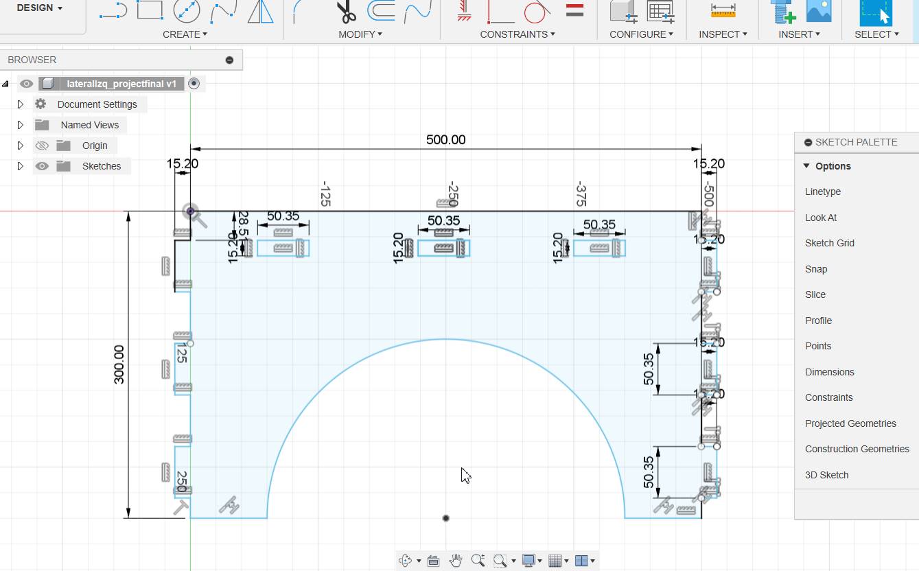
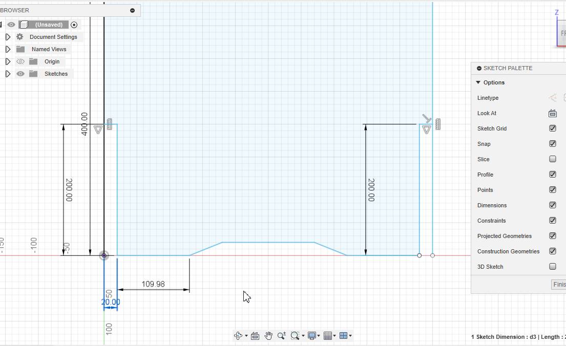
I started with a square measuring 400mmx400mm
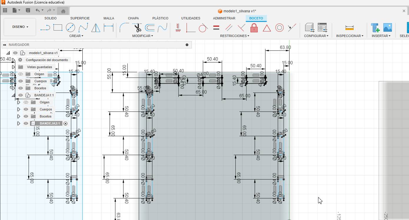
Since I wanted to know the measurements of everything, I started to limit everything and take the measurements of each part. Since I'm still trying to master this program, it might look strange.
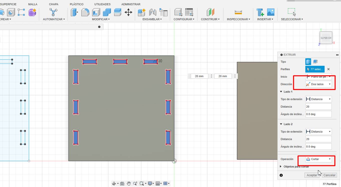
Here I started making the holes to fit my seed dryer easier.
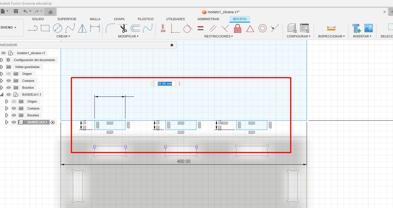
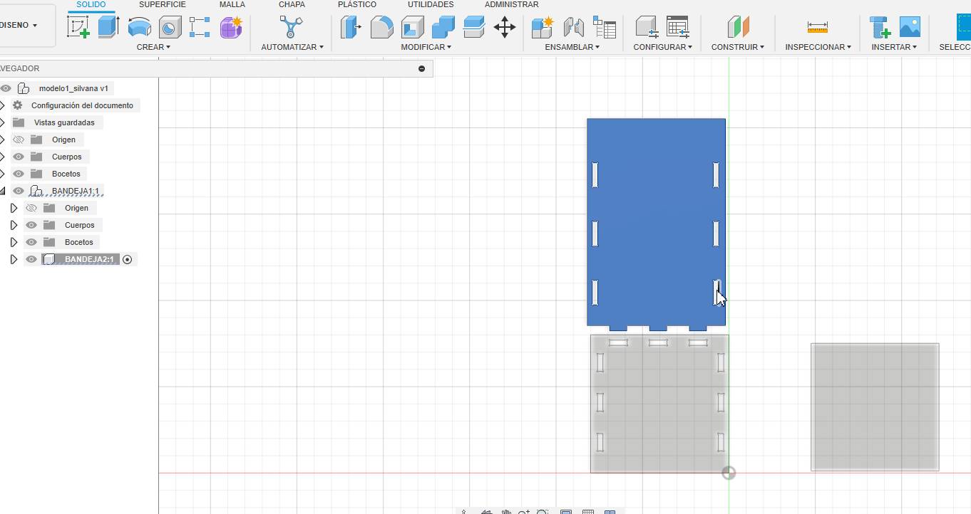
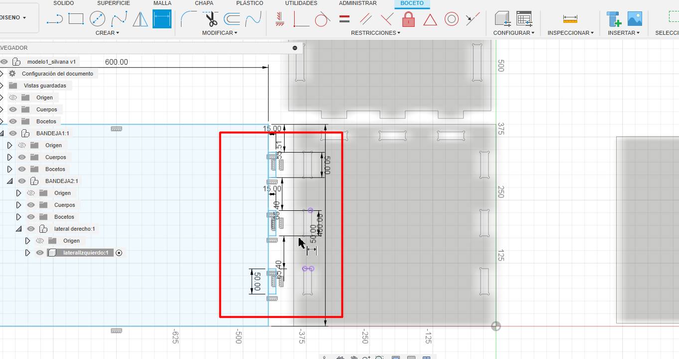
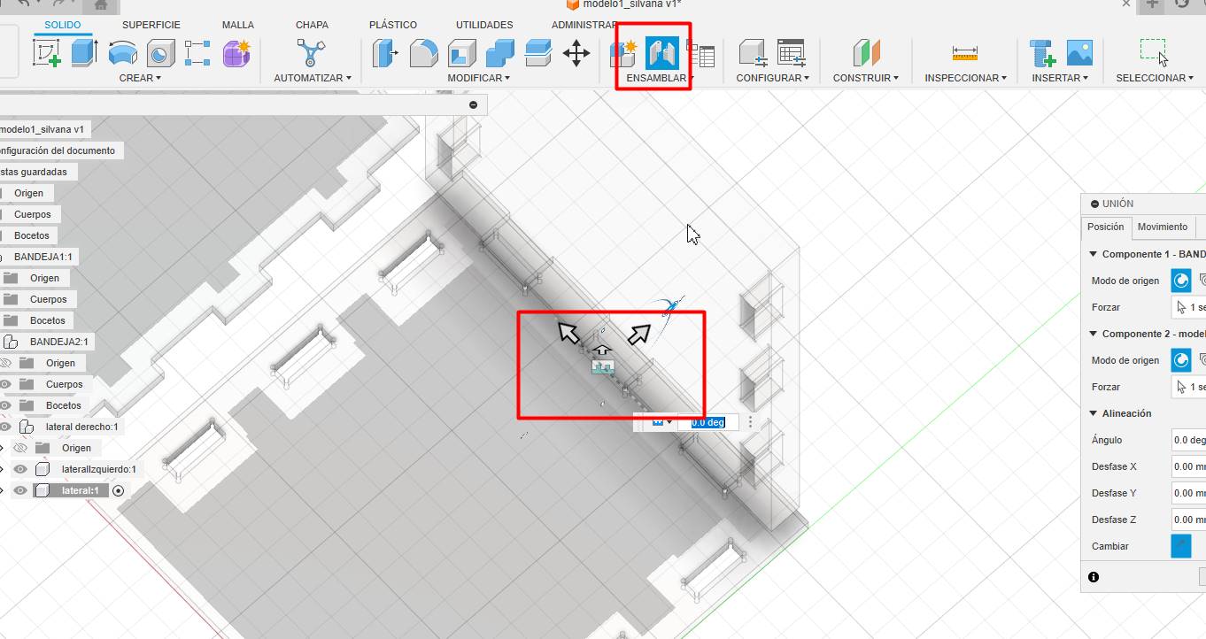
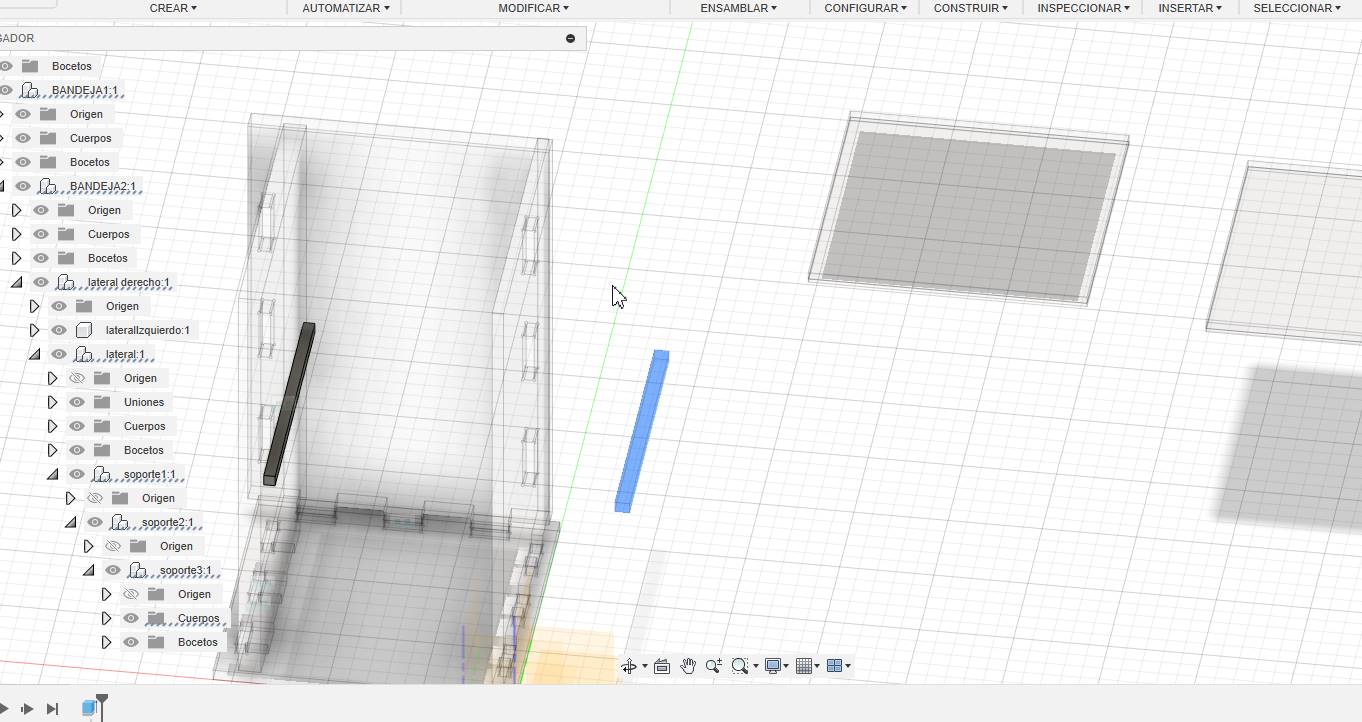
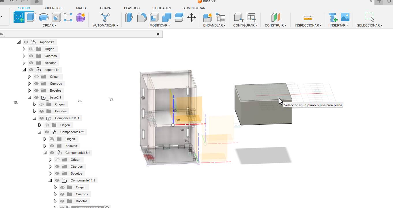
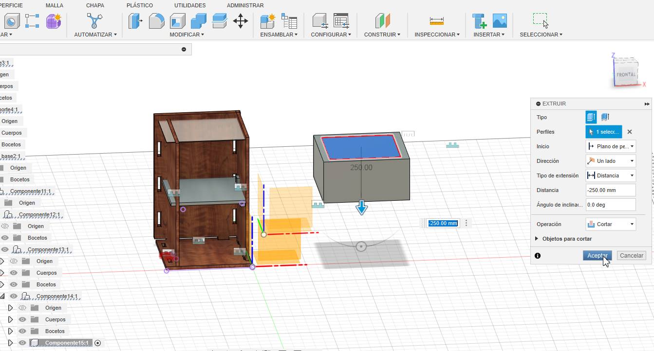
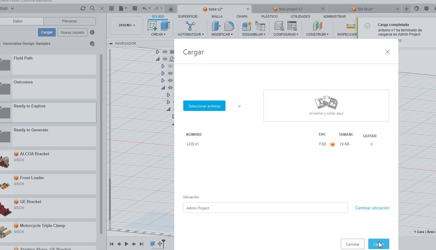
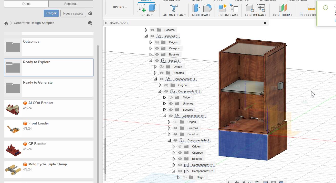
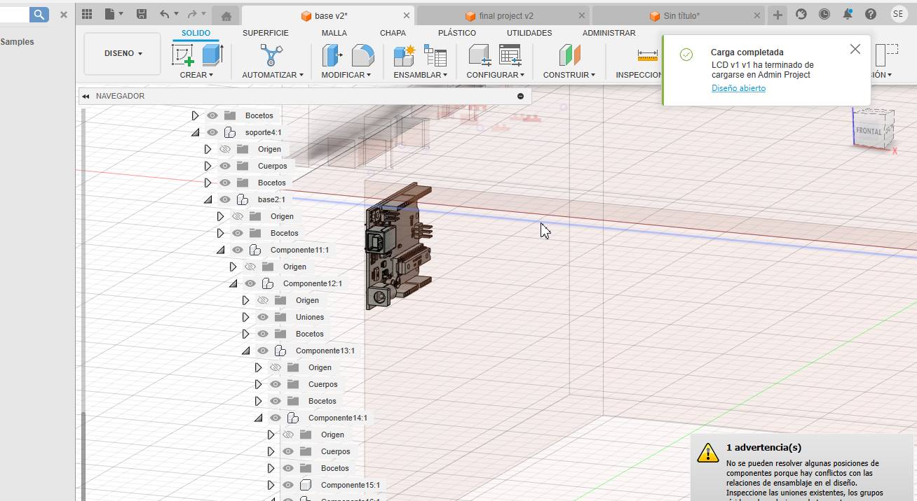
Rotate the arduino to place it on the left side
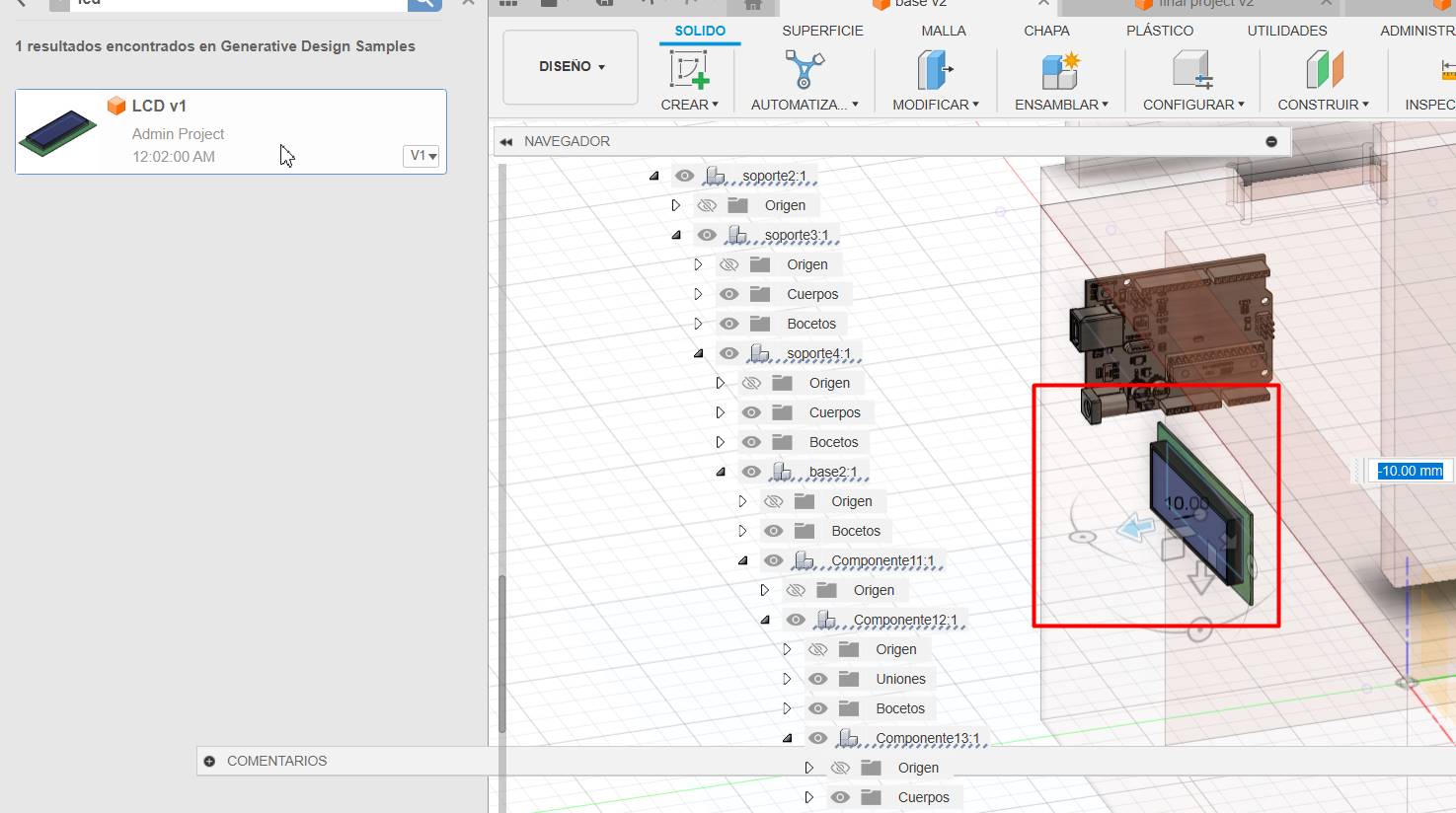
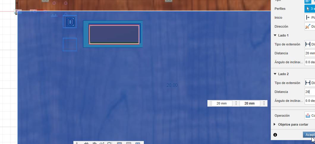
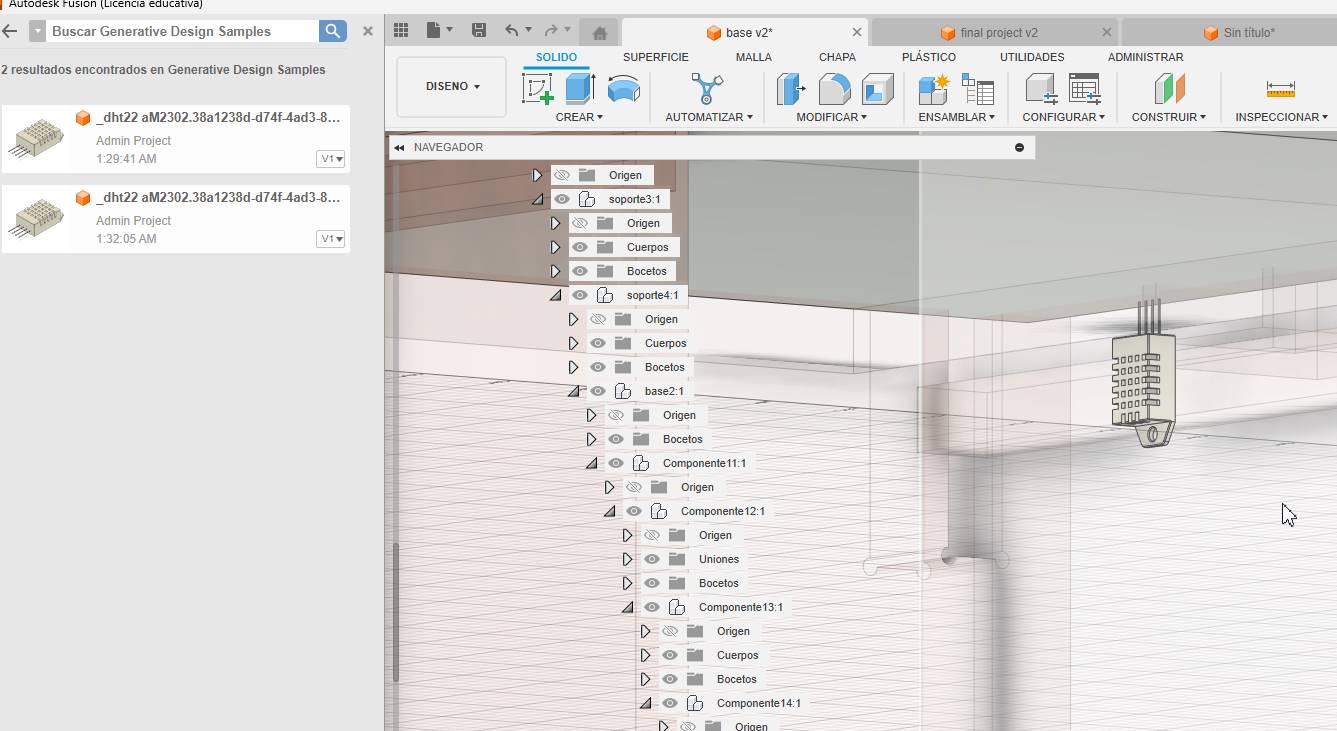
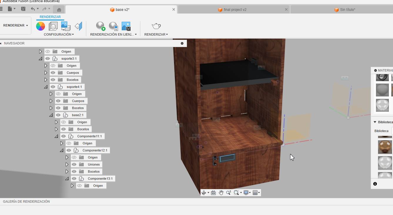
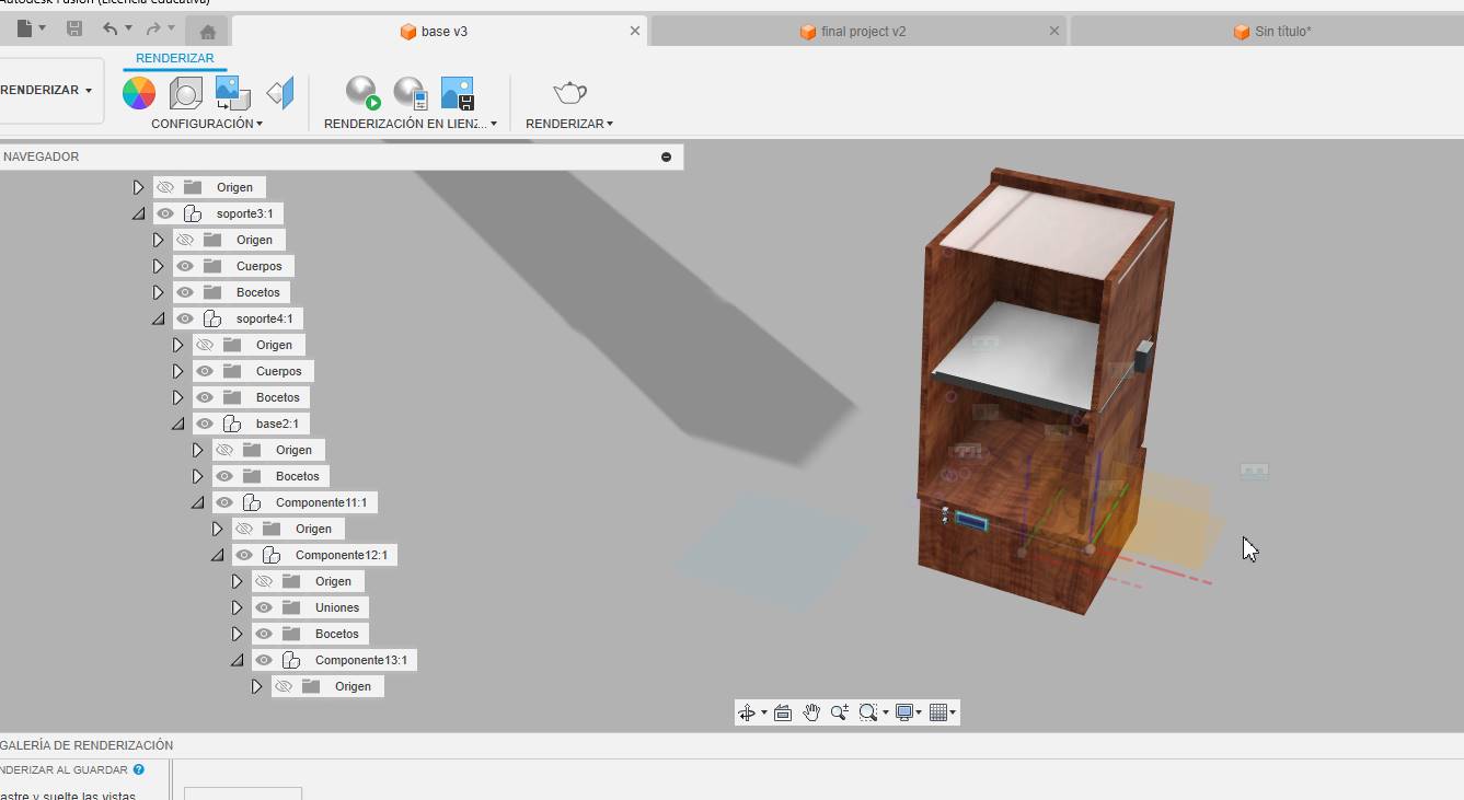
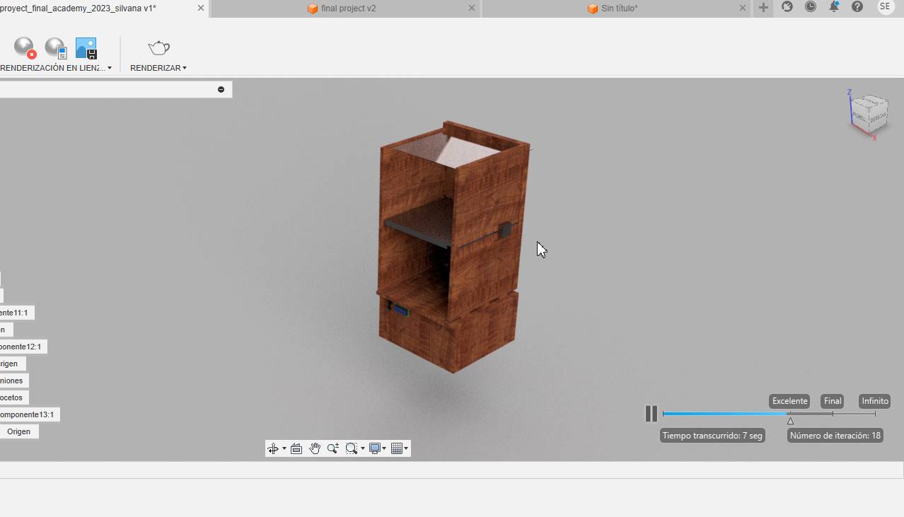
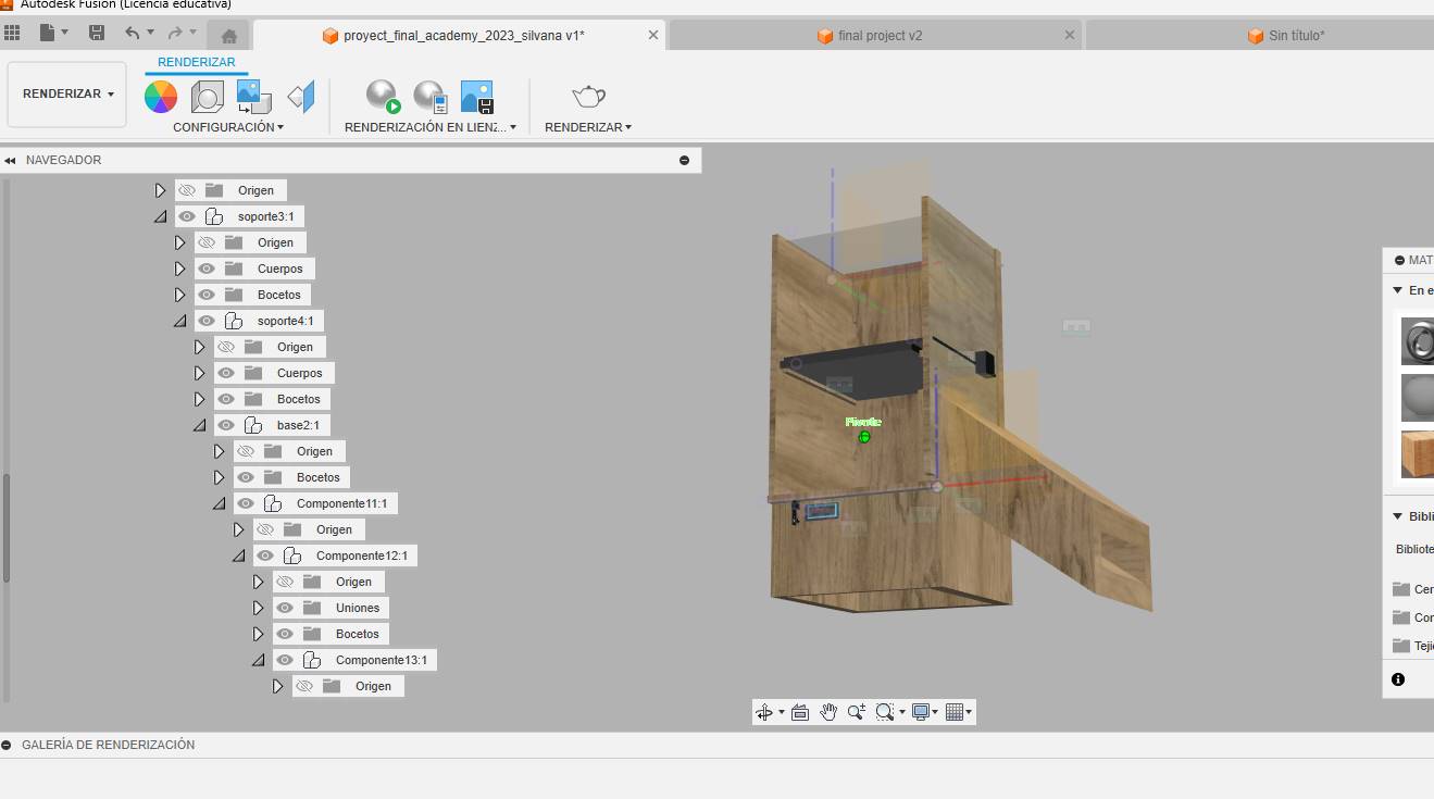


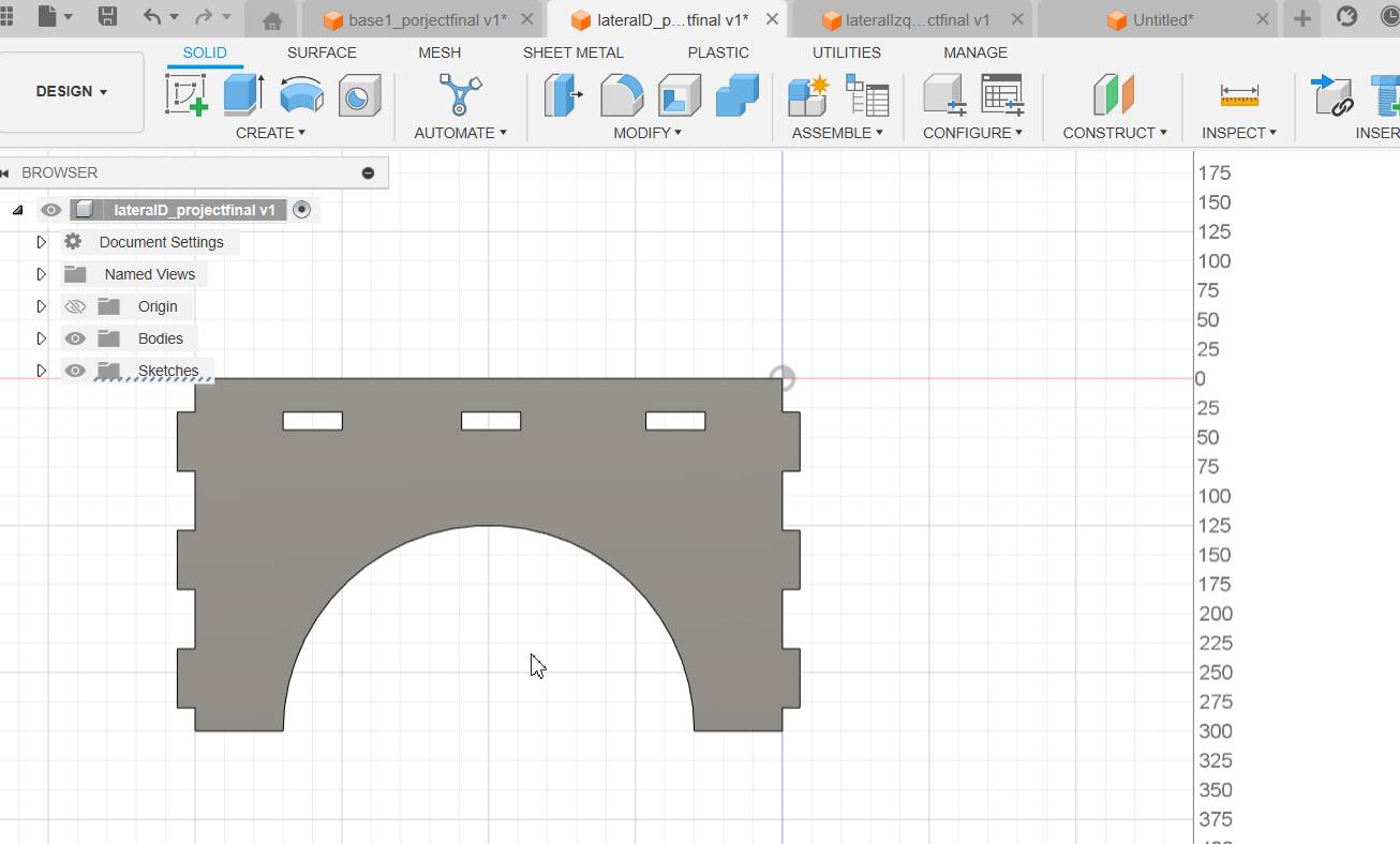
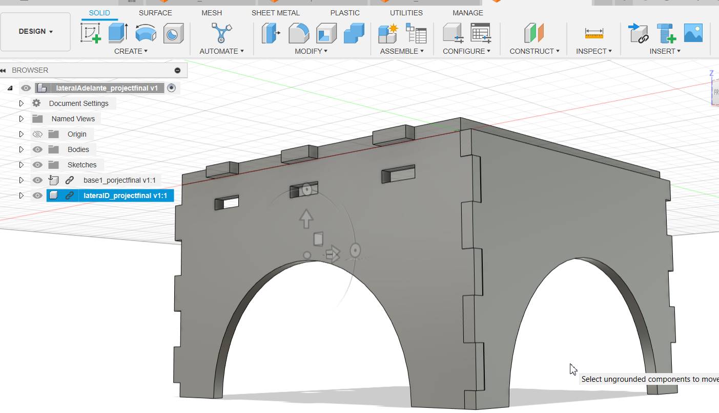
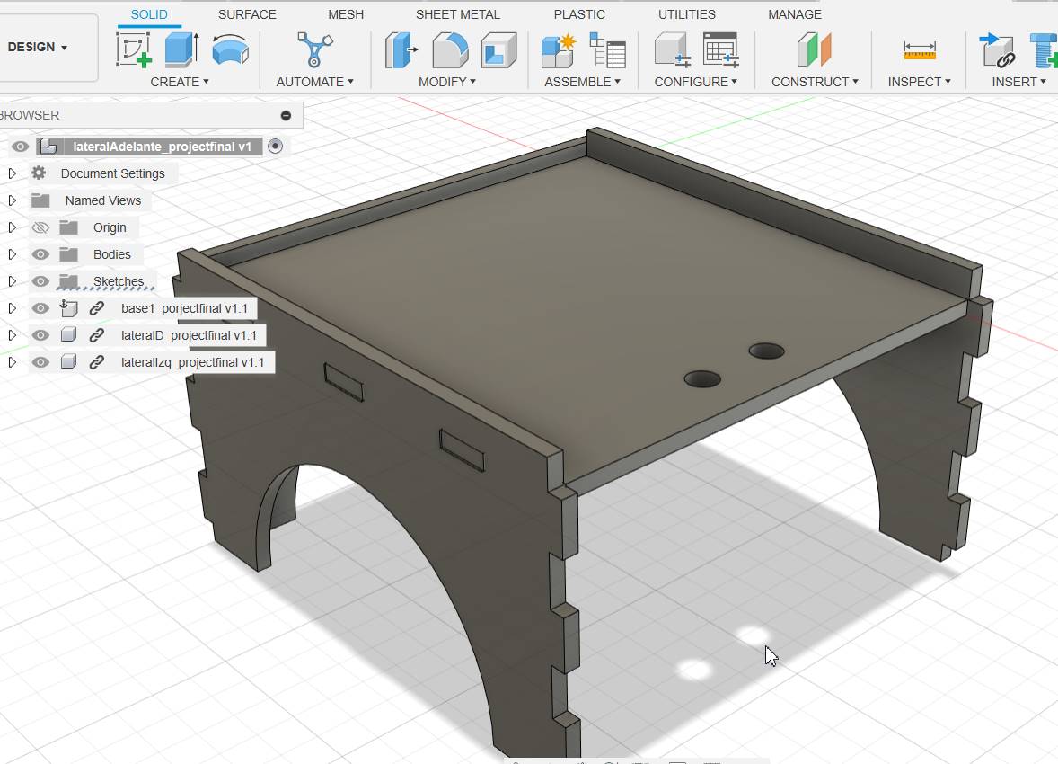

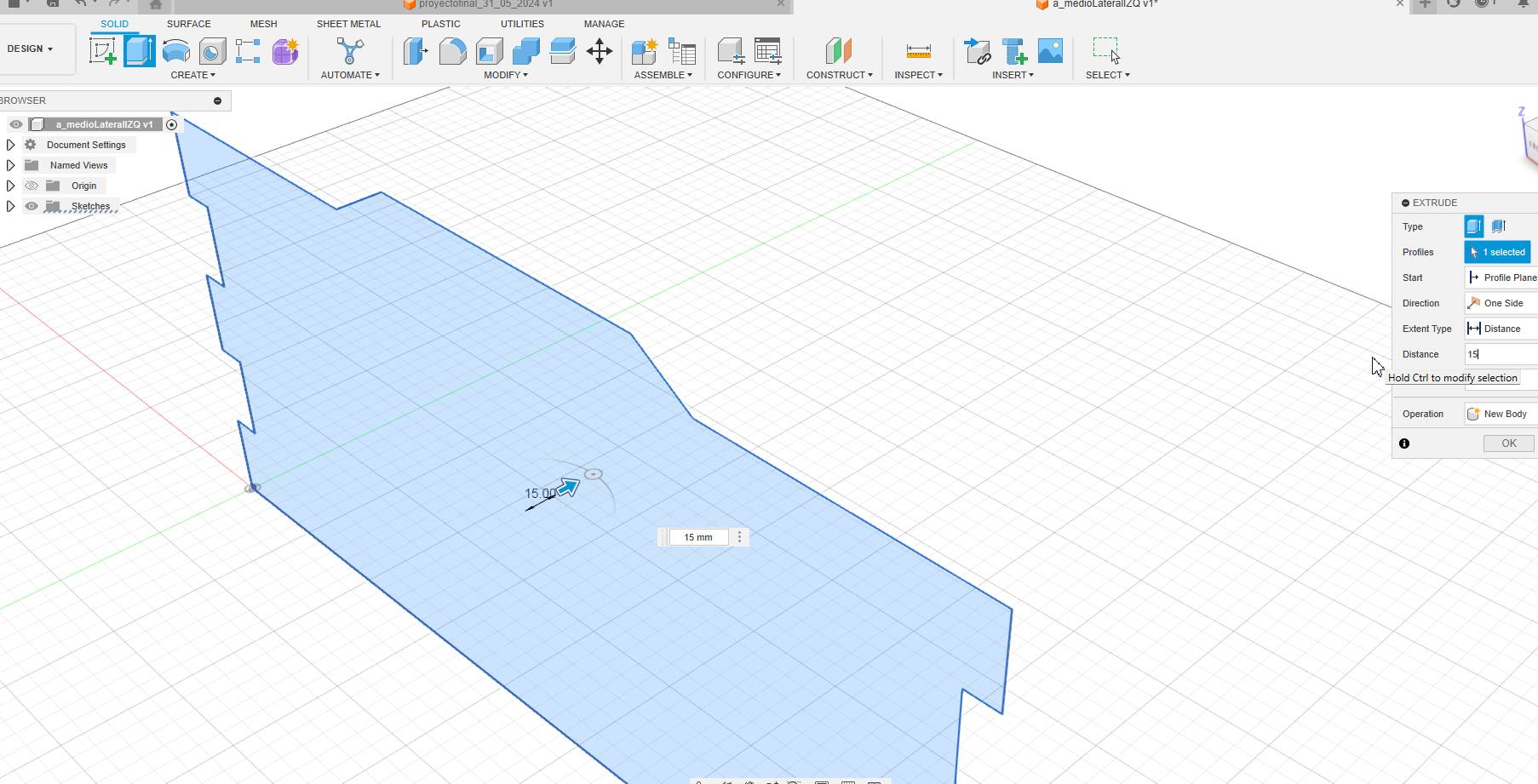
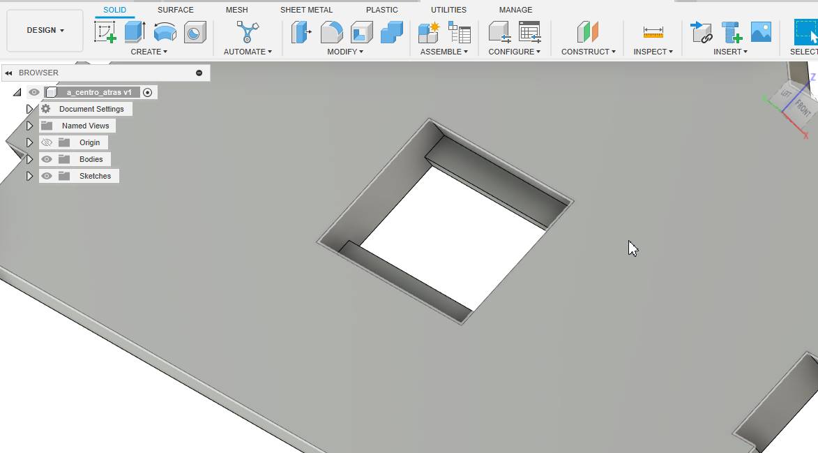
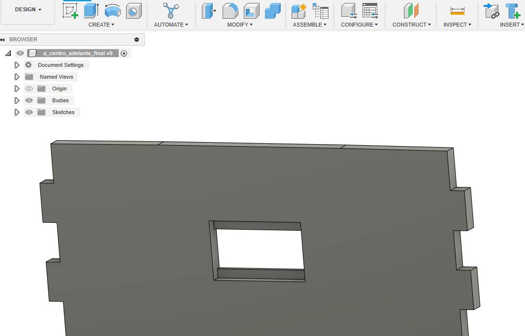
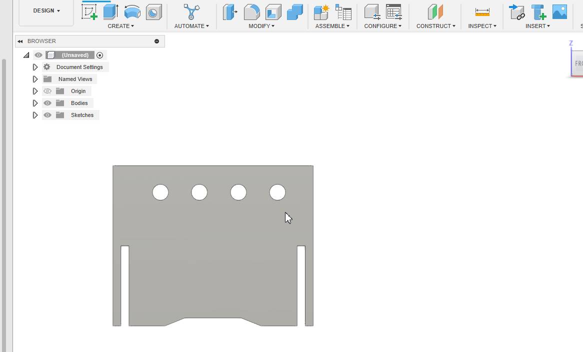
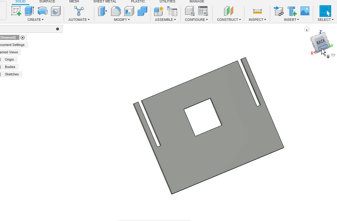


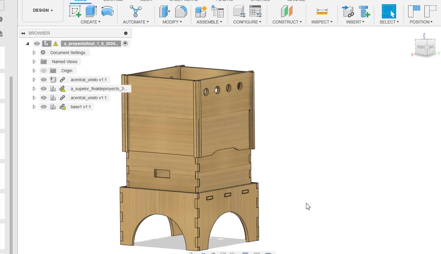
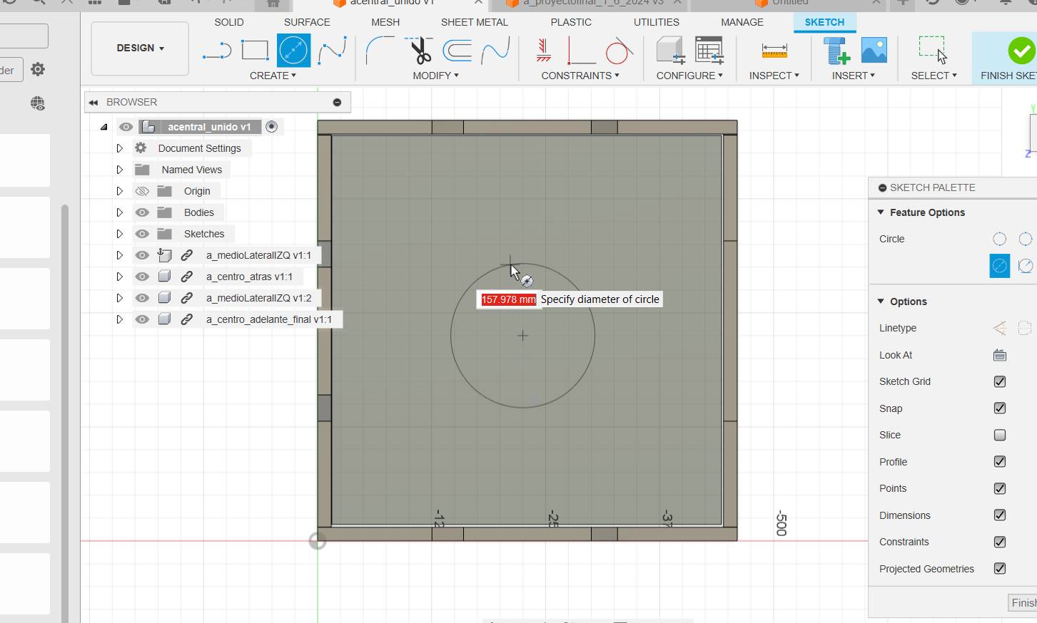
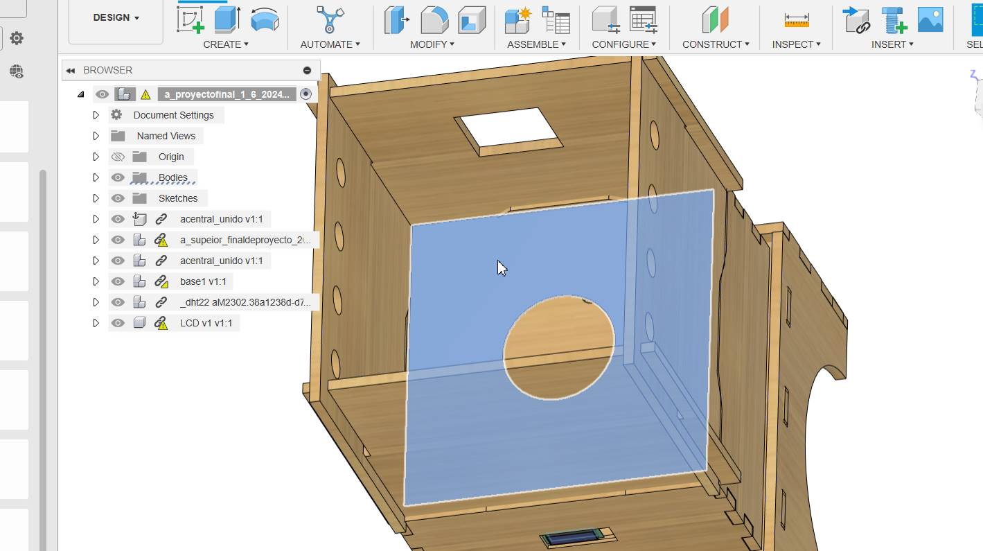
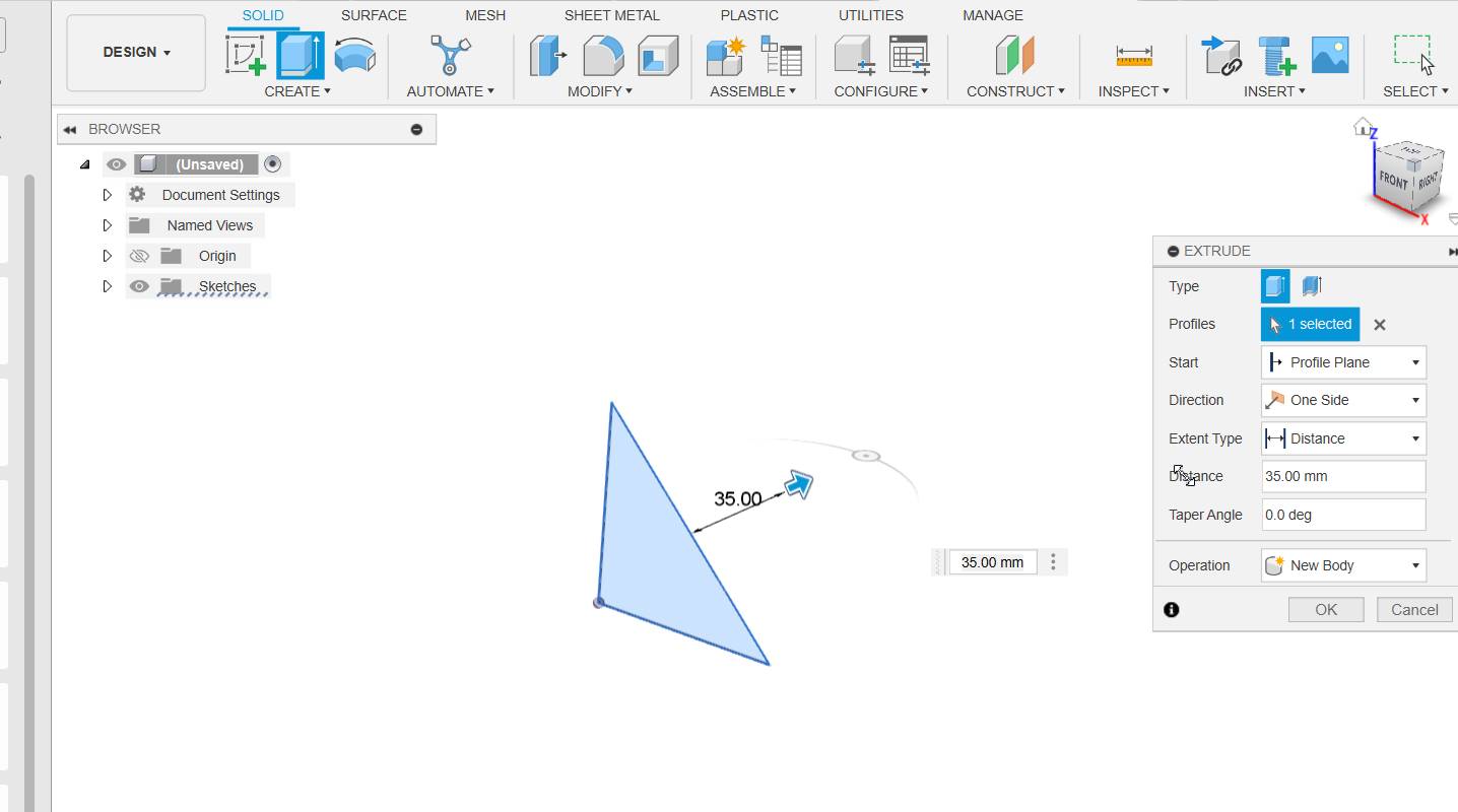
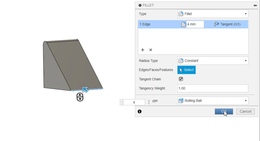
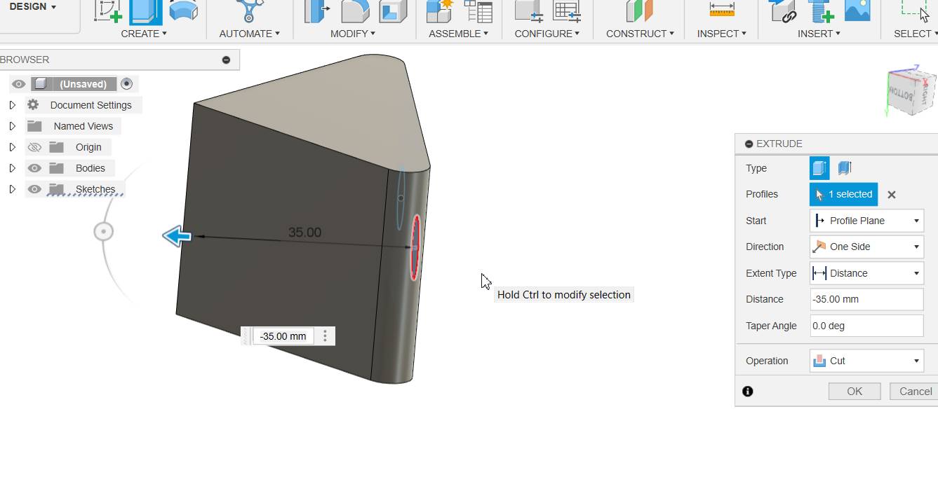
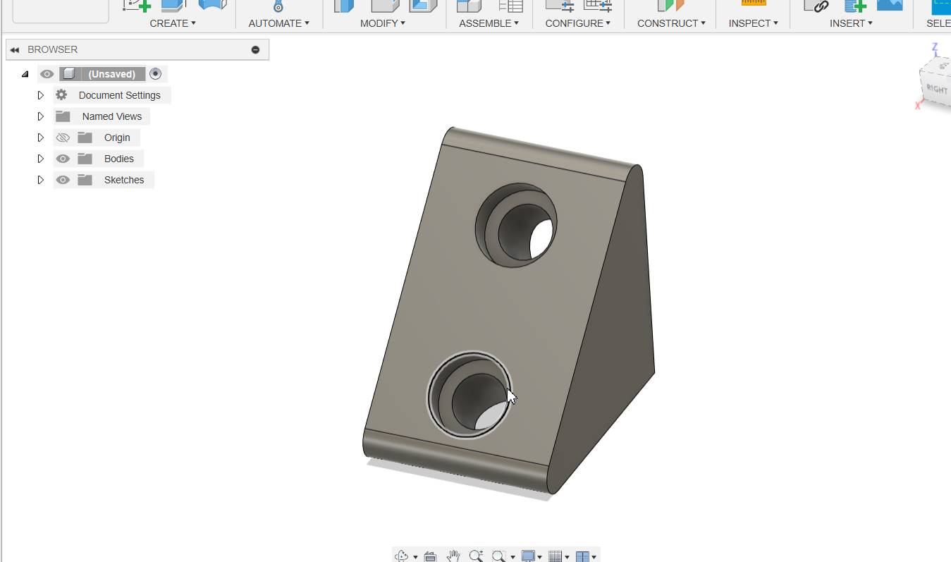
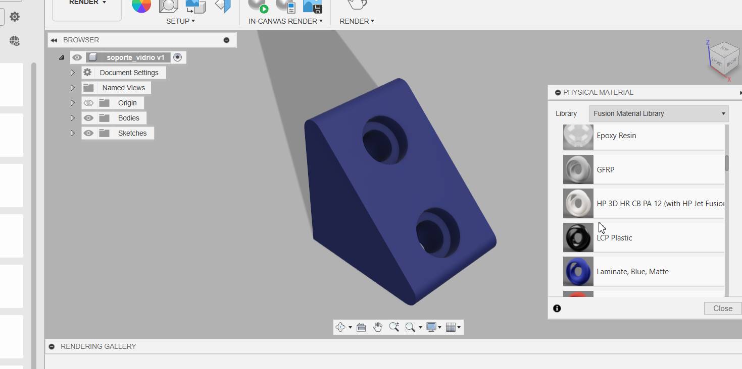
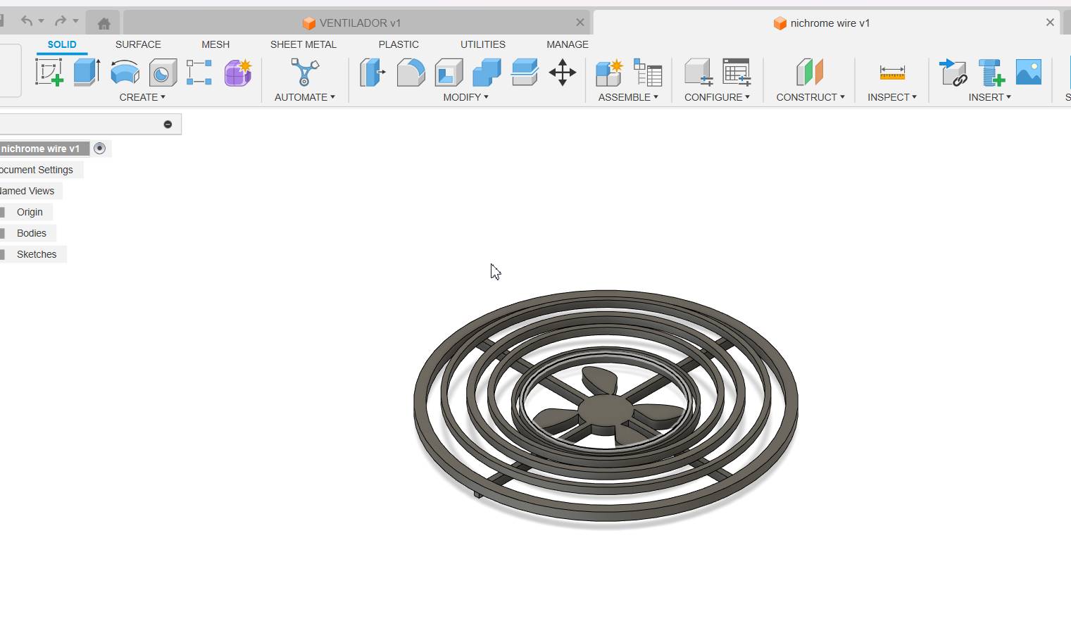
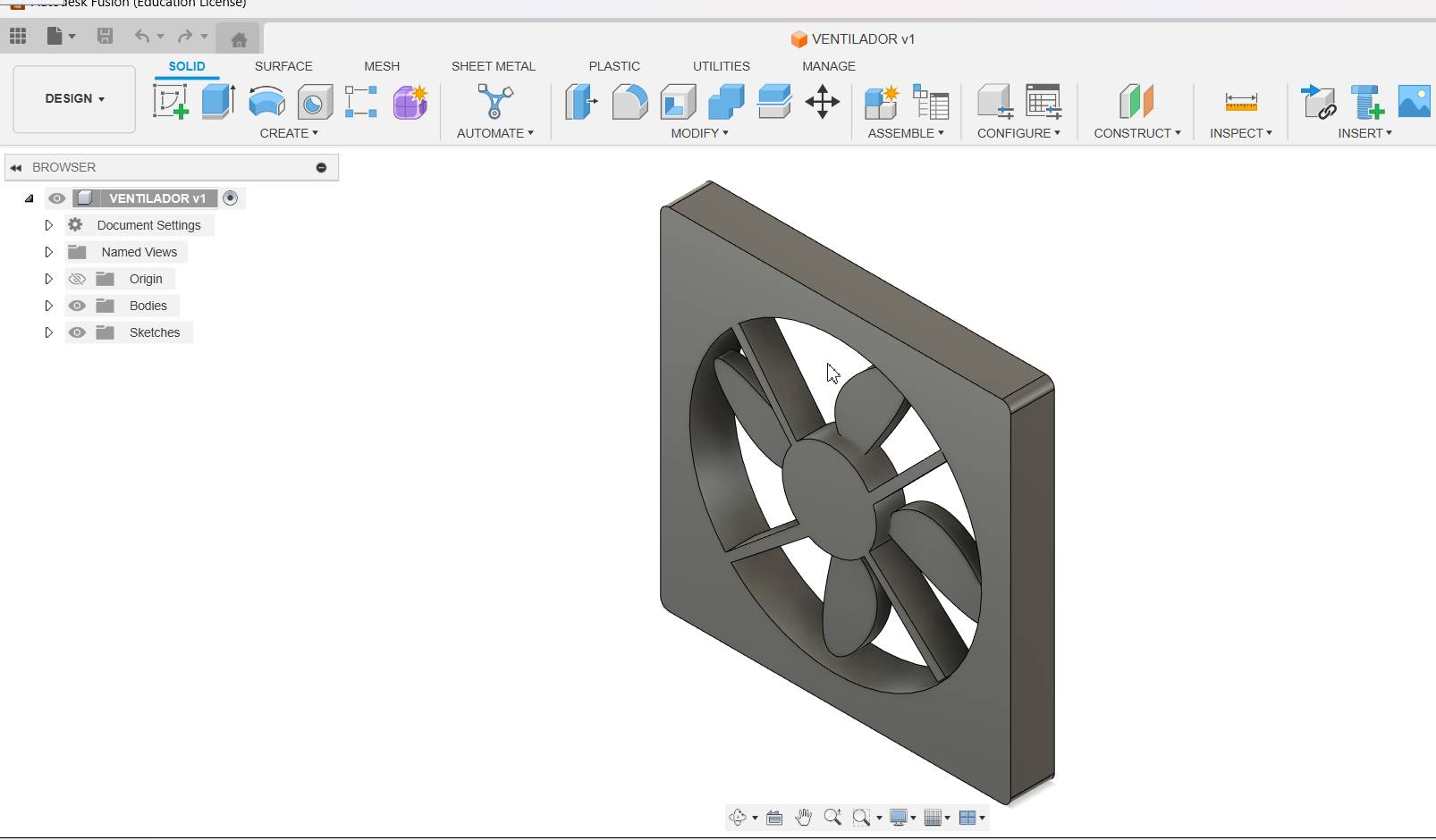
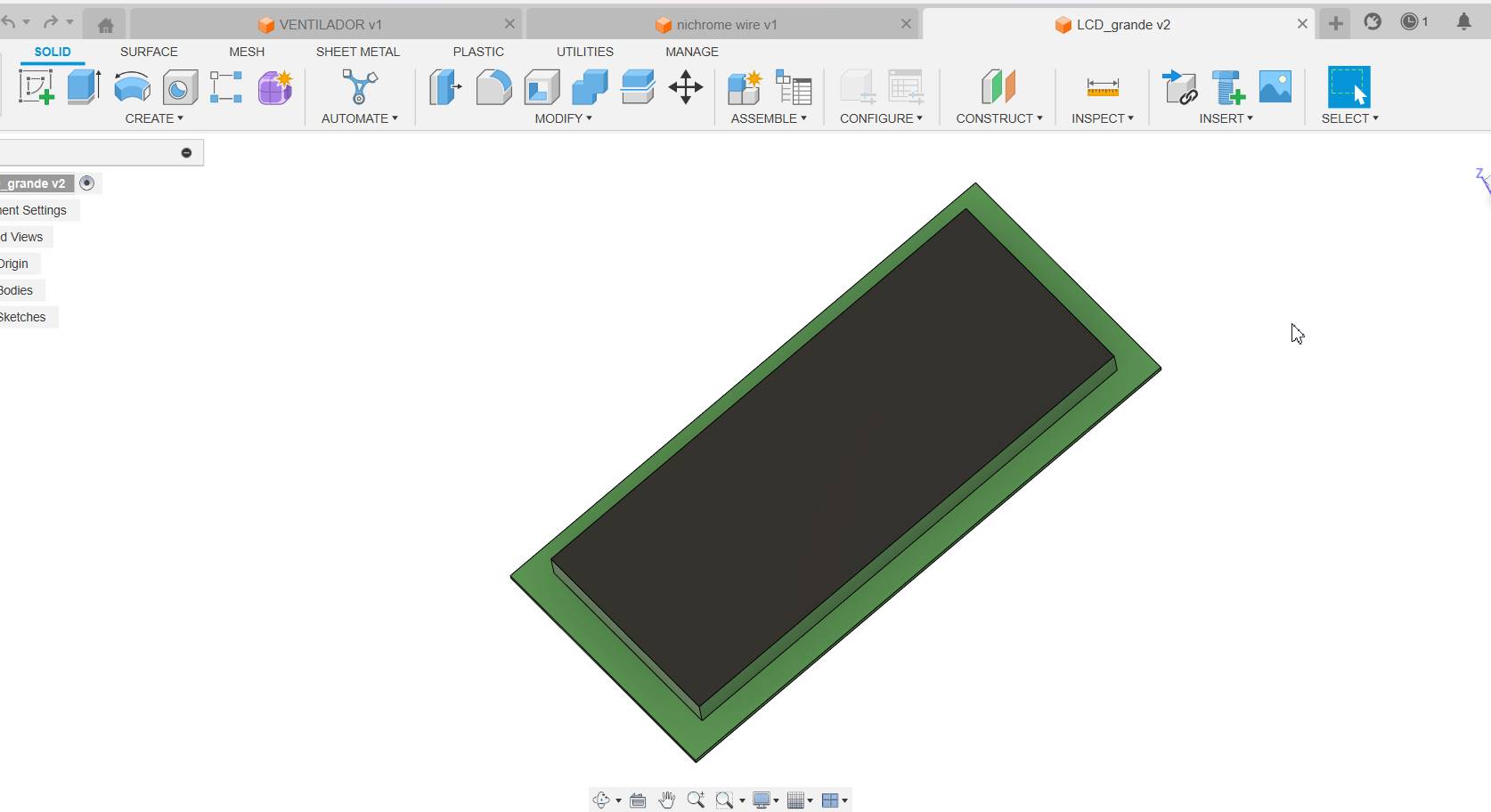
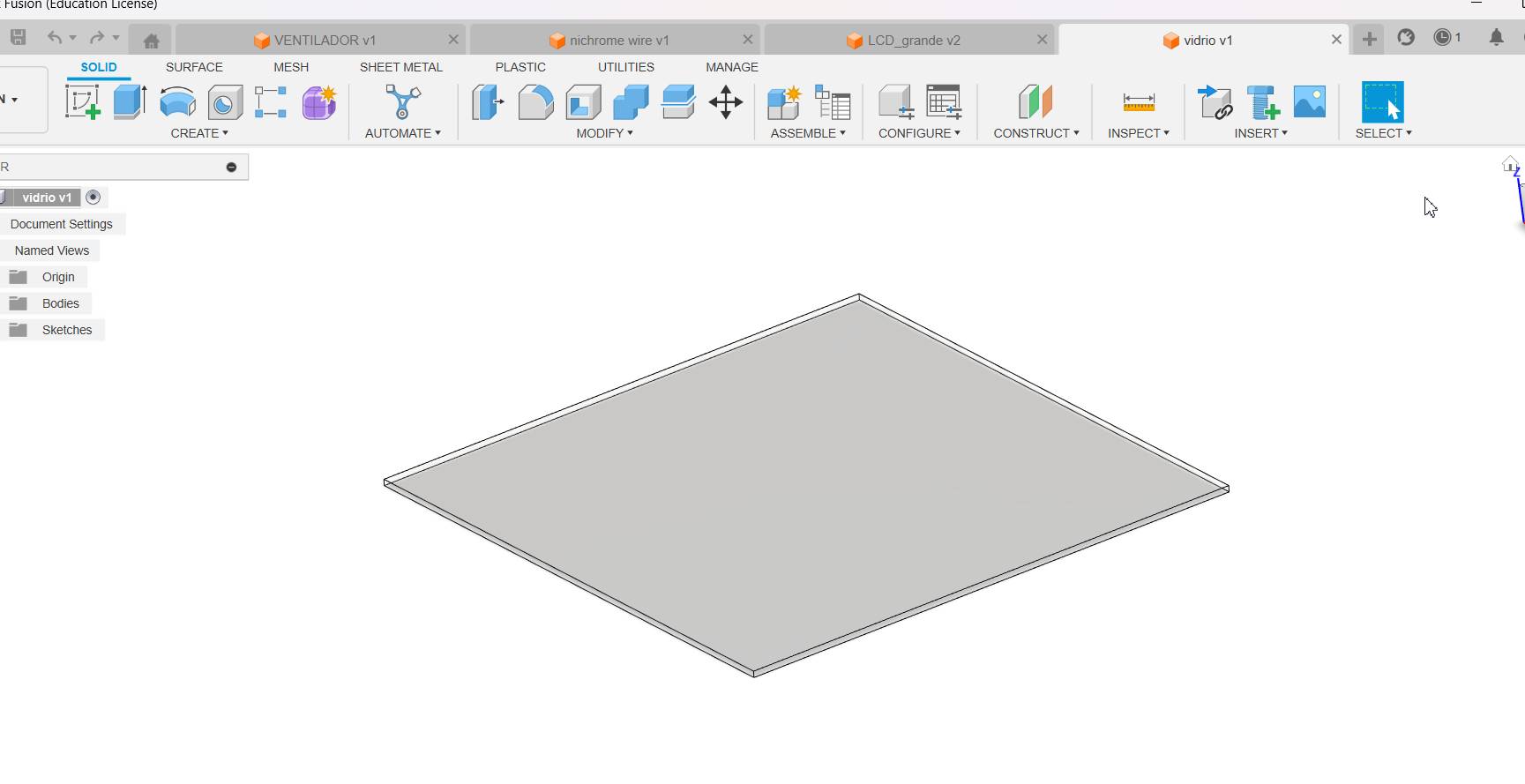
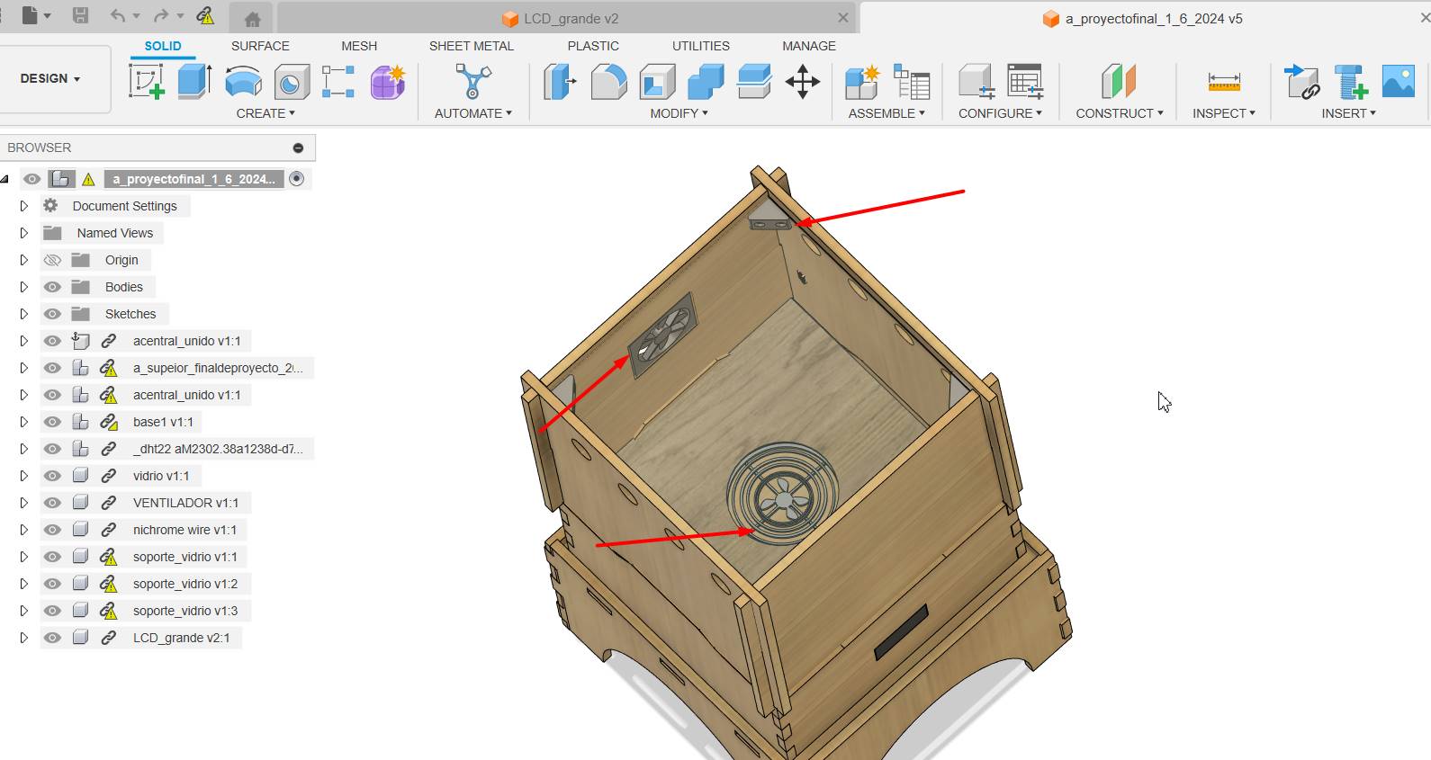
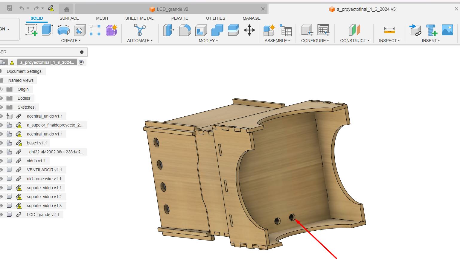
Final result


Final result
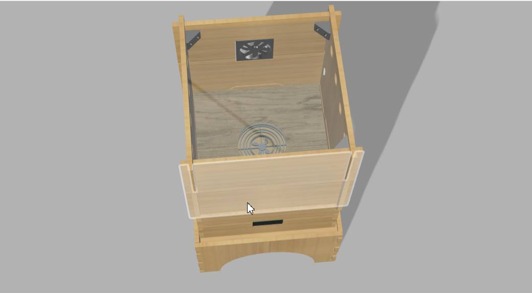
Final result
Week 03. computer controlled cutting
I used a recycled MDF, have a piece so we will use this for my prototype 1.
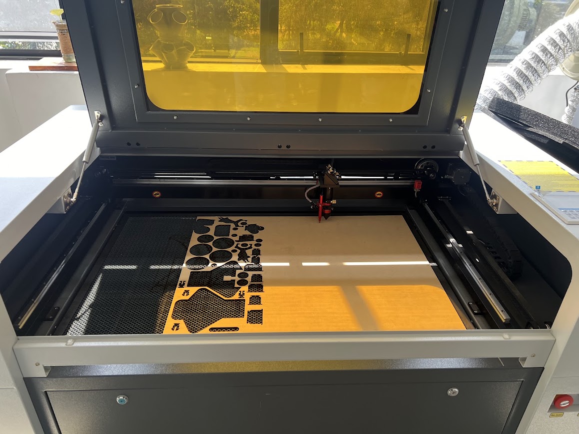
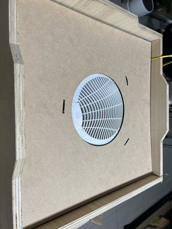
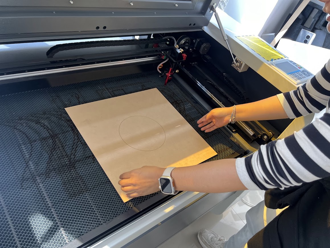
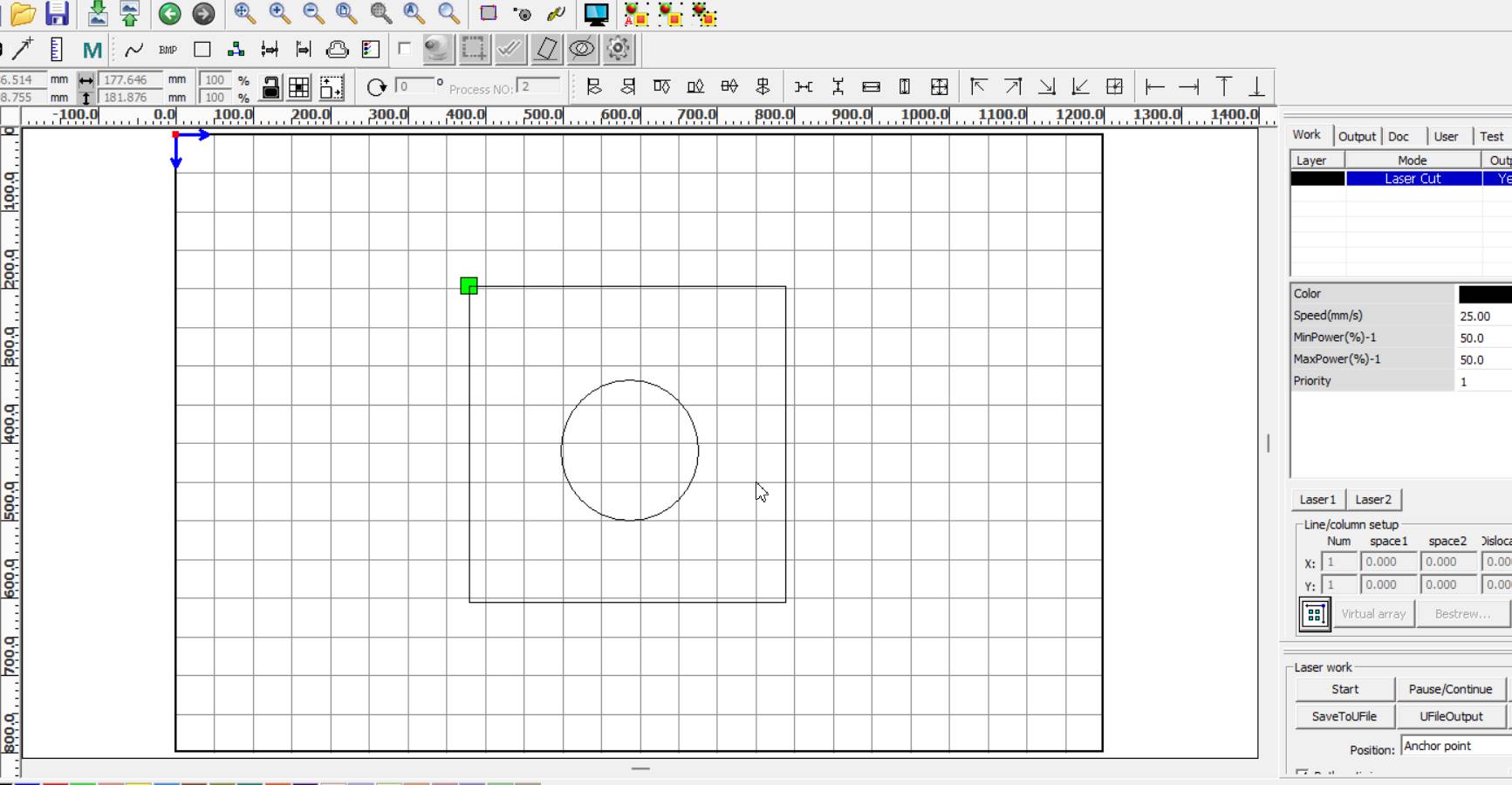
Here I made the design directly in rdwork, because it was a square that I measured exactly, and I made the circle with the measurement of my recycled heater.
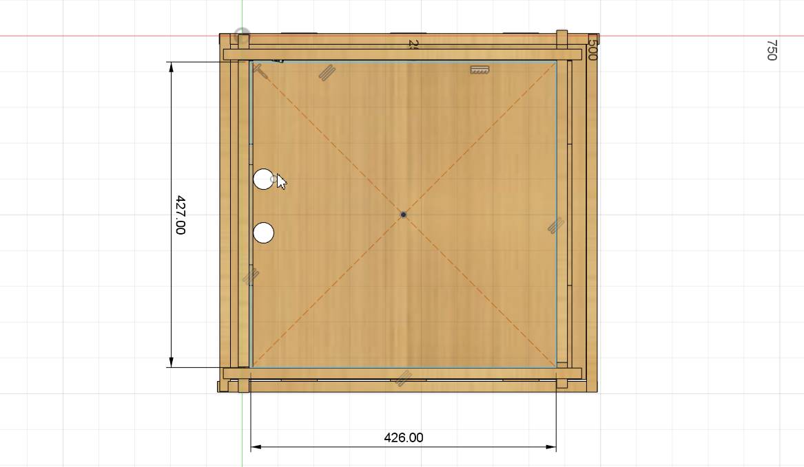
In this part of my 3D design we can see the measurements that are as they are of my module. Here I cut the box and the circle, I love that I can now do everything alone.
I was ready to fit

Here I fit perfectly!!! I will proceed to place support to divide the part where the heat will be and the part where the electronics will be.
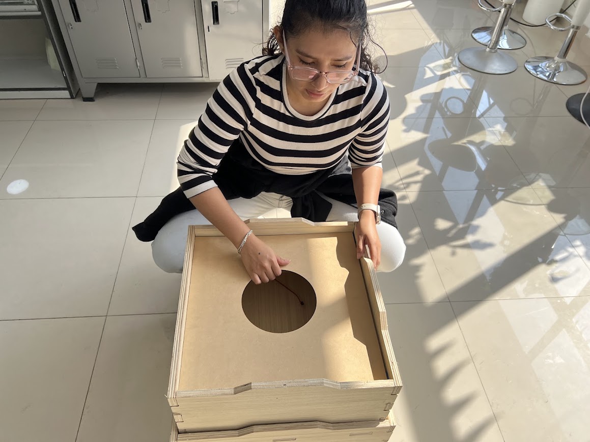
Placing your sticker to decorate
In the Fab Lab Toulouse Lautrec (Creatispace) There were pieces of vinyl that had been used for other events, there was just the color that I liked to decorate my module, it is a medium pink magenta and black color that they gave me from the Fab Lab of the University Scientist from the South, always kind to help me with my project.
In week 3 I had already cut vinyl, I really liked it and I learned to use it quickly, at first seeing the cutting depth depending on the material, and now I know the configuration for thin vinyl.
Here I designed my logo in Canva, I was thinking about the name and I wanted it to be read and understood what it is about, I chose some leaves that look like seeds to simulate plants and seeds


Here I pass the design for cutting the vinyl, first the black one and then the magenta sheets.

Here I place the magenta vinyl to make the cut of the leaves that look like seeds.

Here I placed the black color, but it had a part that was wrinkled and got stuck, so it was risky because I no longer had black vinyl, so I used the last piece and with faith!

It was achieved and I placed it with the base of the cutter
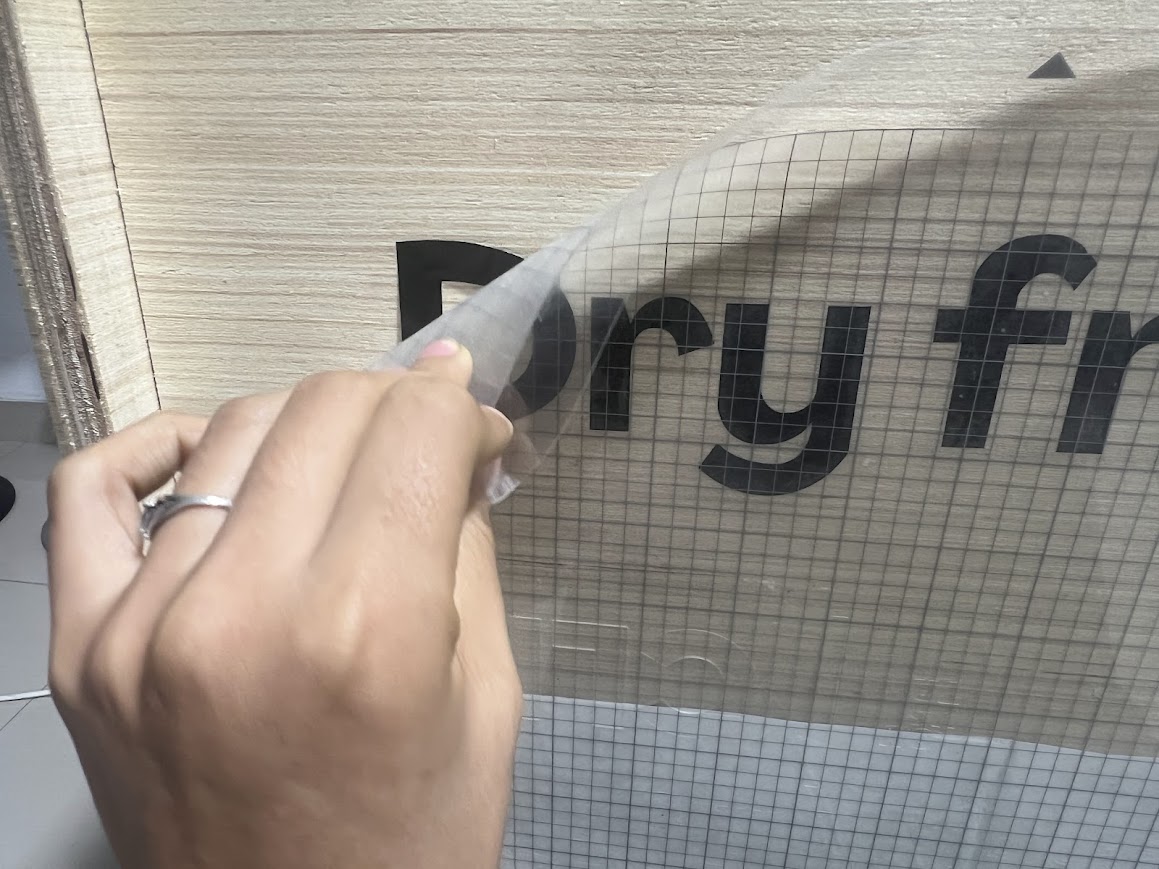
It was a good idea because I didn't have the transfer paper and couldn't find another way to do it and make it look good.

I did the same with the leaves that look like seeds and it turned out cute

place the Fab Lab logo at the bottom

Here I placed my Fab Lab Peru

Beautiful result, you know that I went to the Garage Lab laboratory very late at night because I couldn't handle the excitement of seeing how it would turn out and I couldn't wait until the next day to see the result! Love!
Week 05.3D scanning and printing

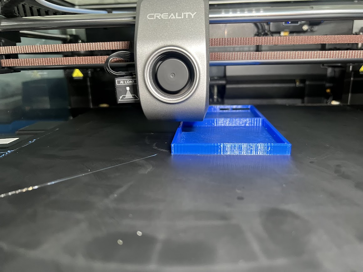
When printing it was fast, I did it in Garge lab on the k1max printer which prints very quickly.
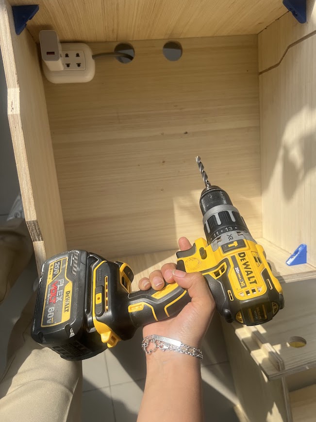
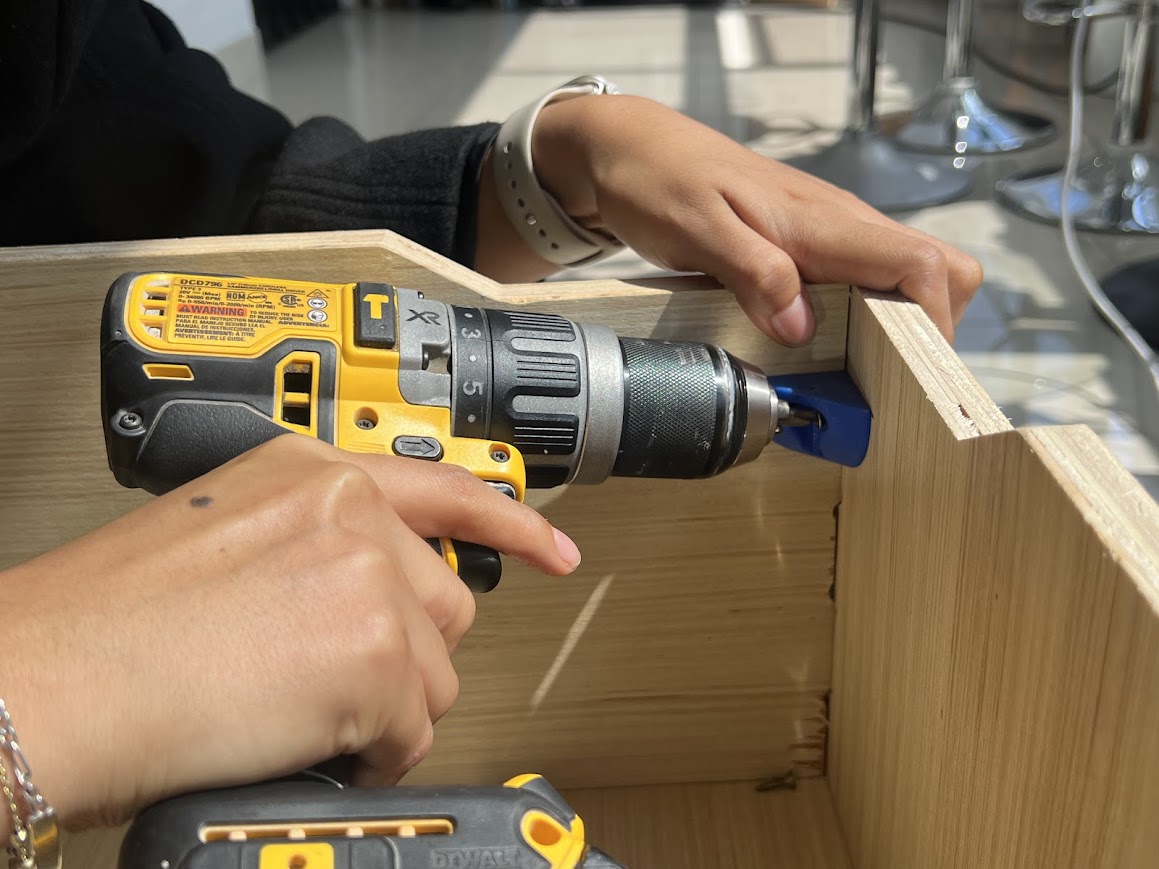
Here with the drill to place the printed supports, my pencil to mark, the bolts that I bought at the hardware store.

I changed the tip so I could bolt it.
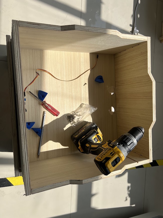
Since I already had it marked, I proceed to push.
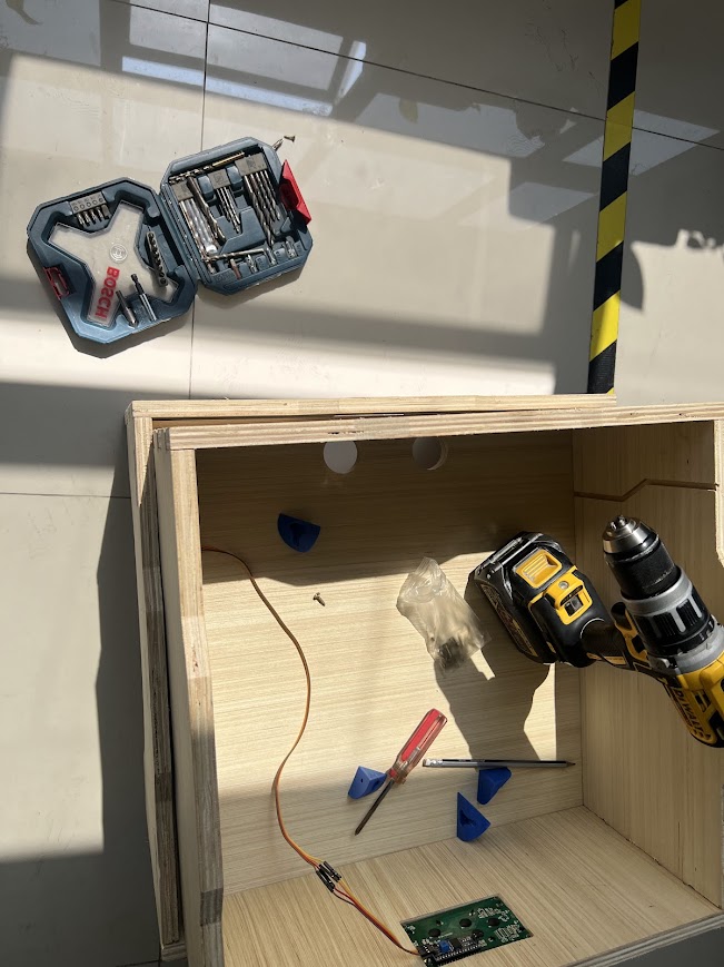
Here already pushing with the drill to push, everything is easier with this tool.
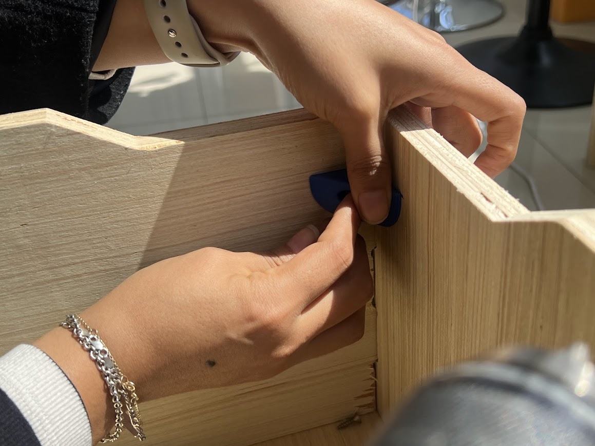
Gripping firmly, at first it was not bolting, but with more pressure it was achieved.
Now here I had my box printed for my components, and only used the box, not the lid, I should adapt it in my next versions.
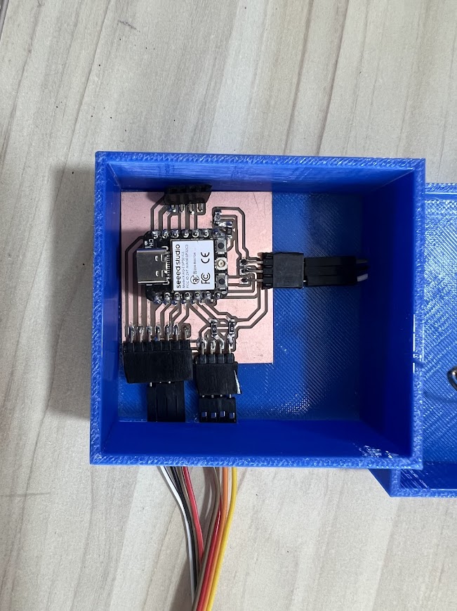
I fit everything, somewhat tight, it seems to me that I should enlarge but then I analyze that it could be loose.
Week 07.3D Computer controlled machiningn
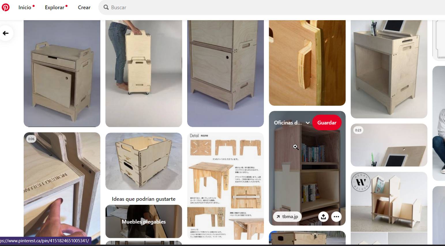
I got my inspiration from Pinterest, I looked for models of nestable and modular boxes.
Starting to design in Autocad, first the parts that we are going to start fitting together.

Since I wanted it to fit under pressure, the measurements had to be exact, of course I would have to sand a little later because I wanted it to fit under pressure and it was achieved.
Here I was checking the fittings to see which is the best fit.

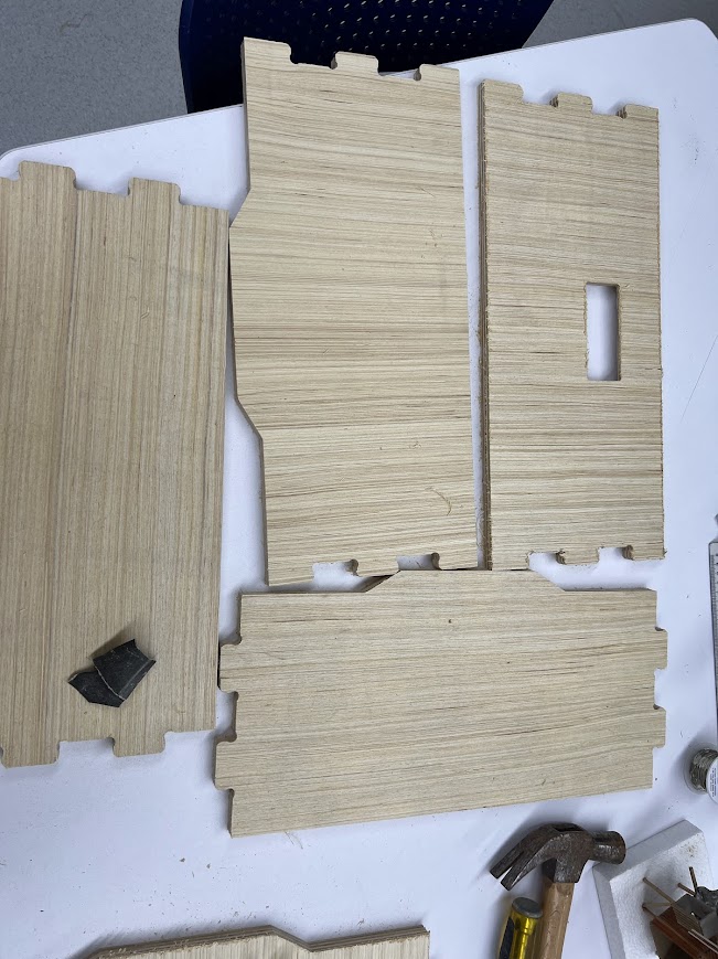
Here with the help of Hans we put the pressed plywood and secured all the sides, here remember to be careful not to pass the cutter over the fasteners.

First we make internal trimming of the smallest pieces.

to then be able to cut the pieces, here I was confused about the size of the fan so we had to cut that part again.

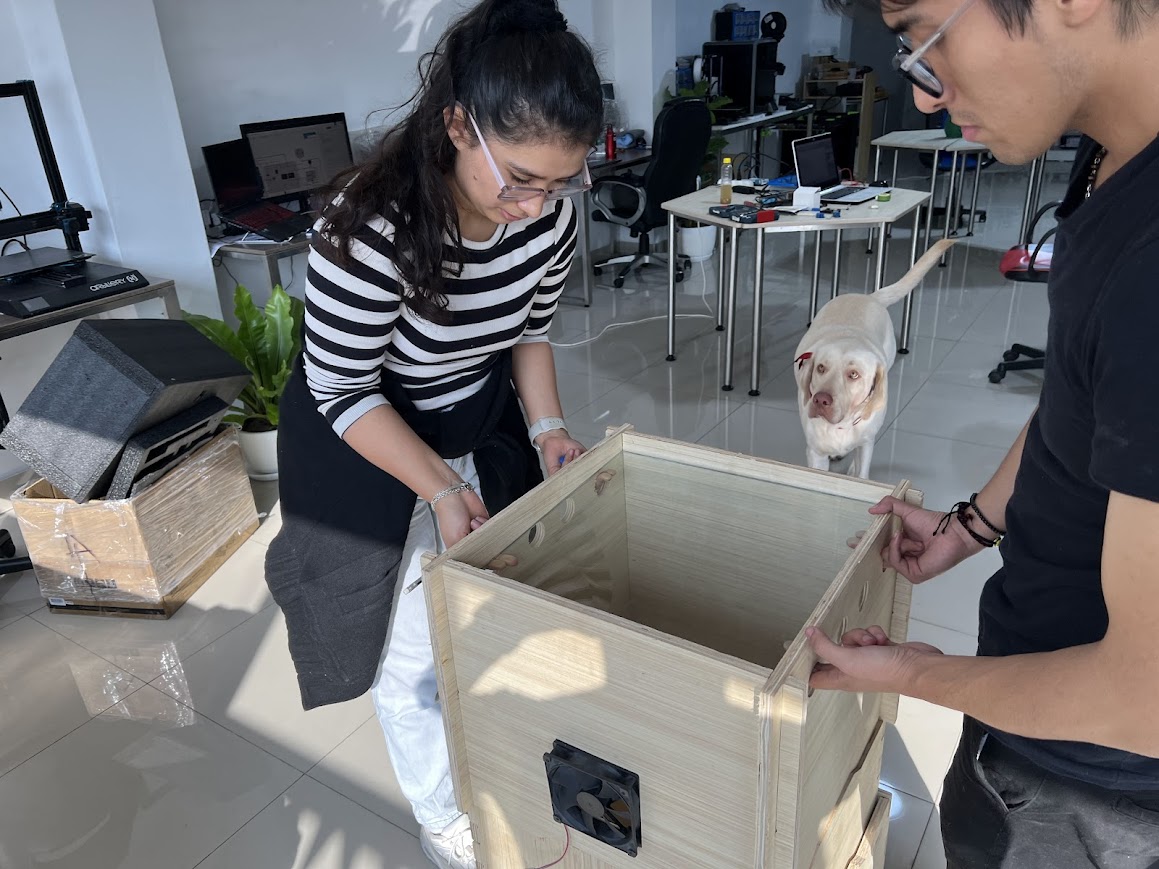
Fit everything before sanding it and it turned out very well.

Here I see what I have to sand to make the fan fit well.

Here I was making the cut where the screen is, fitting by pressure.


Here in this joint after the week of making our own furniture we learned a lot and I wanted to use that knowledge in my final project

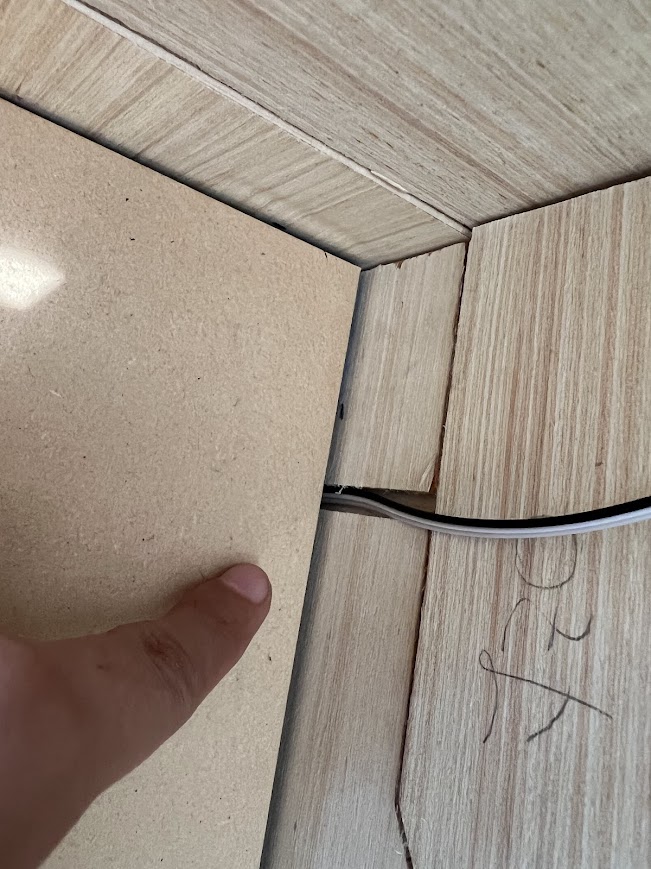
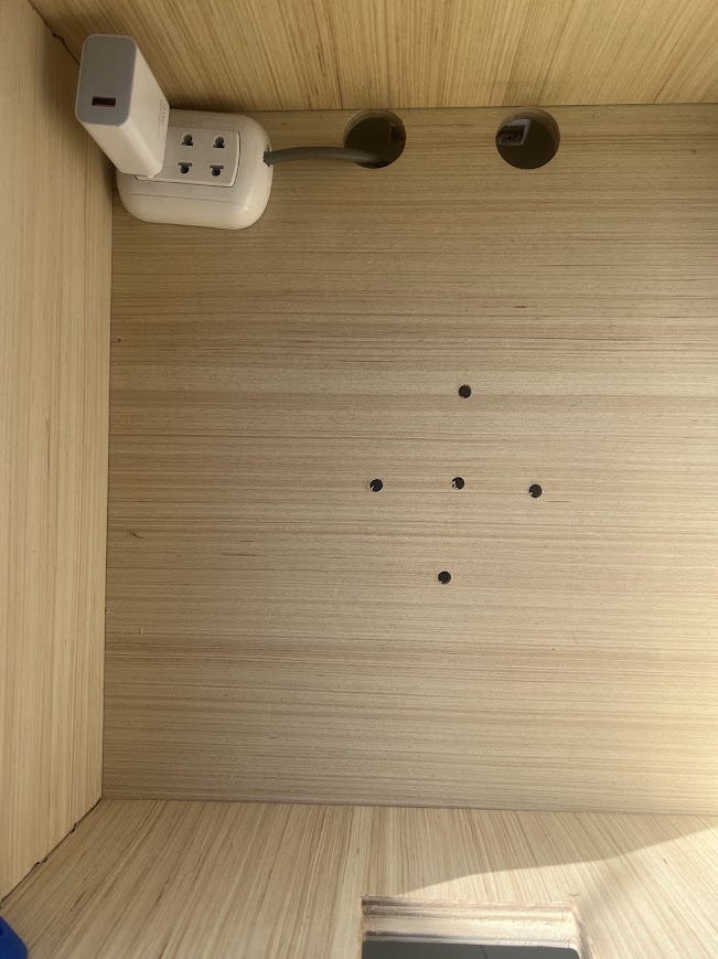
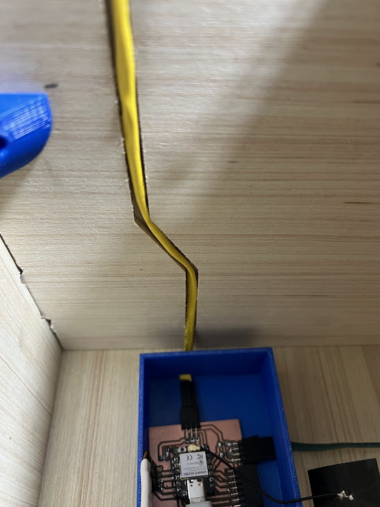
Everything fits perfectly, I put two holes there so I can pass my cables through there.

At this point, I failed in one part, in scraps to be able to make the center part of my module where all the electronics and connections will go.

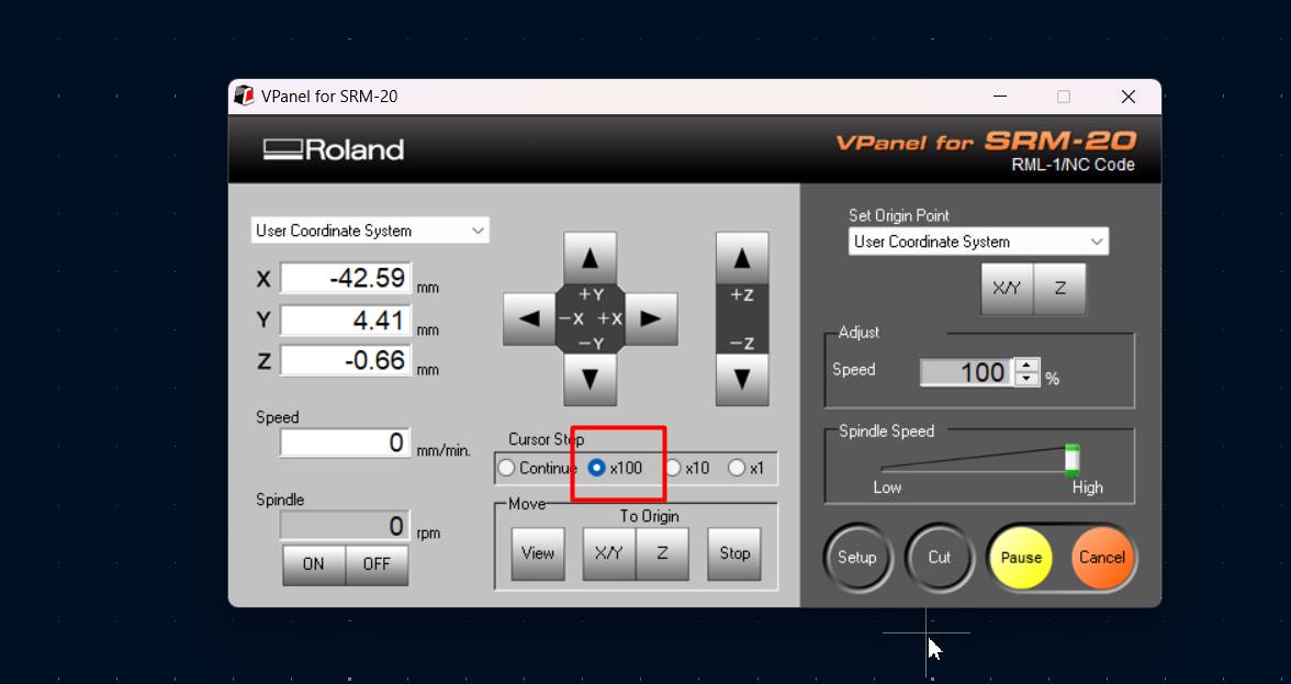
We calibrate the machine first

At this point, I failed in one part, in scraps to be able to make the center part of my module where all the electronics and connections will go.

We calibrate the machine first

At this point, I failed in one part, in scraps to be able to make the center part of my module where all the electronics and connections will go.

We calibrate the machine first

At this point, I failed in one part, in scraps to be able to make the center part of my module where all the electronics and connections will go.

We calibrate the machine first

At this point, I failed in one part, in scraps to be able to make the center part of my module where all the electronics and connections will go.

We calibrate the machine first
Week 08.3D Electronic design


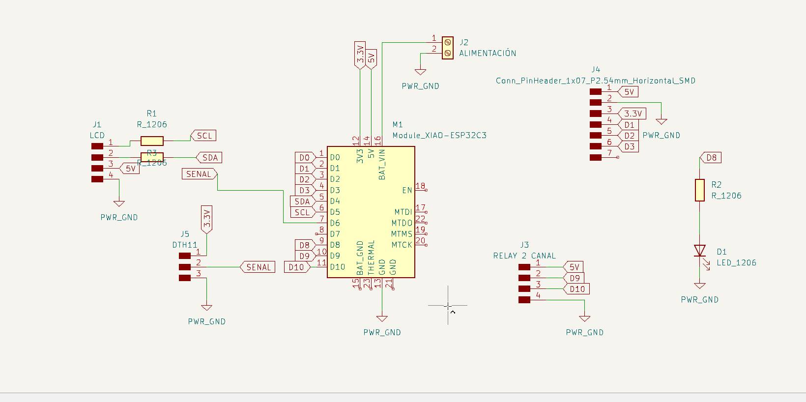

Final result

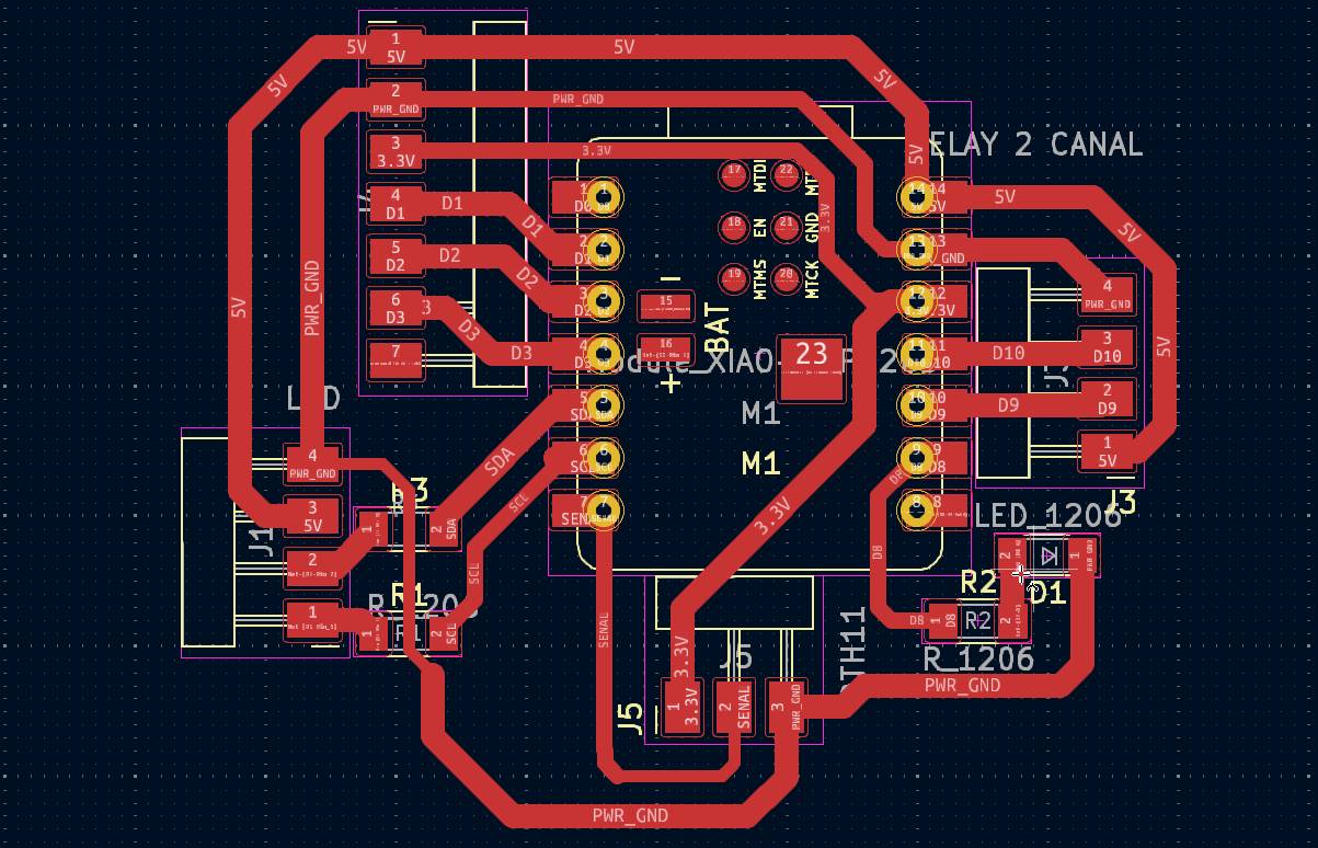
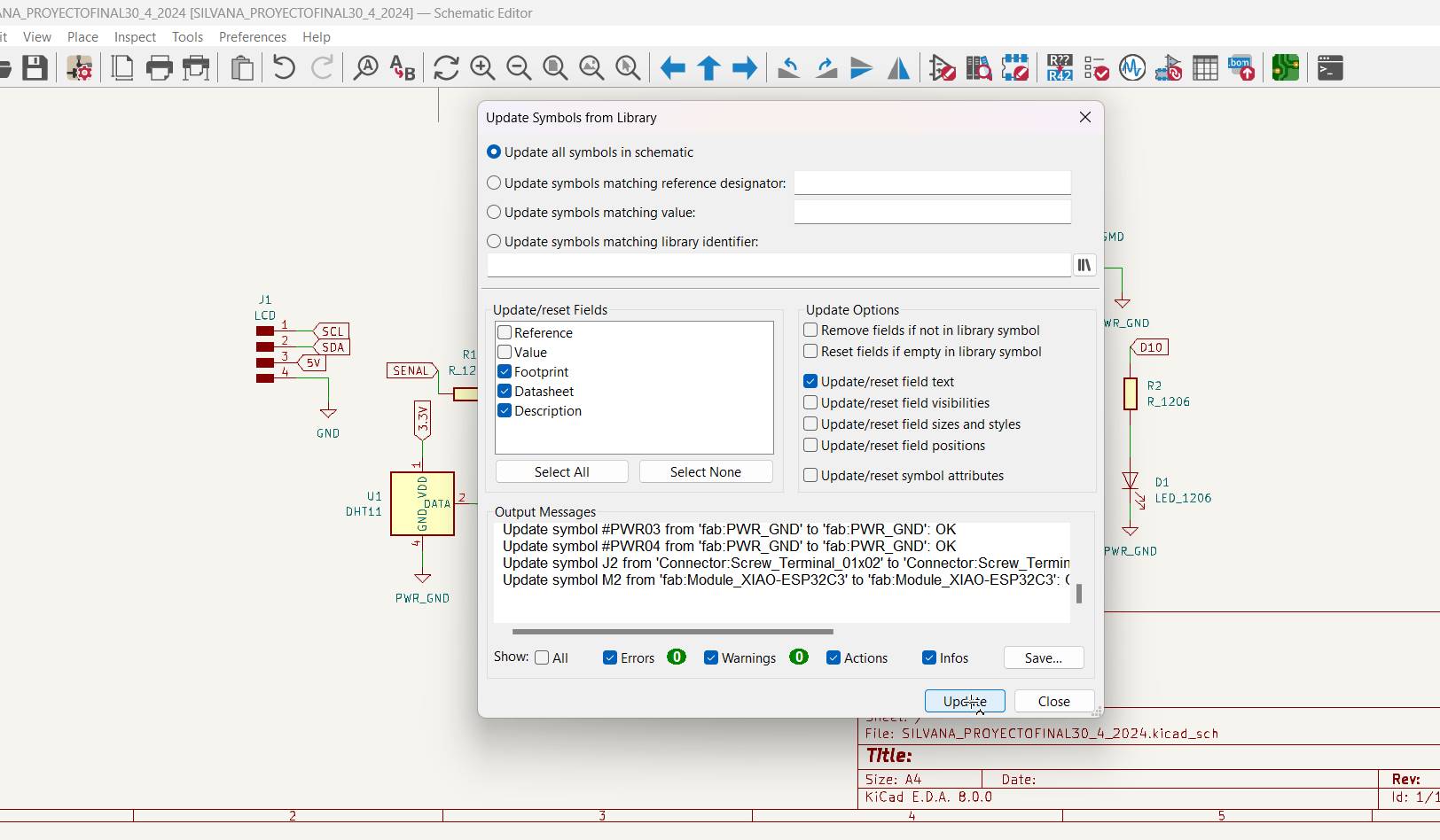
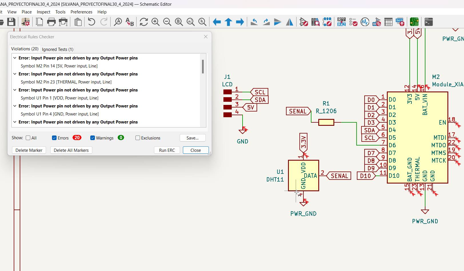
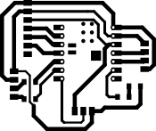
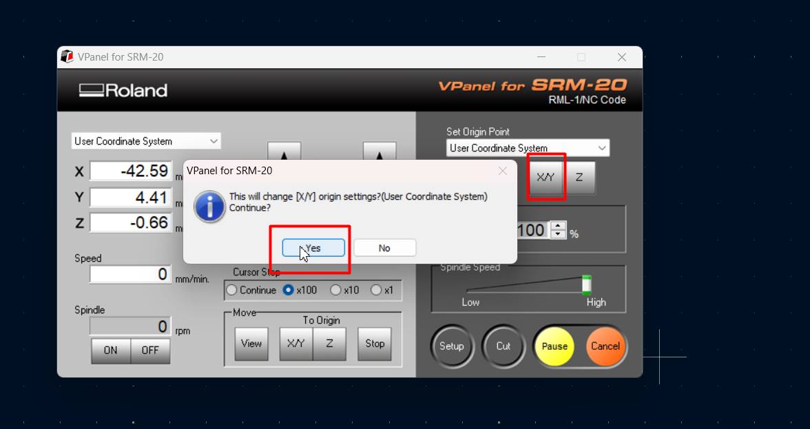
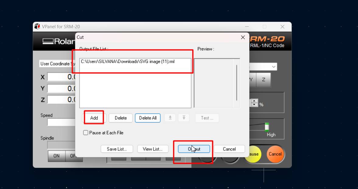
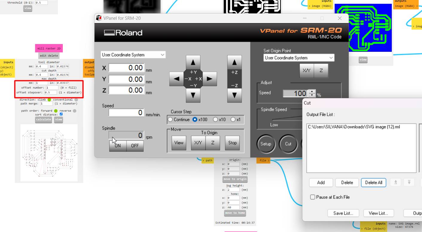
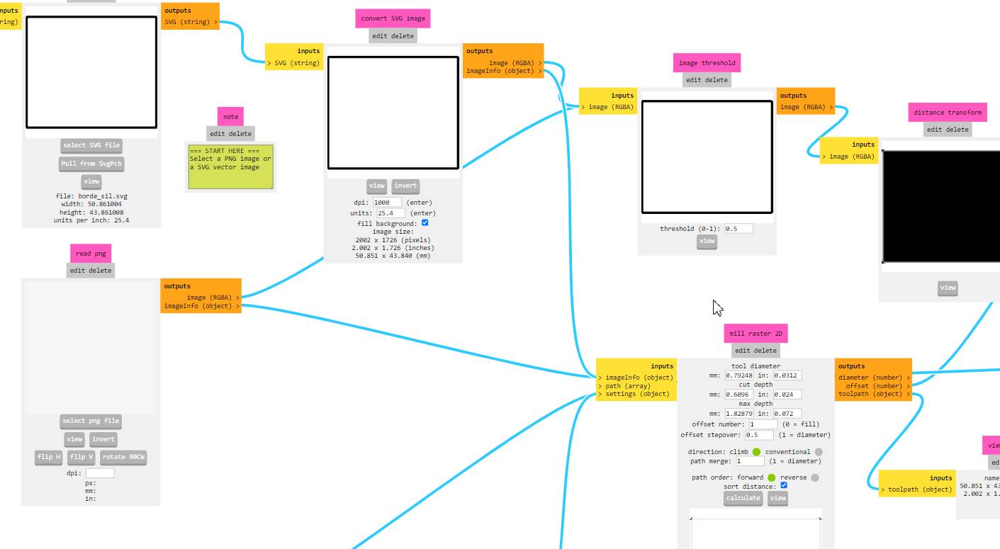
Milling & Soldering the Board
Week 08.3D Embedded programming
#include "DHTesp.h"
#include < LiquidCrystal_I2C.h>

#define DHTPIN D6            // Pin del sensor DHT11
#define DHTTYPE DHTesp::DHT11   // Tipo de sensor DHT11

DHTesp dht;
LiquidCrystal_I2C lcd(0x27, 21, 4);

void setup() {
  // Initialize serial communication for debugging purposes
  Serial.begin(9600);
  delay(1500);

  // Initialize DHT sensor
  dht.setup(DHTPIN, DHTTYPE);

  // Initialize the LCD
  lcd.init();
  lcd.backlight();

  // Set pin modes
  pinMode(D9, OUTPUT); // CALEFA
  pinMode(D10, OUTPUT); // VENTI
}

void loop() {
  delay(2000);

  float hum = dht.getHumidity();
  float temp = dht.getTemperature();

  if (isnan(hum) || isnan(temp)) {
    Serial.println("Error al leer el sensor DHT11!");
    return;
  }

  // Display temperature and humidity on the LCD
  lcd.clear();
  lcd.setCursor(0, 0);
  lcd.print("Temperature: ");
  lcd.print(temp);
  lcd.print(" C");

  lcd.setCursor(0, 1);
  lcd.print("Humidity: ");
  lcd.print(hum);
  lcd.print(" %");

  // Control heating and ventilation based on temperature
  if (temp > 45) {
    digitalWrite(D10, LOW);  // Turn off ventilation
    digitalWrite(D9, HIGH);  // Turn on heating
  } else {
    digitalWrite(D10, HIGH); // Turn on ventilation
    digitalWrite(D9, LOW);   // Turn off heating
  }

  delay(200); // Short delay for debounce
}
Code
Week 11.3D Input devices
Final Project Test
Digital sensors with DTH11
Program
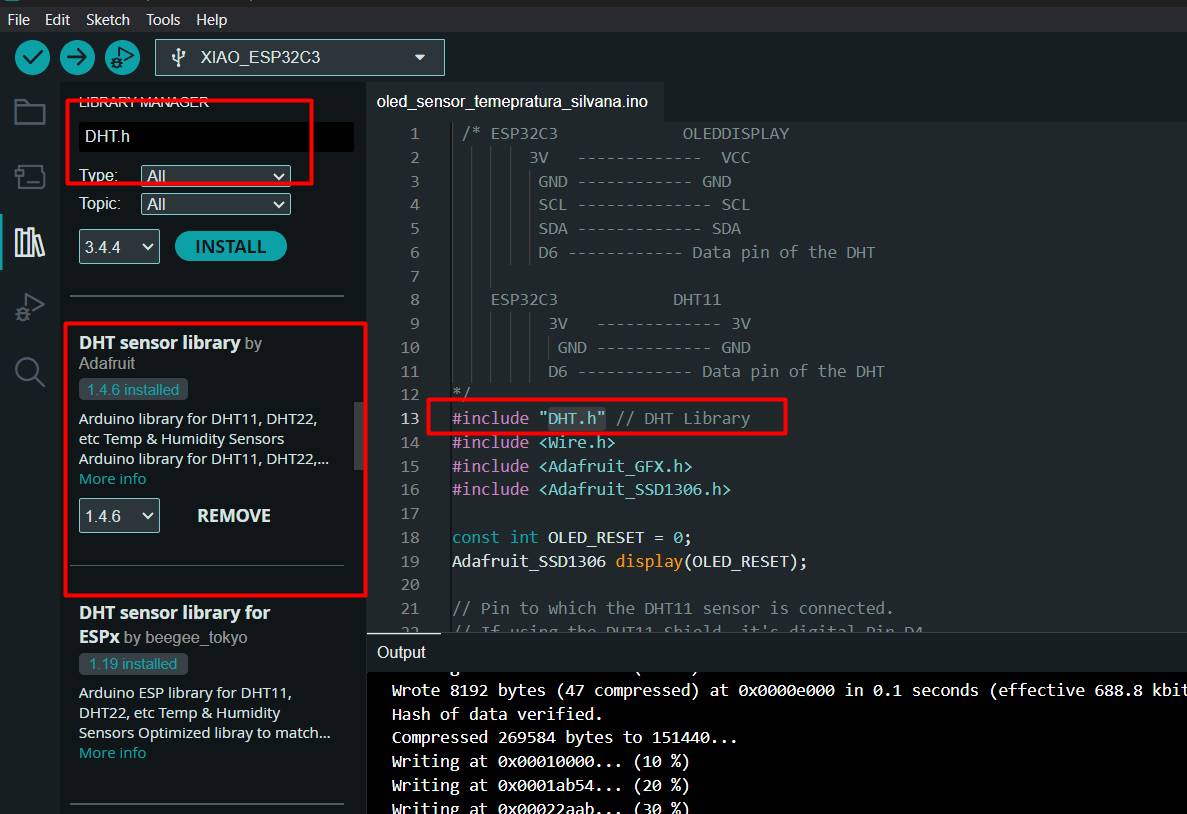
To make sure I got accurate readings from my DHT sensor on the Arduino, I installed the DHT.h library carefully and correctly. First, I opened the Arduino IDE and navigated to the "Sketch" menu, then "Include Library" and finally "Manage Libraries". In the search box, I entered "DHT" and found Adafruit's DHT Sensor Library. After selecting it, I clicked "Install" and waited for the process to complete.
Code
 /* ESP32C3             OLEDDISPLAY
        3V   -------------  VCC
         GND ------------ GND
         SCL -------------- SCL
         SDA ------------- SDA
         D6 ------------ Data pin of the DHT

    ESP32C3            DHT11
          3V   ------------- 3V
           GND ------------ GND
          D6 ------------ Data pin of the DHT
*/
#include "DHT.h" // DHT Library
#include < Wire.h >
#include < Adafruit_GFX.h>
#include < Adafruit_SSD1306.h>

const int OLED_RESET = 0;
Adafruit_SSD1306 display(OLED_RESET);

// Pin to which the DHT11 sensor is connected.
// If using the DHT11 Shield, it's digital Pin D4.
const int DHTPIN = D6;

// Specify the type of DHT sensor being used.
#define DHTTYPE DHT11

// Initialize the sensor with the pin and type.
DHT dht(DHTPIN, DHTTYPE);

void setup() {
  Serial.begin(115200); // Begin serial communication at 9600 Baud.
  Wire.begin();

  display.begin(SSD1306_SWITCHCAPVCC, 0x3C);
  display.display();
  delay(2000);
  display.clearDisplay();
  dht.begin(); // Start DHT communication.
}

void loop() {
  // The DHT11 sensor provides a new reading every 2 seconds,
  // so there's no need to constantly loop in the program.
  delay(2000);

  // Read humidity value.
  double humidity = dht.readHumidity();
  // Read temperature in Celsius.
  double temperatureC = dht.readTemperature();
  // Read temperature in Fahrenheit.
  // The boolean parameter controls whether
  // the temperature is displayed in Fahrenheit or Celsius.
  double temperatureF = dht.readTemperature(true);

  // Check if the values were read successfully.
  if (isnan(humidity) || isnan(temperatureC) || isnan(temperatureF)) {
    Serial.println("Error reading data.");
    return;
  }

  display.clearDisplay();
  display.setTextSize(1);
  display.setTextColor(WHITE);

  display.setCursor(5, 0);
  display.println("Fab Academy");

  display.setCursor(5, 15);
  String tempValue = String(temperatureC);
  display.println("Temp: " + tempValue + "C");

  display.setCursor(5, 23);
  String humValue = String(humidity);
  display.println("Humidity: " + humValue + "%");

  display.display();
  delay(500);
}
Week 16.3D System integration
You can see it here since it is an integration of everything I was seeing, I will not post it because it repeats some parts of what I already posted, I want to maintain order, in the same way I leave you my week 16
Here I will show you photos of the step by step I did to assemble my fruit dryer module.
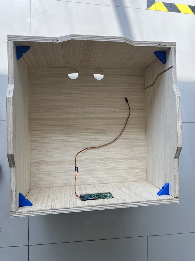
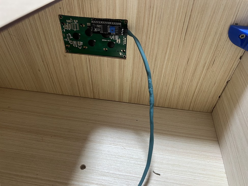
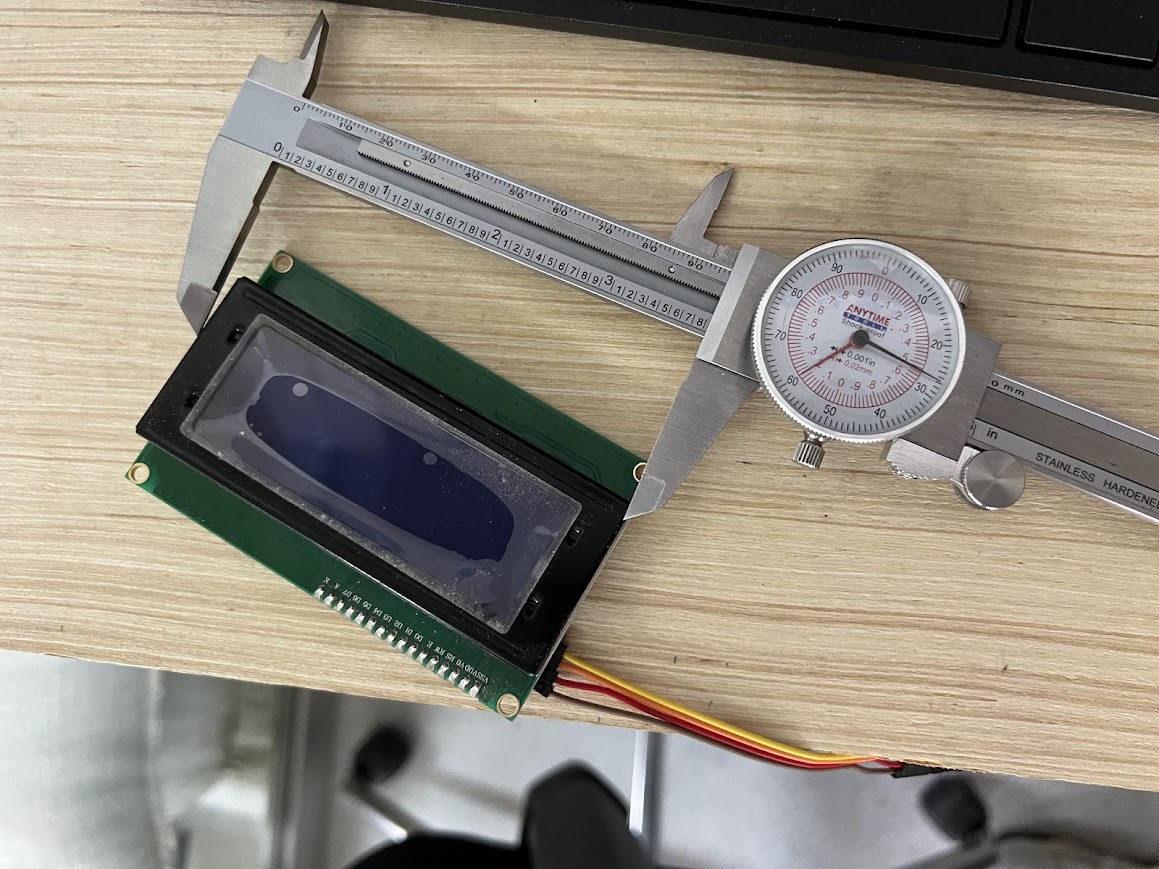
General Characteristics of the I2C LCD Module Screen:
- Type: LCD (Liquid Crystal Display)
- Common sizes: 16x2 (16 characters per 2 rows) and 20x4 (20 characters per 4 rows)
- Backlight: LED with on/off control
I2C module:
- Common driver chip: PCF8574
- I2C Address: Generally configurable via solder jumpers (typically between 0x20 and 0x27)
Here thinking about how I could improve this system for my next versions, I could add handles, in the videos you will see how the glass is removed and placed.
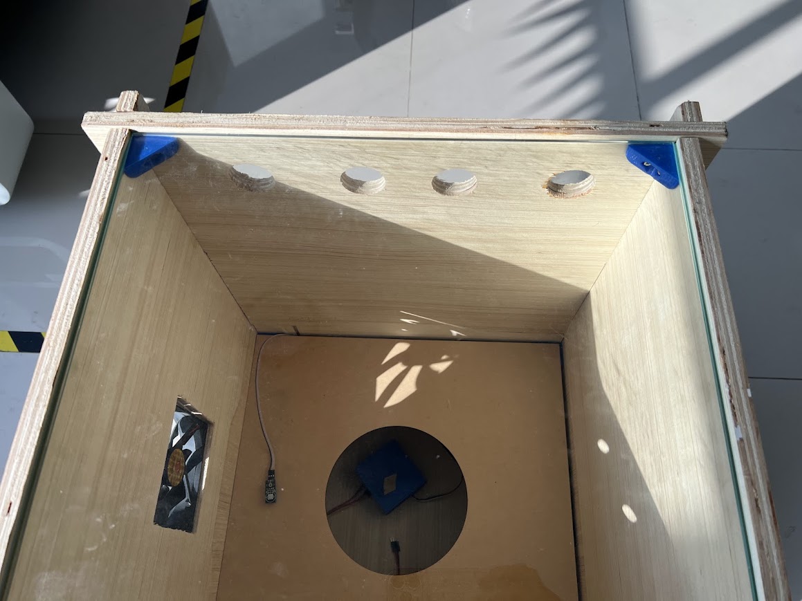
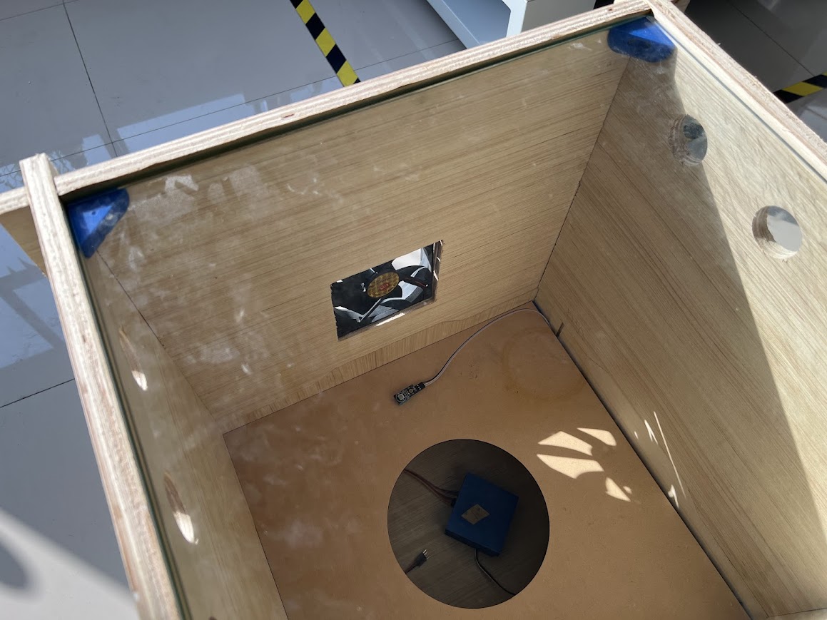
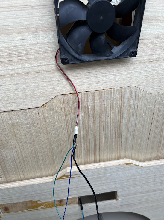
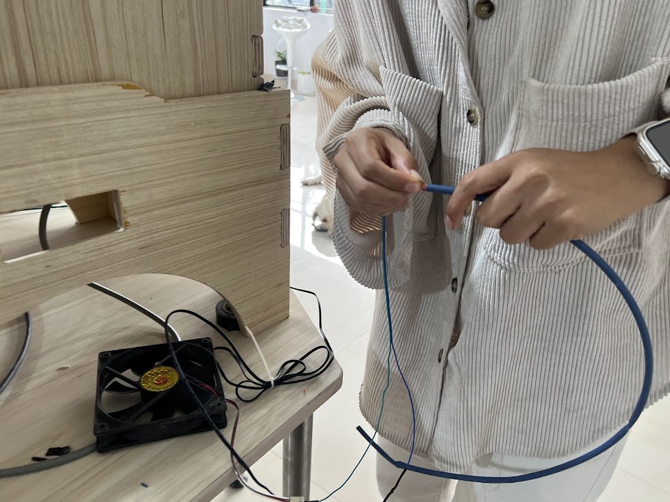
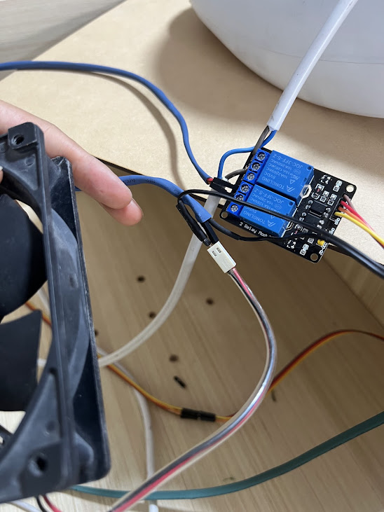
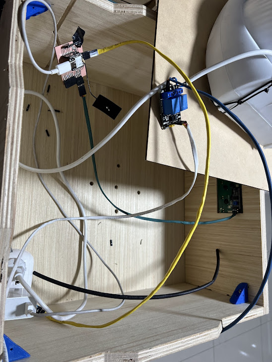
We can see the heater open, I was adjusting the fan because it had moved, I think, and it was crashing, which is why it did not work, with the adjustment everything worked together again, because it was only heating and it could be a danger because the heat was not going to be directed In a sense, if not, it could heat in a non-homogeneous way, since with the fan running it was safer and he decided to place the entire structure since it is adapted for that type of temperatures.
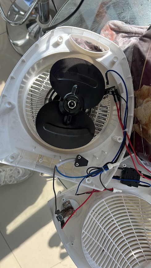
Nichrome wire with fan
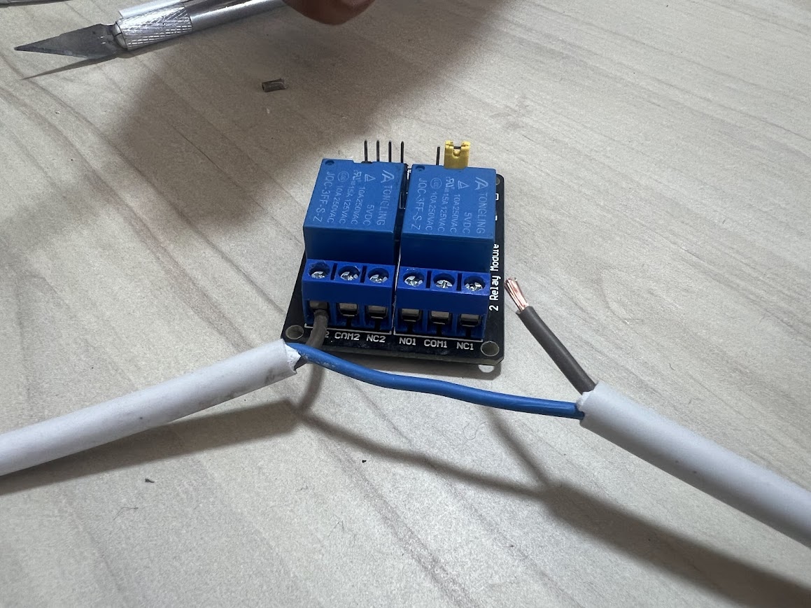
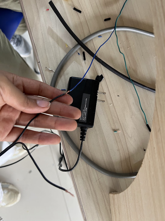
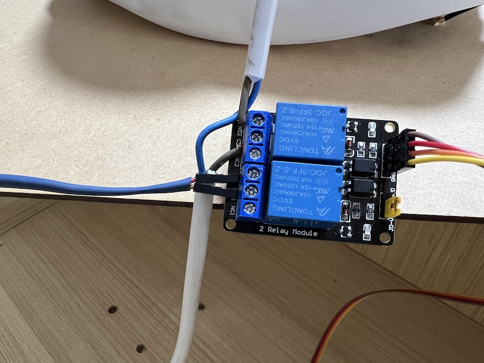
Here I wanted to add something very important to my research, this heater was recycled for this project, I was always thinking that another material could help me generate heat in my drying, and I also consulted with some engineers to support me with some ideas for generating heat. heat, for this first prototype I used the heater with nichrome wire and a fan, it is focused on relay, now I will tell you its details.

1.Nichrome is a material with high electrical resistance and can withstand high temperatures without oxidizing quickly, making it ideal for use in my project.
2. When an electric current is applied to the nichrome wire, due to its high resistance, it converts electrical energy into heat (Joule effect). This heat is generated uniformly along the thread, allowing for homogeneous heat.
3. The amount of heat generated depends on the length of the wire, its thickness, and the amount of current applied to it. Control systems, such as thermostats or temperature controllers, can adjust the current to maintain the desired temperature as I did, controlling a low temperature so as not to affect the base of my module.
Nichrome wire heaters are used in a variety of devices, such as hair dryers, toasters, and in your case, temperature control systems for drying fruit.
Nichrome is a material with high electrical resistance and can withstand high temperatures without oxidizing quickly, making it ideal for use in my project. When an electric current is applied to the nichrome wire, due to its high resistance, it converts electrical energy into heat (Joule effect). This heat is generated uniformly along the thread, allowing for homogeneous heat. The amount of heat generated depends on the length of the wire, its thickness, and the amount of current applied to it. Control systems, such as thermostats or temperature controllers, can adjust the current to maintain the desired temperature as I did, controlling a low temperature so as not to affect the base of my module. Nichrome wire heaters are used in a variety of devices, such as hair dryers, toasters, and in your case, temperature control systems for drying fruit. The nichrome thread is structure that thermally insulates the thread from the rest of the device, to ensure that heat is directed where it is needed. In addition, an insulating material is used to avoid short circuits and maintain the safety of the system, with cables that withstand heat.
In this system, a fan was used to distribute heat evenly and prevent overheating in specific areas.
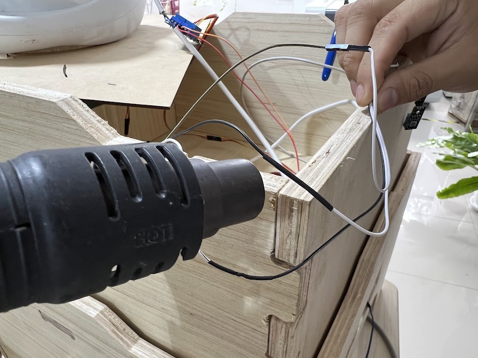
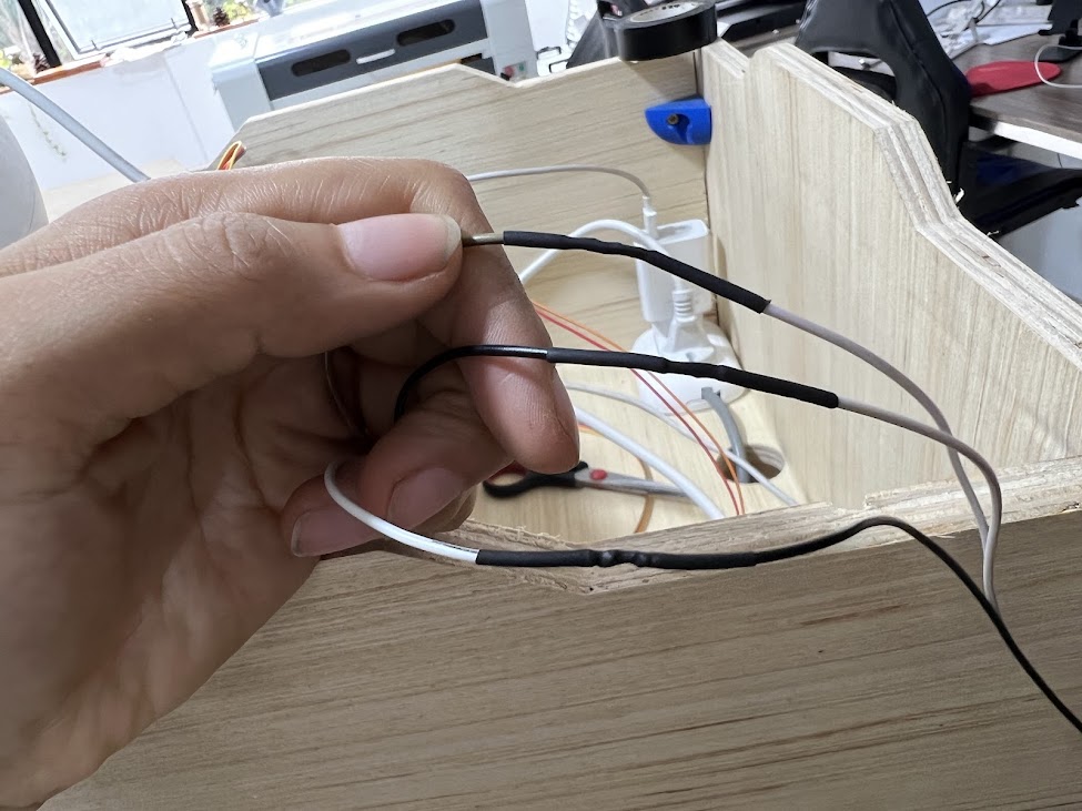
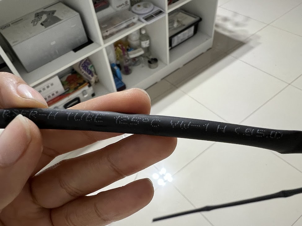
Here are the characteristics of the heat shrinkable that indicate that it resists 125°C.
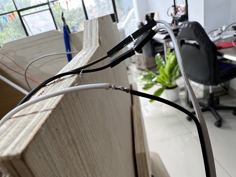
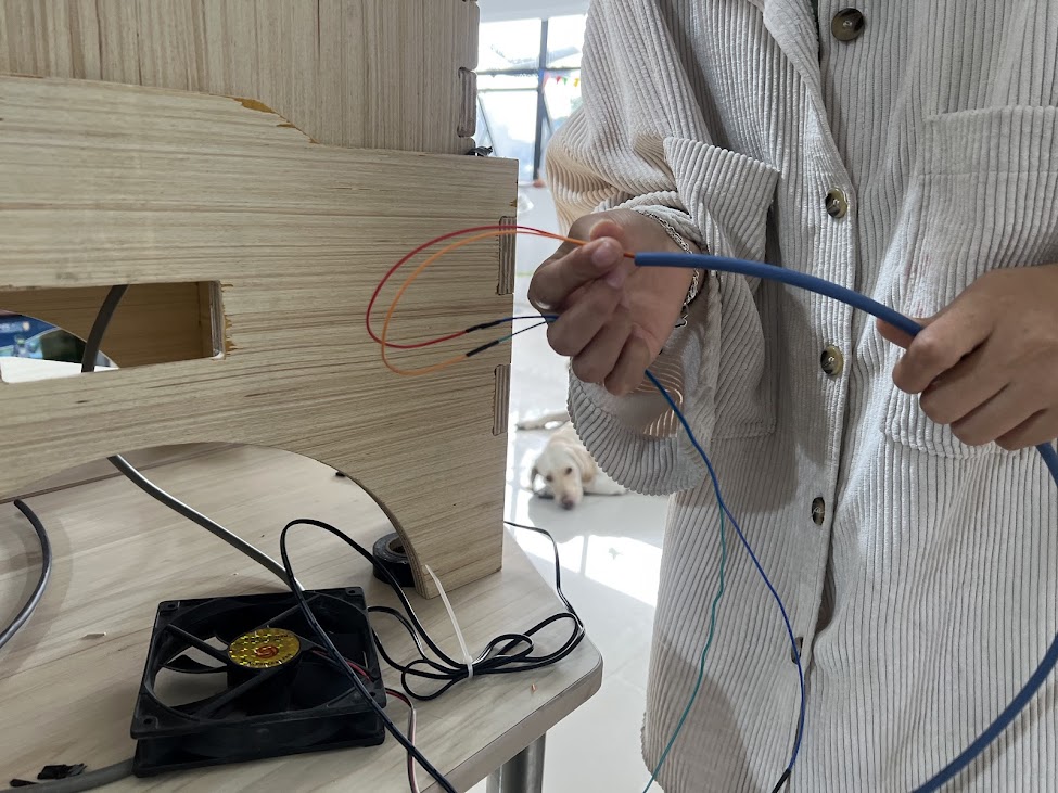
Here so that everything is more organized, place this Cable Wrap Organizer also called Spiral Tube, Serpentine, Threading Tube, Desktop Computer Accessories, everything was super organized.

Week 17.3D Applications and implications, project development
-
I leave you a link where I develop all the questions
- Propose a final project masterpiece that integrates the range of units covered, answering:
- What will it do?
- Who's done what beforehand?
- What will you design?
- What materials and components will be used?
- Where will come from?
- How much will they cost?
- What parts and systems will be made?
- What processes will be used?
- What questions need to be answered?
- How will it be evaluated?
- Your project should incorporate 2D and 3D design, additive and subtractive fabrication processes, electronics design and production, embedded microcontroller interfacing and programming, system integration and packaging
- Where possible, you should make rather than buy the parts of your project
- Projects can be separate or joint, but need to show individual mastery of the skills, and be independently operable
Week 18.3D Invention, intellectual property, and income
You can find this part here
Intellectual Property Considerations
Novelty and Non-Obviousness
- Ensure that the modular design and specific combination of components are novel and non-obvious.
- Define the scope of the invention clearly in the claims section, including the modular design, configurations of the modules, and the programming logic.
- Provide a comprehensive description of the invention, including technical specifications, assembly process, and programming logic.
- Highlight the practical applications and advantages of the invention
Manufacturing Processes:
The construction of the Dry Fruit system involves several manufacturing processes to ensure precision and functionality. The structure is designed in Fusion 360, with plans drafted in AutoCAD for CNC machining. The electronic circuit boards are designed and milled, followed by soldering the components. Laser cutting is employed to create divisions and specific parts of the structure, while 3D printing is used to fabricate supports for internal divisions. Vinyl cutting is used for logos and labels, adding a professional finish to the dryer. The assembled system includes a glass top for observation, providing both functionality and aesthetic appeal. These processes together contribute to the high-quality, efficient construction of the modular dryer.


