write a program for a microcontroller development board that you made,
to interact (with local input &/or output devices)
and communicate (with remote wired or wireless devices)
Extra credit: use different languages &/or development environments
Extra credit: connect external components to the board
Group assignment:
Browse through the data sheet for your microcontroller compare the performance and development workflows for other architectures
Let's start
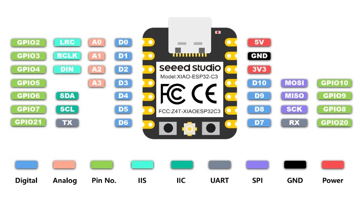
Seeed Studio XIAO Series are diminutive development boards, sharing a similar hardware structure, where the size is literally thumb-sized.
The code name "XIAO" here represents its half feature "Tiny", and the other half will be "Puissant".
Description
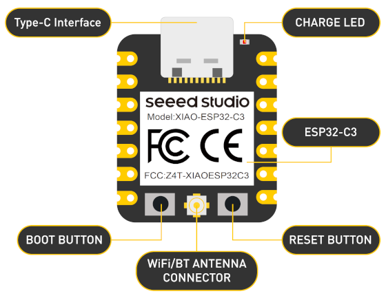
Seed Studio XIAO ESP32C3 has equipped a highly-integrated ESP32-C3 chip, built around a 32-bit RISC-V chip processor with a four-stage pipeline that operates at up to 160 MHz.
The board equips highly-integrated ESP32-C3 SoC. The chip has been installed with a complete 2.4GHz Wi-Fi subsystem which means it supports Station mode, SoftAP mode, SoftAP & Station mode,
and promiscuous mode for multiple Wi-Fi applications. It works under an ultra-low power state, also supporting features of Bluetooth 5 and Bluetooth mesh. There are 400 KB SRAM & 4 MB Flash on the chip,
allowing for more programming space, and bringing more possibilities to the IoT control scenarios.
Equipped with a cooling system, which will keep the water circulating through the laser tube at a stable temperature.
Being a number to the Seeed Studio XIAO family, the board deservedly maintains the classic thumb-sized form-factor design and elegant productization of single-sided components mounting.
Meanwhile, it has equipped with a battery charge chip and integrated circuit for enhancing its ability to carry. This board comes included with an external antenna to increase the signal strength for wireless applications.
There are 11 digital I/O that can be used as PWM pins and 4 analog i/o that can be used as ADC pins. It supports UART, IIC, and SPI serial communication ports.
Utilizing its small and exquisite hardware design and the powerful onboard chip, programming by Arduino, it will offer more ability to wearable and portable devices or other applications.
Application
Internet of Things
Wearable devices
Health monitoring
Education
Rapid prototyping
Specification
Parameter
Description
Processor
ESP32-C3 SoC
RISC-V single-core 32-bit chip processor with a four-stage pipeline that operates at up to 160 MHz
Seeed Studio XIAO ESP32C3 is an IoT mini development board based on the Espressif ESP32-C3 WiFi/Bluetooth dual-mode chip. ESP32-C3 is a 32-bit RISC-V CPU,
which includes an FPU (Floating Point Unit) for 32-bit single-precision arithmetic with powerful computing power. It has excellent radio frequency performance, supporting IEEE 802.11 b/g/n WiFi,
and Bluetooth 5
(LE) protocols. This board comes included with an external antenna to increase the signal strength for your wireless applications. It also has a small and exquisite form-factor combined with a single-sided surface-mountable design.
It is equipped with rich interfaces and has 11 digital I/O that can be used as PWM pins and 4 analog I/O that can be used as ADC pins. It supports four serial interfaces such as UART, I2C and SPI.
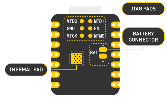
There is also a small reset button and a bootloader mode button on the board. XIAO ESP32C3 is fully compatible with the Grove Shield for Seeeduino XIAO and Seeeduino XIAO Expansion board except for the Seeeduino XIAO Expansion board, the SWD spring contacts on the board will not be compatible.
5V - This is 5v out from the USB port. You can also use this as a voltage input but you must have some sort of diode (schottky, signal, power) between your external power source and this pin with anode to battery, cathode to 5V pin.
3V3 - This is the regulated output from the onboard regulator. You can draw 700mA
GND - Power/data/signal ground
Programming Seeed Studio XIAO ESP32-C3 with Arduino
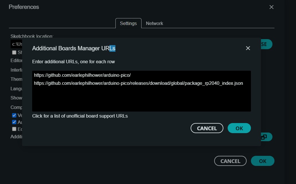
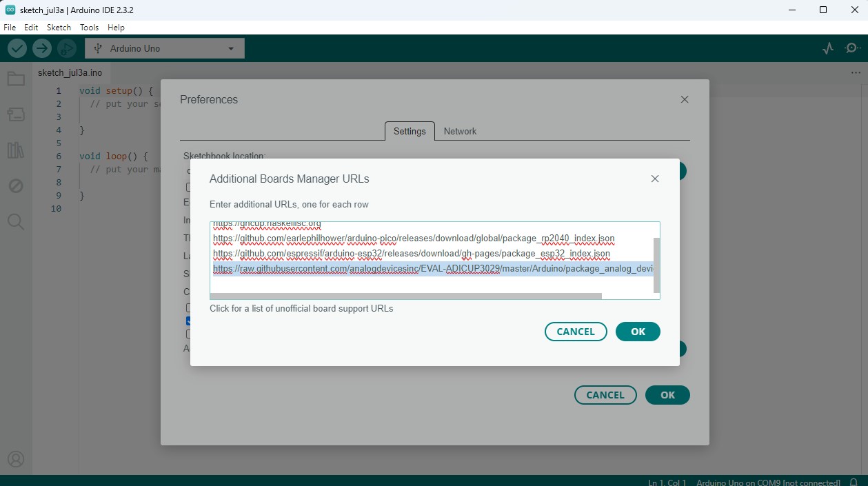
In the arduino menu bar the FILE/ Preferences path, we will add the URL of the additional boards that you can find here. We need the xiaoESP32c2.
File/preferences.click on the images
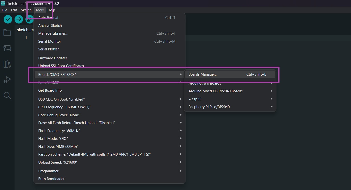
Tools/Board/Boards Manager.click on the images
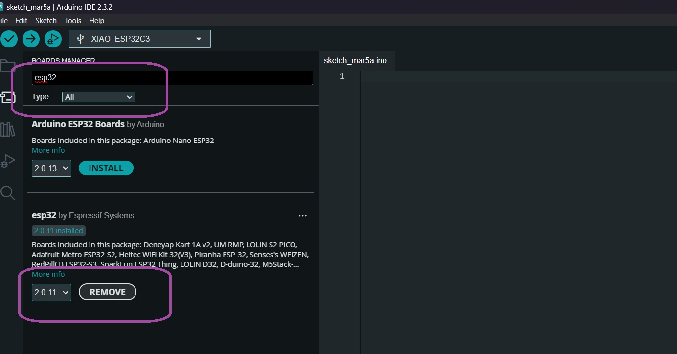
Library/Esp32 -> install .Click on the images
Now after placing the board that we are going to use, in my case the xiaoesp32c3, we are going to look for our board on board
File/preferences. Click on the images
Tools/Board/Boards Manager. Click on the images
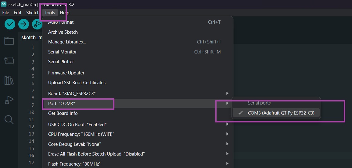
Place the COM port in my case it is COM3. Click on the images
Now load the Blink program so that the LED on pin D0 (GPIO 2) blinks.
Leds
							// Define the pins to which the lights are connected
							const int pinLed1 = 2;  // D2
							const int pinLed2 = 5;  // D5
							const int pinLed3 = 6;  // D6

							void setup() {
							// Configure the pins as outputs
							pinMode(pinLed1, OUTPUT);
							pinMode(pinLed2, OUTPUT);
							pinMode(pinLed3, OUTPUT);
							}

							void loop() {
							// Turn on the first light (pinLed1)
							digitalWrite(pinLed1, HIGH);
							delay(1000);  // Wait for 1 second

							// Turn off the first light
							digitalWrite(pinLed1, LOW);

							// Turn on the second light (pinLed2)
							digitalWrite(pinLed2, HIGH);
							delay(1000);  // Wait for 1 second

							// Turn off the second light
							digitalWrite(pinLed2, LOW);

							// Turn on the third light (pinLed3)
							digitalWrite(pinLed3, HIGH);
							delay(1000);  // Wait for 1 second

							// Turn off the third light
							digitalWrite(pinLed3, LOW);

							// Repeat the cycle
							}
The push button is the easiest and simplest element of the inputs. It is an open or closed contact that changes its state to closed or open when pressed.
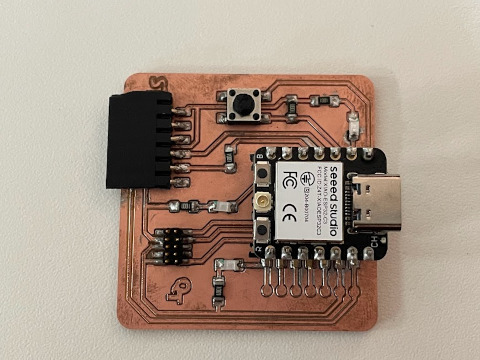
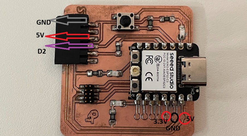
Connection and schematic
In this case for the XIAO ESP32C3, use la placa de quentorres the button is integrated , on the GPIO 4 pin (Arduino pin 2).
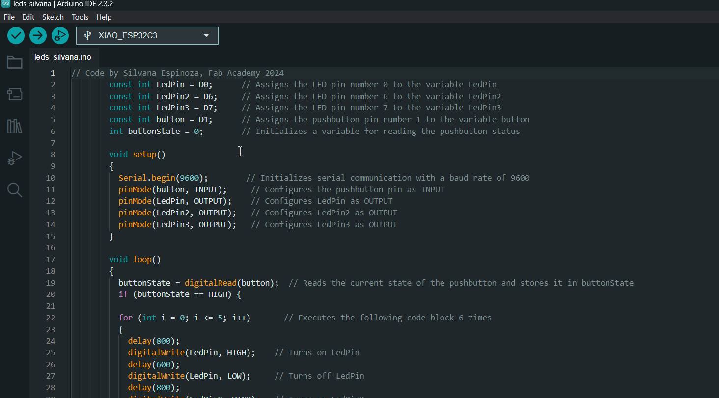
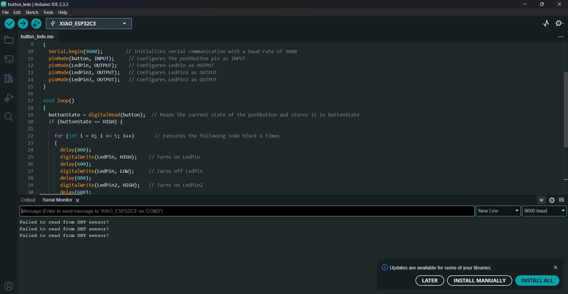
Button leds
				// Code by Silvana Espinoza, Fab Academy 2024
				const int LedPin = D0;      // Assigns the LED pin number 0 to the variable LedPin
				const int LedPin2 = D6;     // Assigns the LED pin number 6 to the variable LedPin2
				const int LedPin3 = D7;     // Assigns the LED pin number 7 to the variable LedPin3
				const int button = D1;      // Assigns the pushbutton pin number 1 to the variable button
				int buttonState = 0;        // Initializes a variable for reading the pushbutton status

				void setup()
				{
				  Serial.begin(9600);        // Initializes serial communication with a baud rate of 9600
				  pinMode(button, INPUT);     // Configures the pushbutton pin as INPUT
				  pinMode(LedPin, OUTPUT);    // Configures LedPin as OUTPUT
				  pinMode(LedPin2, OUTPUT);   // Configures LedPin2 as OUTPUT
				  pinMode(LedPin3, OUTPUT);   // Configures LedPin3 as OUTPUT
				}

				void loop()
				{
				  buttonState = digitalRead(button);  // Reads the current state of the pushbutton and stores it in buttonState
				  if (buttonState == HIGH) {

					for (int i = 0; i <= 5; i++)       // Executes the following code block 6 times
					{
					  delay(800);
					  digitalWrite(LedPin, HIGH);    // Turns on LedPin
					  delay(600);
					  digitalWrite(LedPin, LOW);     // Turns off LedPin
					  delay(800);
					  digitalWrite(LedPin2, HIGH);   // Turns on LedPin2
					  delay(600);
					  digitalWrite(LedPin2, LOW);    // Turns off LedPin2
					  delay(800);
					  digitalWrite(LedPin3, HIGH);   // Turns on LedPin3
					  delay(500);
					  digitalWrite(LedPin3, LOW);    // Turns off LedPin3
					}
				  } else {

					digitalWrite(LedPin, LOW);       // Turns off LedPin
					digitalWrite(LedPin2, LOW);      // Turns off LedPin2
					digitalWrite(LedPin3, HIGH);     // Turns on LedPin3
				  }
				}
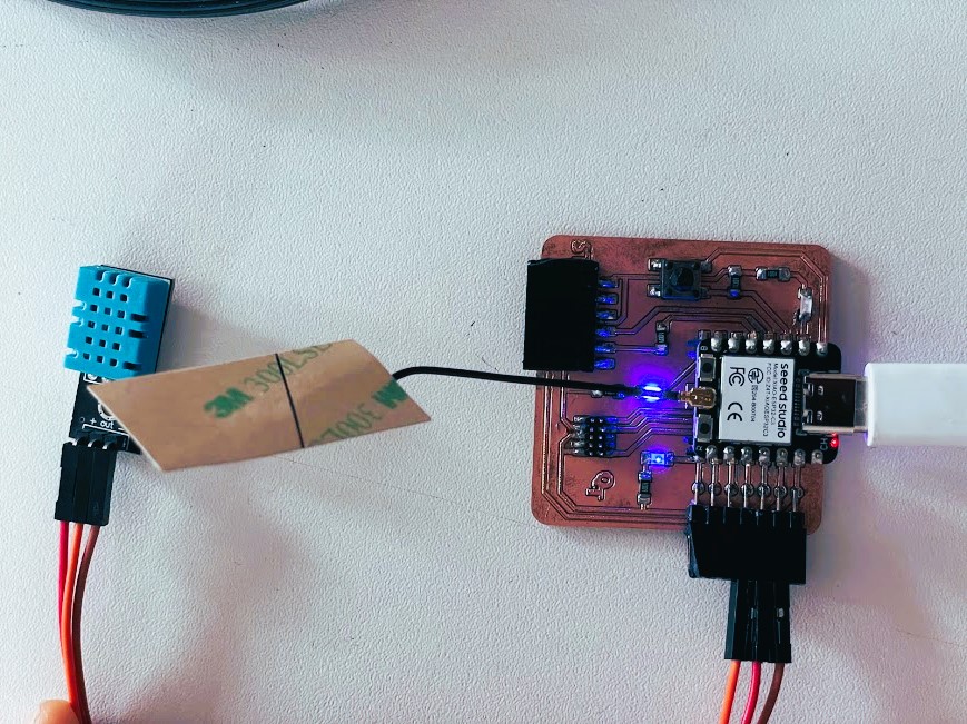
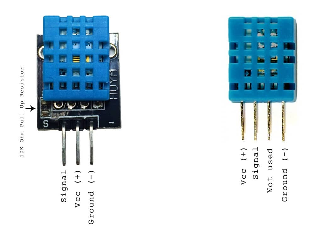
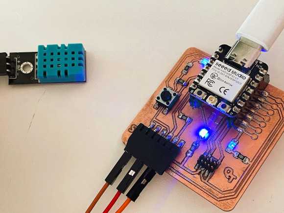
The program we are going to implement is the reading DHT11 Humidity & Temperature sensor data. Here is the connection diagram for this project.
Connect the DHT11 VCC
Connect the DHT11 GND
Connect the DHT11 pin to 3.3V
Source Code/Program
The code requires DHT11 Sensor Library for compilation (here I was delayed because I couldn't find the right one). So, first download and install the library using the library manager. Then copy the following code and upload it to the ESP32-C3 board.
Laser Focus Adjustment:
Make sure the work table is level.
Adjust the height of the table or laser to achieve optimum focus on the work material.
Checking and Adjusting Mirrors
Verify that the mirrors are clean and properly aligned.
Use a laser marker or laser pointer to ensure that the beam is properly reflected from each mirror to the cutting head.
Cutting Head Alignment
Align the cutting head so that it is perpendicular to the work surface.
Adjust any misalignment to ensure accurate cuts.
Power and Speed Calibration
Perform cutting tests on reference materials to adjust power and speed according to your needs and material type.
7mm gauge to use as a reference for laser cutting machine.
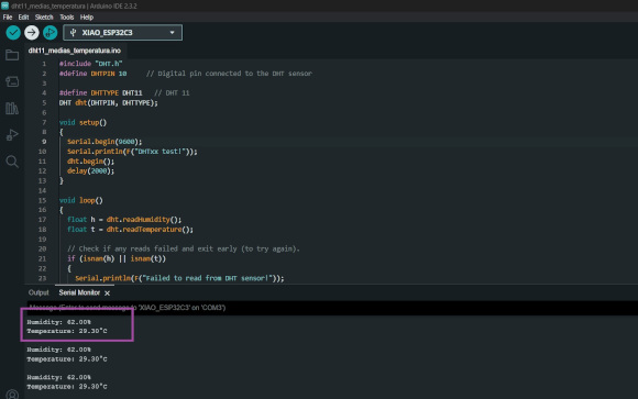
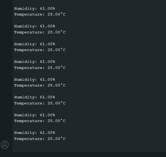
After uploading the code, open the Serial Monitor. The Serial Monitor will display the Humidity & Temperature Data.
Correctly arranging the MDF cutting material so that all sides
Button leds
					#include "DHT.h"
					#define DHTPIN 10     // Digital pin connected to the DHT sensor

					#define DHTTYPE DHT11   // DHT 11
					DHT dht(DHTPIN, DHTTYPE);

					void setup()
					{Serial.begin(9600);

						Serial.println(F("DHTxx test!"));
						dht.begin();
						delay(2000);
					}

					void loop()
					{
						float h = dht.readHumidity();
						float t = dht.readTemperature();

						 // Check if any reads failed and exit early (to try again).
						 if (isnan(h) || isnan(t))
					{
						Serial.println(F("Failed to read from DHT sensor!"));
						return;
					 }
						Serial.print(F("Humidity: "));
						Serial.print(h);
						Serial.println("%");
						Serial.print(F("Temperature: "));
						Serial.print(t);
						Serial.println(F("°C "));
						Serial.println("");
						delay(2000);
								}
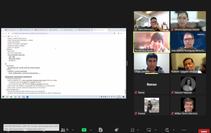
This week we were very united to do our homework for the week, I love my team.
Feb. 29
For this week we met with our evaluators and advisors who recommended the study of several microcontrollers,
they told us what we could investigate and with our classmates we organized ourselves to do the search and the
structure of the microcontrollers and to be able to study their architecture and characteristics. We decided that
each group could investigate a microcontroller and then be able to present it in a meeting so that everyone could
understand all the possible microcontrollers
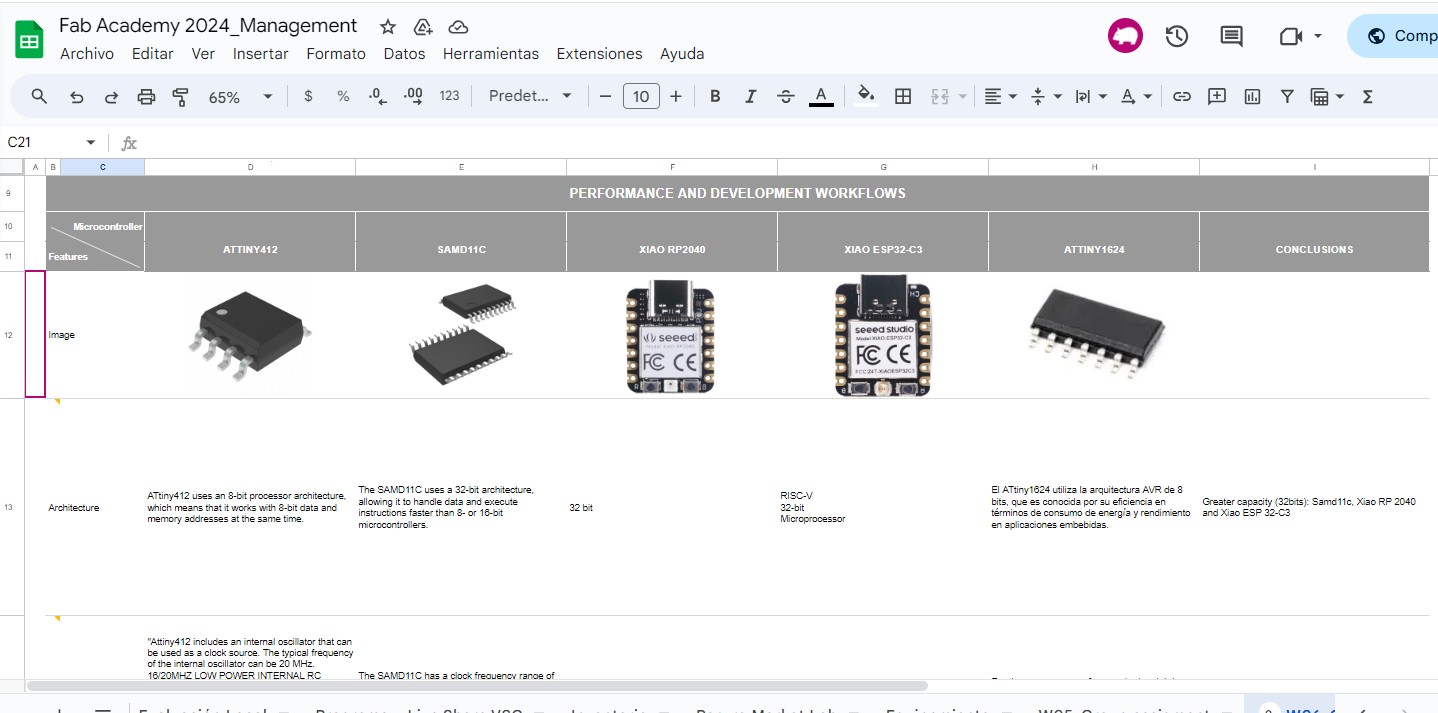
Datasheet Comparison for Diverse Architectures
we decided to work on a collaborative file in which we would compare various microcontrollers and their characteristics.
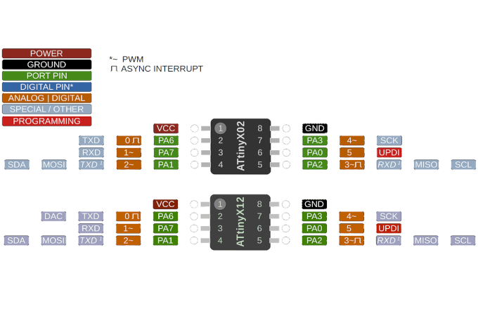
ATtiny412 uses an 8-bit processor architecture, which means that it works with 8-bit data and memory addresses at the same time.
The capacity of the Flash memory in the ATtiny412 is up to 4 kilobytes (KB). This means that it can store up to 4096 bytes of program code.
"The ATtiny412 is equipped with a variety of integrated peripherals that extend its capabilities and facilitate the implementation of various functions in embedded systems. Some of the integrated peripherals include timer/counters (TC), a PWM capture/comparison module (PWM), analog-to-digital converters (ADC), an event system (Event System), and a clock generator (CLK). The timers/counters are useful for measuring time intervals, the PWM module allows the generation of PWM signals to control motor speed and light intensity, the ADC facilitates the conversion of analog signals to digital for processing, the event system simplifies the interconnection between peripherals, and the clock generator allows adjusting the operating frequency.
Pins"
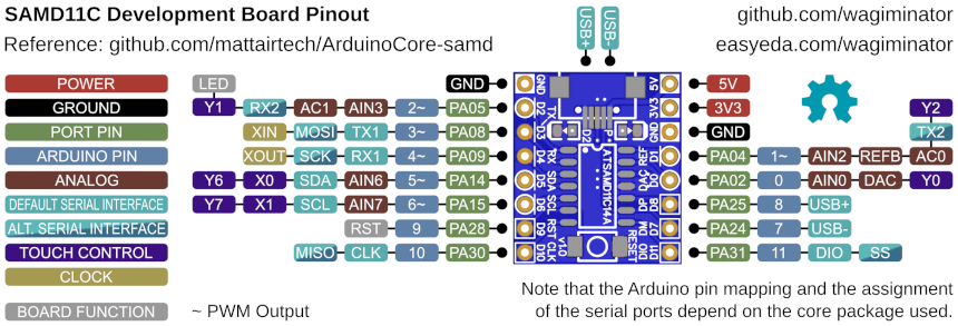
Architecture:The SAMD11C uses a 32-bit architecture, allowing it to handle data and execute instructions faster than 8- or 16-bit microcontrollers.
Clock frecuency:The SAMD11C has a clock frequency range of up to 48 MHz. This means it can operate at a clock speed of up to 48 million cycles per second.
Flash memory:The SAMD11C has flash memory of up to 16 KB. This means it can store up to 16,384 bytes of data or program instructions. Flash memory can be programmed using a microcontroller programmer or via a programming port built into the microcontroller
RAM memory:The SAMD11C has a RAM memory of up to 4 KB. This means that it can store up to 4,096 bytes of temporary or variable data while a program is running on the microcontroller.
Power consumption: "1.62 V a 3.63 V.
Compatibility with boards: SAM D11 Xplained Pro: Evaluation board with integrated peripherals.
ATSAMD11-XPRO: Evaluation board with integrated peripherals.
ATSAMD11G18A-XPRO: Evaluation board with integrated peripherals.
ATSAMD11D14AM-XPRO: Evaluation board with integrated peripherals.
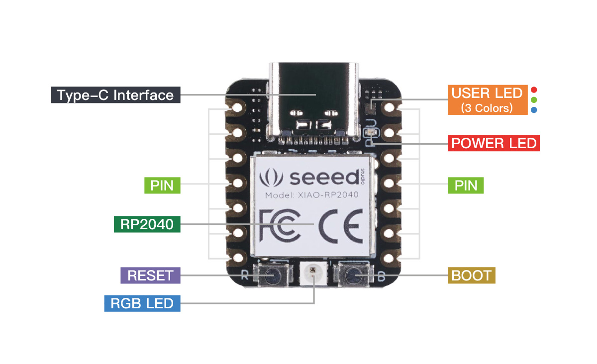
The Seeed Studio XIAO RP2040 is as small as the Seeed Studio XIAO SAMD21 but it's more powerful. On one hand, it carries the powerful Dual-core RP2040 processor that can flexible clock running up to 133 MHz which is a low-power microcontrollers. On the Seeed Studio XIAO RP2040 there is also 264KB of SRAM, and 2MB of on-board Flash memory which can provide more program to save and run. On the other hand, this little board has good performance in processing but needs less power.
There are 14 GPIO PINs on Seeed Studio XIAO RP2040, on which there are 11 digital pins, 4 analog pins, 11 PWM Pins,1 I2C interface, 1 UART interface, 1 SPI interface, 1 SWD Bonding pad interface.
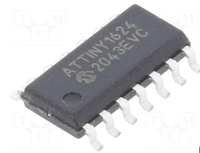
The ATtiny1624 is a microcontroller featuring the AVR® CPU with hardware multiplier, running at up to 20 MHz and with 16 KB Flash, 2 KB SRAM and 256B EEPROM in 14-pin TSSOP and SOIC packages. The family uses the latest Core Independent Peripherals with low-power features, including Event System, intelligent analog and advanced peripherals.
The ATtiny1624 uses the 8-bit AVR architecture, which is known for its efficiency in terms of power consumption and performance in embedded applications.
It can operate with a clock frequency of up to 20 MHz, which allows it to perform fast and efficient operations.
It has an integrated 16 KB Flash memory for program code storage. This allows for the implementation of medium to small applications on the microcontroller.
It has 512 bytes of SRAM memory for volatile data storage and 256 bytes of EEPROM memory for non-volatile data storage.
Supports various serial communication protocols, including UART, SPI and I2C, which facilitates communication with other devices and sensors
Architecture:The SAMD11C uses a 32-bit architecture, allowing it to handle data and execute instructions faster than 8- or 16-bit microcontrollers.
Clock frecuency:The SAMD11C has a clock frequency range of up to 48 MHz. This means it can operate at a clock speed of up to 48 million cycles per second.
Flash memory:The SAMD11C has flash memory of up to 16 KB. This means it can store up to 16,384 bytes of data or program instructions. Flash memory can be programmed using a microcontroller programmer or via a programming port built into the microcontroller
RAM memory:The SAMD11C has a RAM memory of up to 4 KB. This means that it can store up to 4,096 bytes of temporary or variable data while a program is running on the microcontroller.
Power consumption: "1.62 V a 3.63 V.
Compatibility with boards: SAM D11 Xplained Pro: Evaluation board with integrated peripherals.
ATSAMD11-XPRO: Evaluation board with integrated peripherals.
ATSAMD11G18A-XPRO: Evaluation board with integrated peripherals.
ATSAMD11D14AM-XPRO: Evaluation board with integrated peripherals.
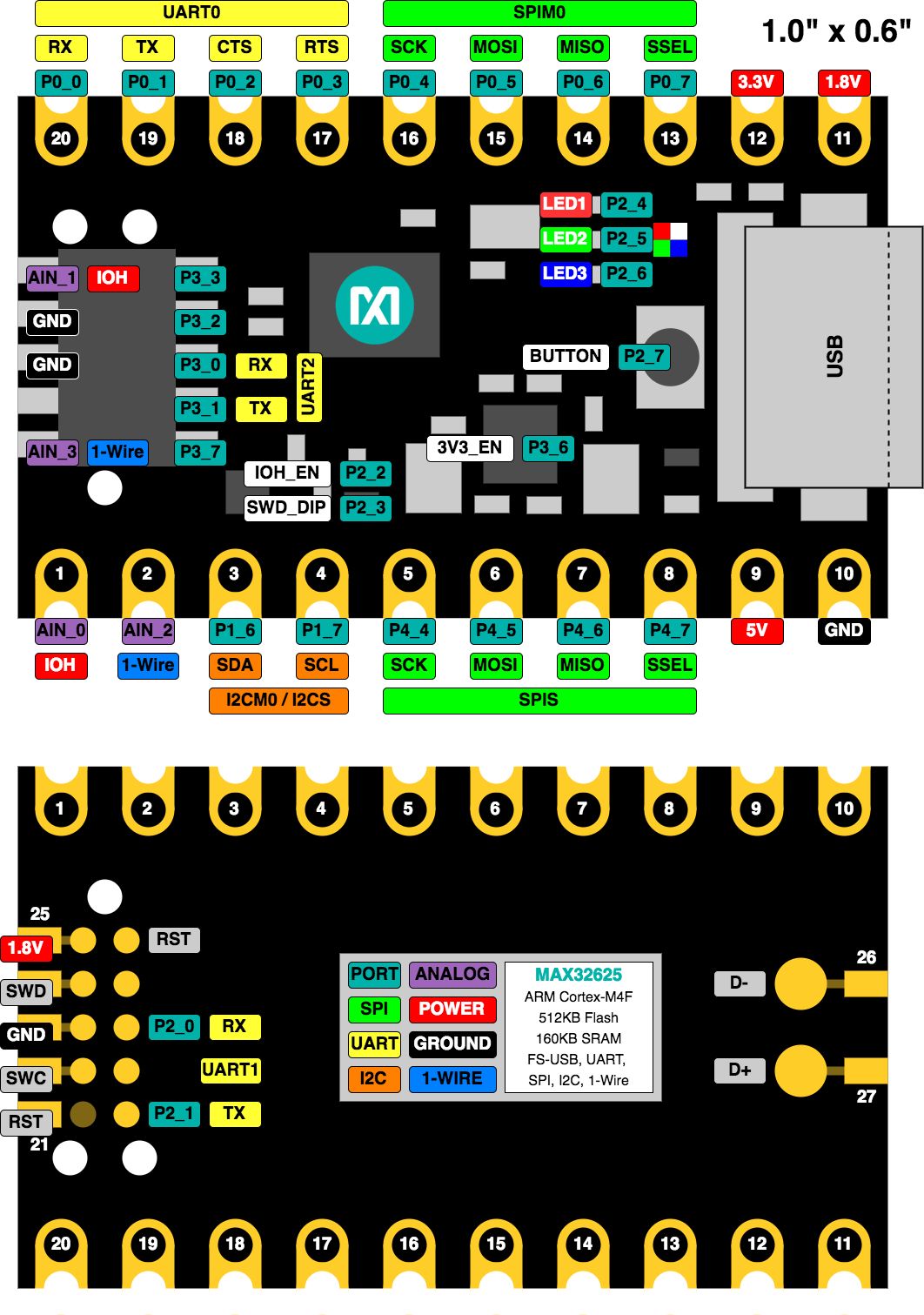
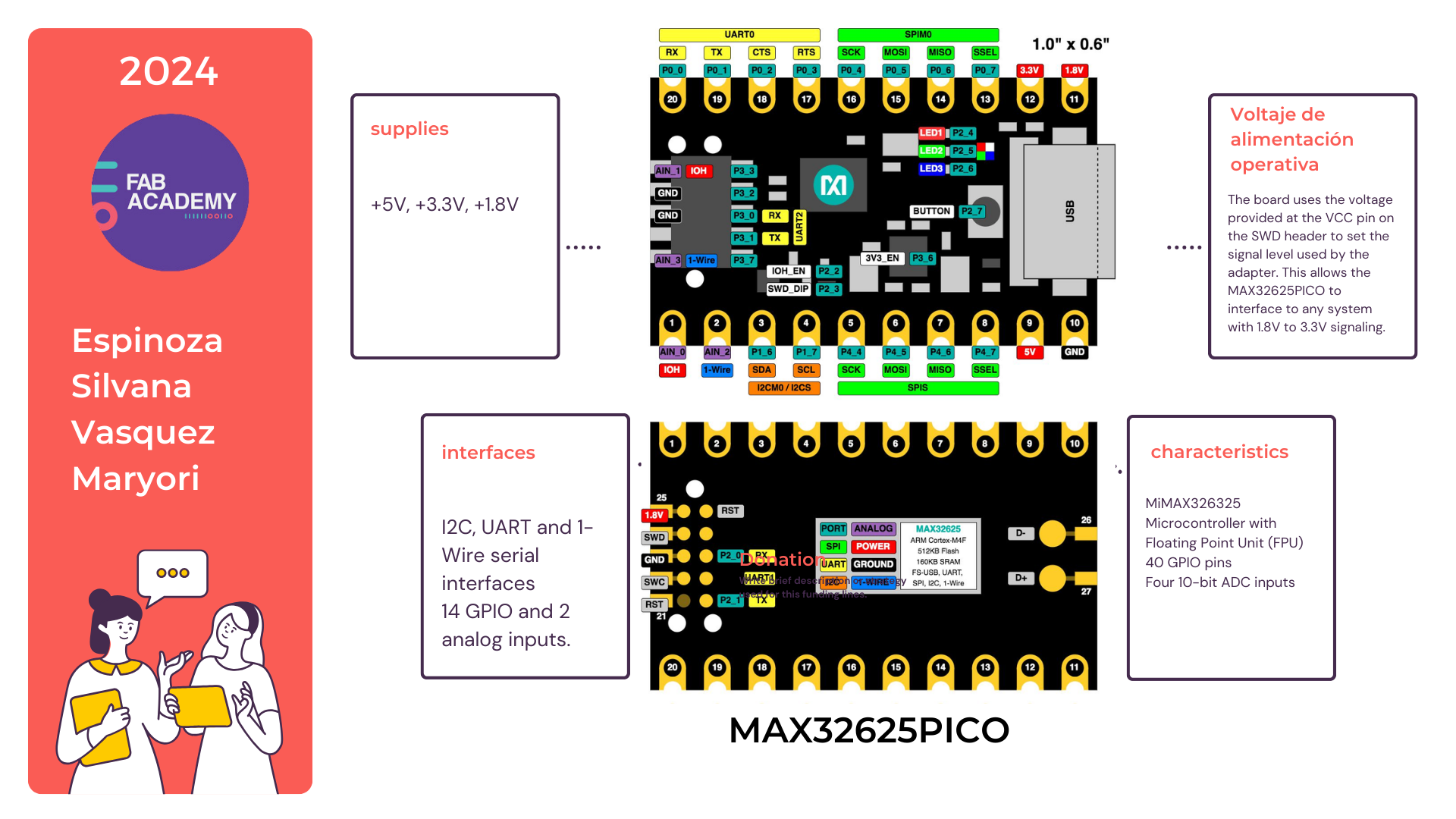
Max32625pico
Technical Characteristics of the MAX32625PICO Microcontroller:
Architecture: ARM Cortex-M4 with floating point unit (FPU)
Clock speed: Up to 96 MHz
Memory:
Flash: 512KB
RAM: 160KB
Communication interfaces:
UART: 3 ports
I²C: 3 ports
SPI: 3 ports
USB: Hi-Speed USB 2.0, compatible with USB OTG
GPIO:
36 general purpose input/output pins
Peripherals:
ADC: 10 12-bit channels
DAC: Not available
Timers: 6 32-bit timers
PWM: 16 PWM channels
Operating voltage: 1.7V to 3.6V
Low Power Mode: Includes power saving modes
Debug: JTAG and SWD (Serial Wire Debug)
Crypto: Cryptographic accelerator with support for AES, RSA, ECC, SHA-2
RTC: Real time clock with battery backup support
Security: Secure Boot, Memory Protection Unit (MPU)
Comparative Table of Programming Languages: Arduino IDE vs Mbed OS
May require additional tools, but supports USB, JTAG, SWD
Community and Support
Huge community, lots of support
Strong support from ARM and partners, good documentation
Flexibility and Scalability
Suitable for small to medium projects
Excellent for projects of any scale
Memory and Resource Management
Manual, often less efficient
Automated and efficient
OTA Updates
Limited, requires custom setup
Well supported, especially on ARM platforms
License
Free (open-source)
Free (open-source), with licensed components
Tool Ecosystem
Limited to Arduino and some external tools
Extensive, with integration to ARM and third-party tools
Additional Details
Development Speed:
Arduino IDE: Ideal for quick projects and simple prototypes. The simplicity of its environment and the wide availability of examples and libraries make initial development very fast.
development very fast.
Mbed OS: Allows for rapid development but is more suited for complex projects that require precise control and optimization. Initial setup can be slower due to the need to configure the environment.
Ease of Use:
Arduino IDE: Very beginner-friendly, with a smooth learning curve/li>
Mbed OS: Requires intermediate knowledge of programming and development environments. The documentation is excellent and detailed, making it easier for more advanced users to learn.
Development Environment:
Arduino IDE: A simplified environment that provides the basic tools needed for programming and code uploading.
Mbed OS: Offers multiple development options, such as Mbed Studio (full IDE), Mbed Online Compiler (online compiler), and Mbed CLI (command-line tools).
Code Uploading:
Arduino IDE: Code uploading is straightforward through the USB port, simplifying the programming process.
Mbed OS: May require additional tools for code uploading but offers support for multiple programming interfaces, including JTAG and SWD.
Debugging
Arduino IDE: Mainly serial debugging, suitable for basic debugging.
Mbed OS: Supports advanced debugging with hardware-level access, allowing for deeper inspection of code and hardware behavior.
Memory and Resource Management:
Arduino IDE: Memory management is manual and can be less efficient, depending on the programmer's skills.
Mbed OS: Offers automated and efficient resource management, optimized for low-power and high-performance applications.
Conclusion
The choice between Arduino IDE and Mbed OS for programming the MAX32625PICO depends on the user's experience level and the project's complexity:
Arduino IDE is ideal for beginners and quick or simple projects.
Mbed OS is more suitable for users with intermediate to advanced experience and for more complex projects that require precise control and optimization.
Both environments have their strengths and are widely used in the microcontroller development community.
Comparative Table: XIAO RP2040 vs MAX32625PICO
Comparative Table: XIAO RP2040 vs MAX32625PICO
Aspect
XIAO RP2040
MAX32625PICO
Processor
Dual-core Arm Cortex-M0+ @ 133MHz
Arm Cortex-M4 @ 96MHz
Flash Memory
2MB
512KB
RAM
264KB
160KB
GPIO Pins
11
34
ADC Channels
4
8
Interfaces
UART, I2C, SPI
UART, I2C, SPI, USB, CAN
USB
Micro USB
Micro USB
Operating Voltage
3.3V
3.3V
Power Consumption
Low
Ultra-Low
Size
21 x 17.5 mm
25 x 7.6 mm
Programming Languages
MicroPython, C/C++ (Arduino)
C/C++ (Mbed)
Development Environment
Arduino IDE, Thonny, VS Code
Mbed Studio, Mbed Online Compiler
Price
Low
Moderate
/* mbed Microcontroller Library
 * Copyright (c) 2019 ARM Limited
 * SPDX-License-Identifier: Apache-2.0
 */


#include "mbed.h"


// Blinking rate in milliseconds
#define BLINKING_RATE     500ms


int main()
{
    // Initialise the digital pin LED1 as an output
#ifdef LED1
    DigitalOut led(LED1);
#else
    bool led;
#endif


    while (true) {
        led = !led;
        ThisThread::sleep_for(BLINKING_RATE);
    }
}
Tutorial
https://www.youtube.com/watch?v=AlJ3JALnJ2c
The step by step
We explore to program in Arduino IDE.
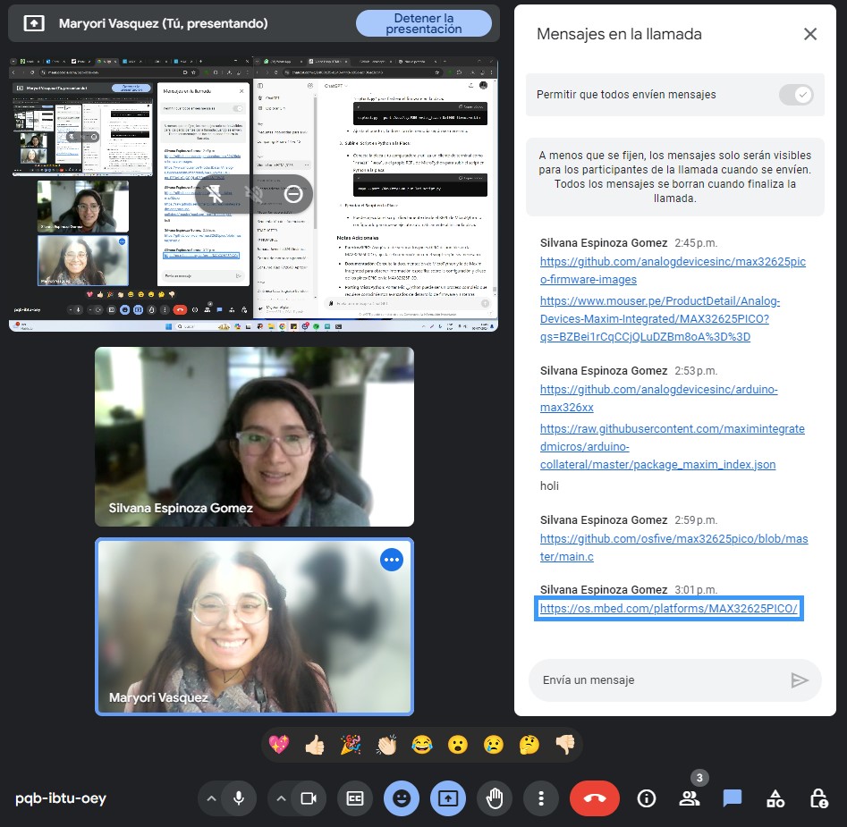
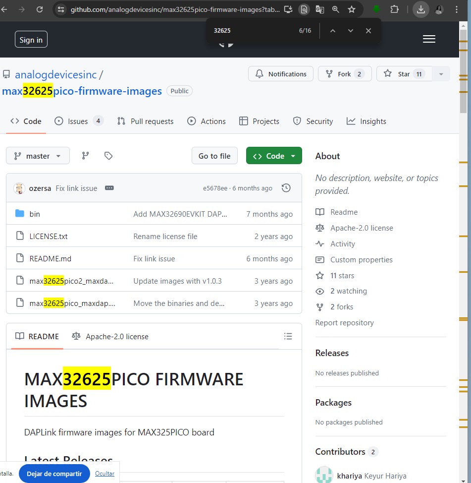
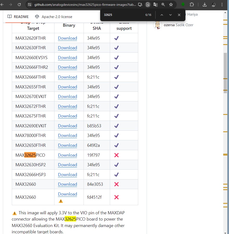
First we copy the links that we found in a repository to be able to work with this Max32625pico microcontroller
Here we were downloading it
we located it
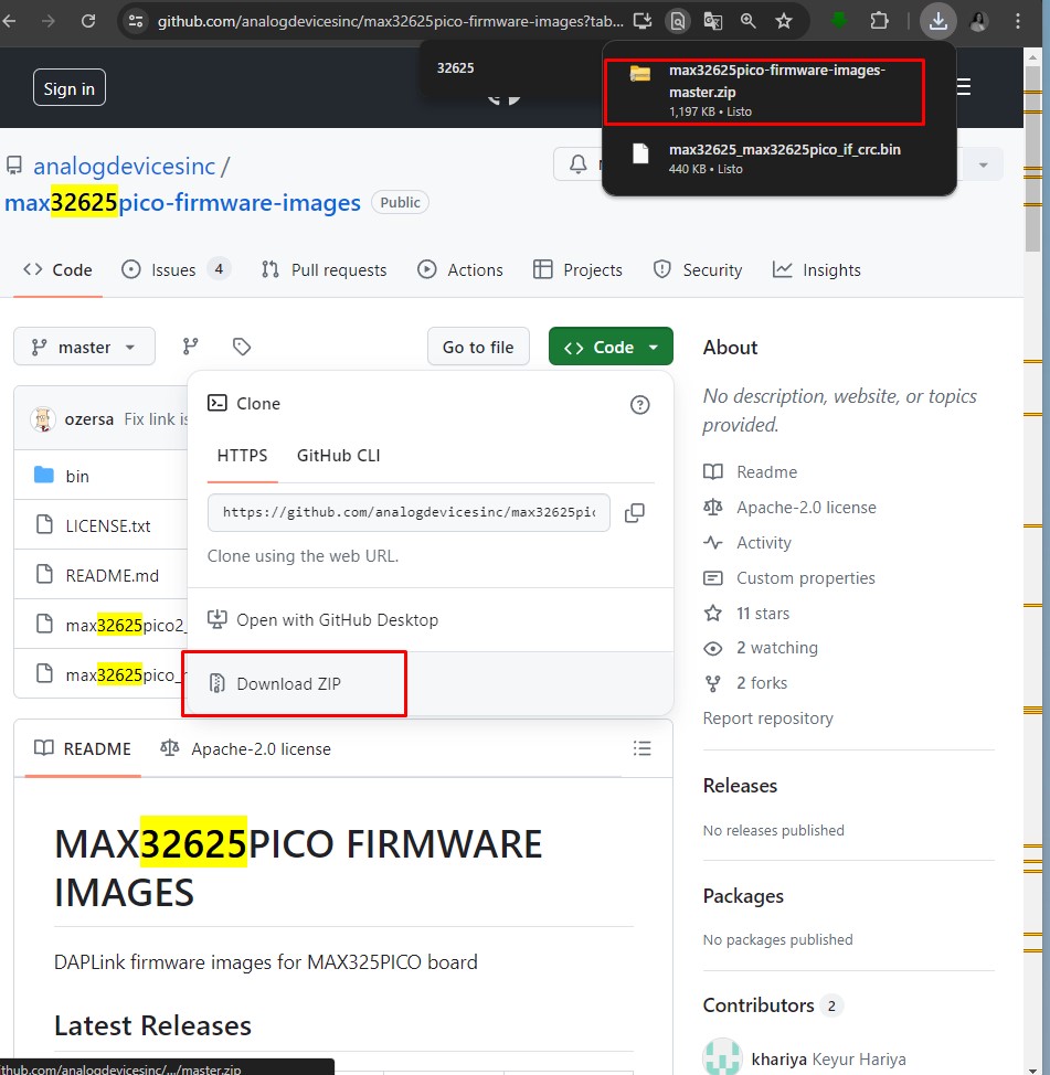
The step by step
and then download the ZIP
guess!
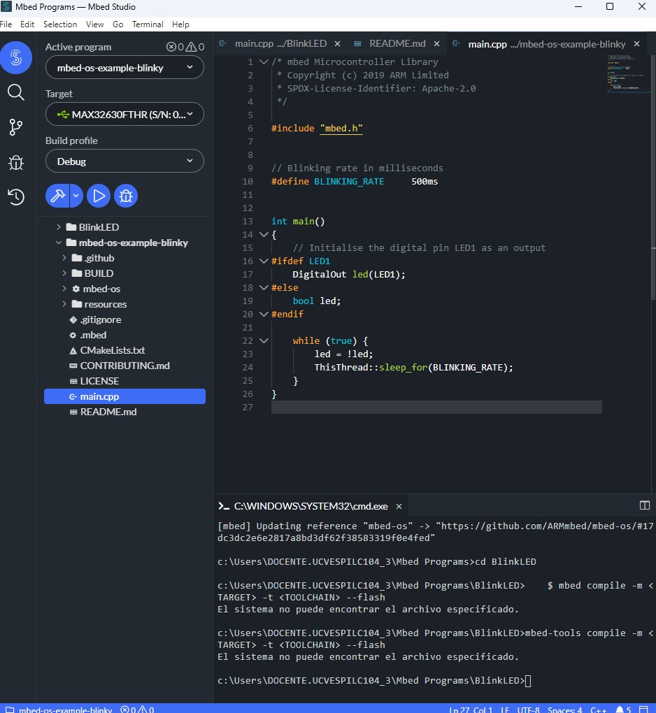
It didn't work, we couldn't locate the board, we took an hour until we investigated and saw that it could be done with mbed.
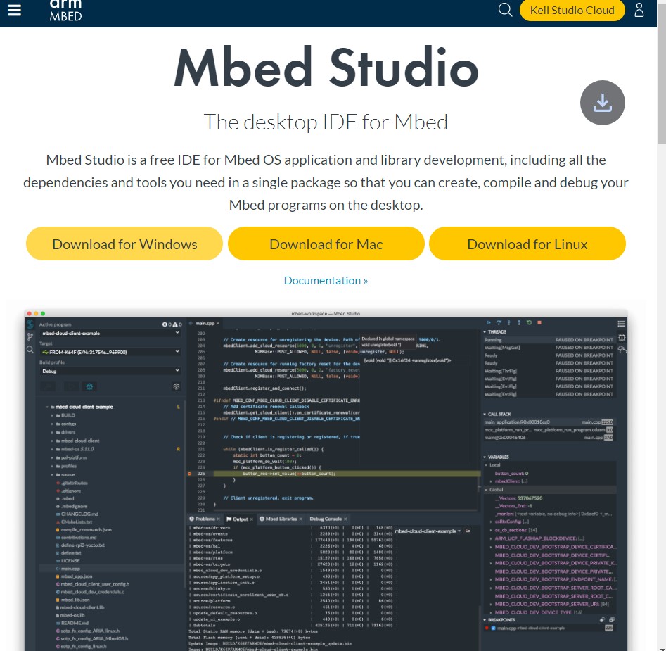
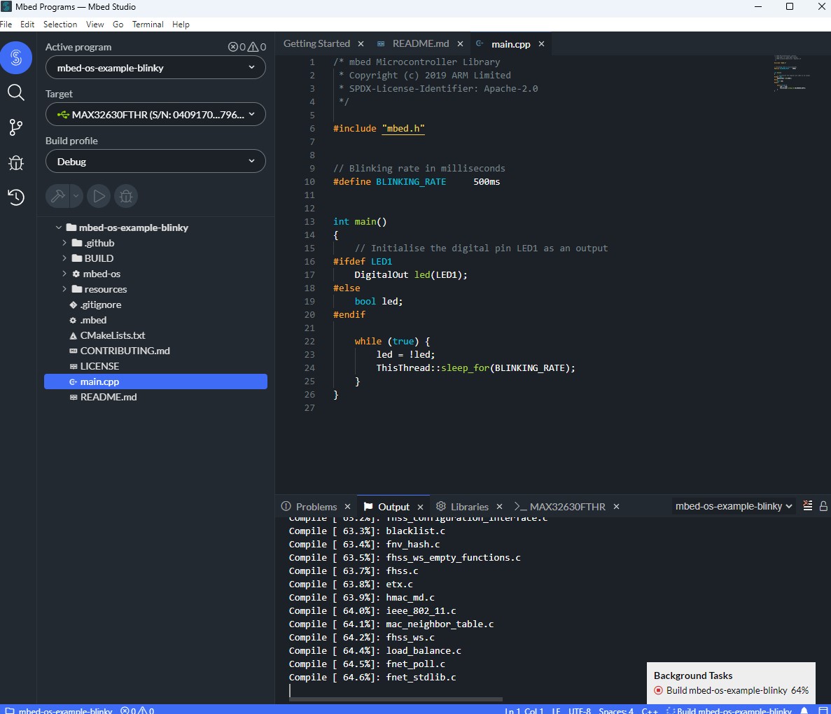
Here with mbed we have to download the program, maryori and I start downloading it
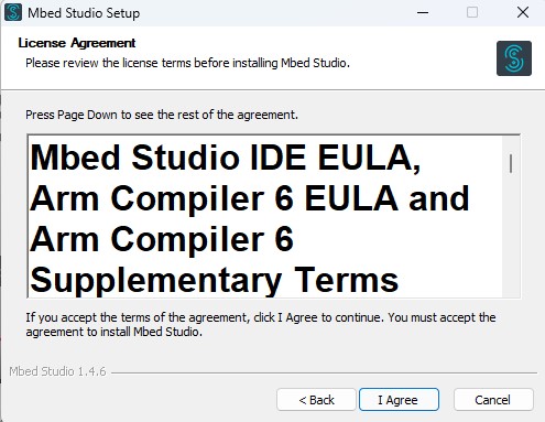
we install mbed studio
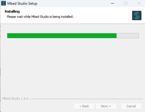
We see how it is being installed
We wait, the good thing is that it didn't take long to download it, it was fast.
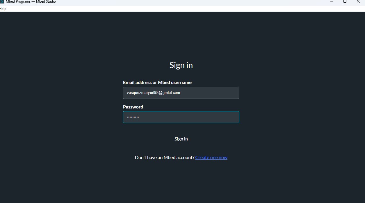
Here Maryori already created an account to be able to enter Mbed, interesting that the platform is very similar to visual studio code,
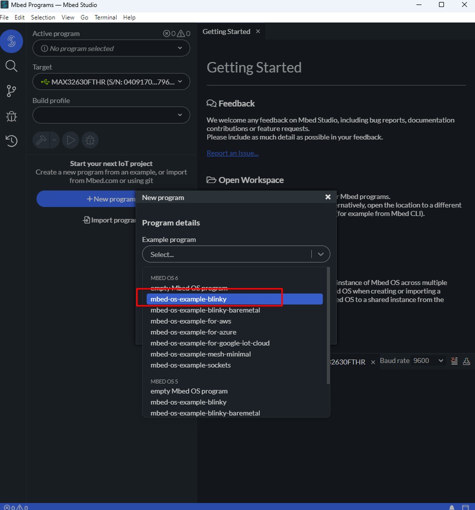
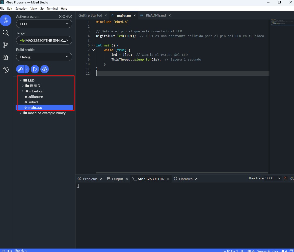
Here it was intuitive to be able to select the board when we connect it it appears
We saw the programs that it has loaded and we programmed to turn on an internal LED that the board has, here in these two photos you can see the step by step
Doing connection tests everything worked very well and turned on, we were very happy
The errors I had were in the tracks of my board which some were not well soldered so I had to make another one which turned out very well and I could continue with the practice.
At the beginning I didn't light up a led and I was testing with the multimeter to see which track was the one that was failing and I found it and I could solve it.
You have to keep in mind and the sensor libraries you are going to use I couldn't find the right one and that's why I get errors all the time.
What went well
I tried to place a temperature and humidity sensor and managed to connect it correctly so that it can measure the ambient temperature and humidity.
The programming code for the LEDs came out very well and I was very excited.
What I would do difherently
What I would do differently is research the microcontroller I am going to use more than what I had already read and seen.
I would document everything at the beginning because then it gets a little tedious documenting in all the time don't leave it to the last.


 (LE) protocols. This board comes included with an external antenna to increase the signal strength for your wireless applications. It also has a small and exquisite form-factor combined with a single-sided surface-mountable design.
It is equipped with rich interfaces and has 11 digital I/O that can be used as PWM pins and 4 analog I/O that can be used as ADC pins. It supports four serial interfaces such as UART, I2C and SPI.
There is also a small reset button and a bootloader mode button on the board. XIAO ESP32C3 is fully compatible with the Grove Shield for Seeeduino XIAO and Seeeduino XIAO Expansion board except for the Seeeduino XIAO Expansion board, the SWD spring contacts on the board will not be compatible.
(LE) protocols. This board comes included with an external antenna to increase the signal strength for your wireless applications. It also has a small and exquisite form-factor combined with a single-sided surface-mountable design.
It is equipped with rich interfaces and has 11 digital I/O that can be used as PWM pins and 4 analog I/O that can be used as ADC pins. It supports four serial interfaces such as UART, I2C and SPI.
There is also a small reset button and a bootloader mode button on the board. XIAO ESP32C3 is fully compatible with the Grove Shield for Seeeduino XIAO and Seeeduino XIAO Expansion board except for the Seeeduino XIAO Expansion board, the SWD spring contacts on the board will not be compatible.