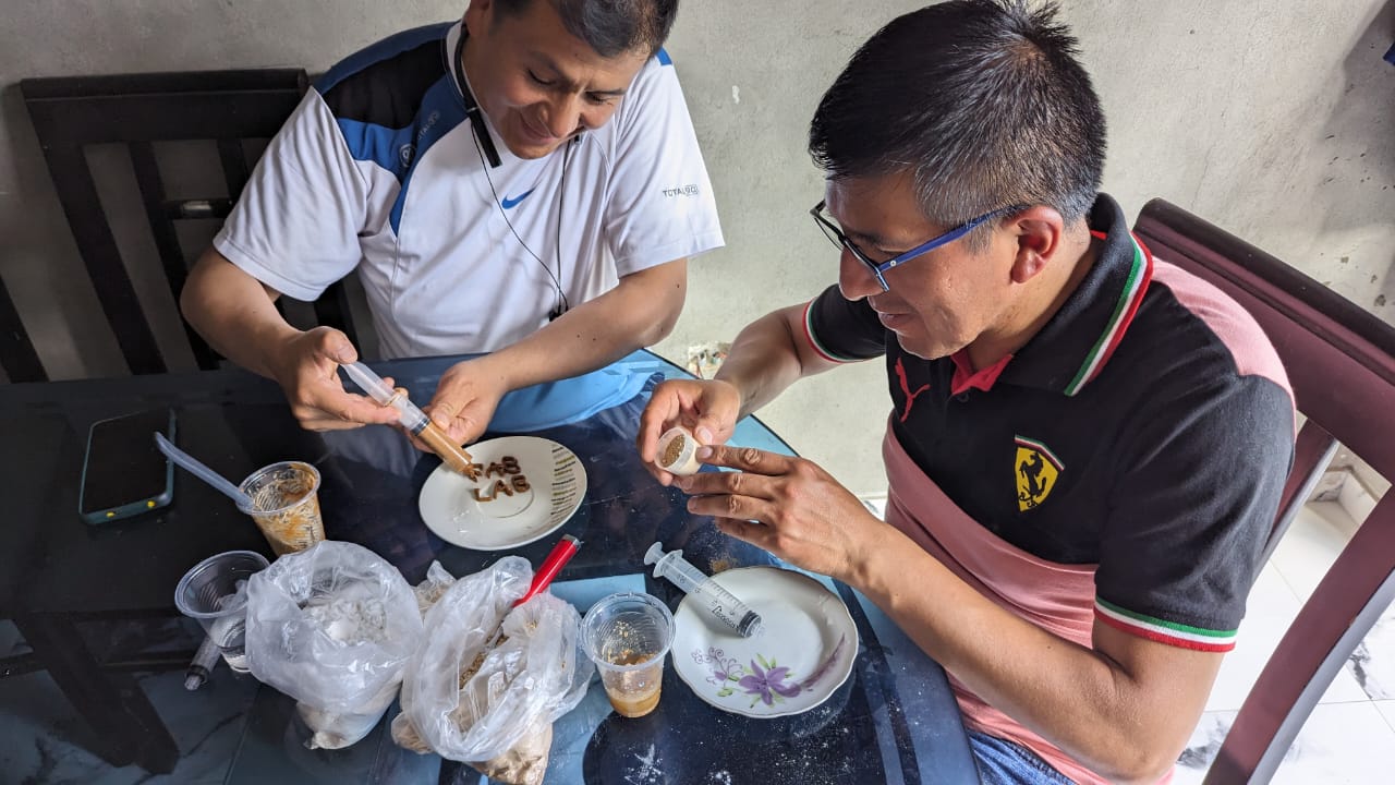
Today we began the exciting process of manufacturing our innovative printing machine for maca and copoazu candy. With the goal of bringing the unique flavors of the Peruvian jungle to the world, we embarked on this technical and creative challenge.
MACHINE WEEK GROUP
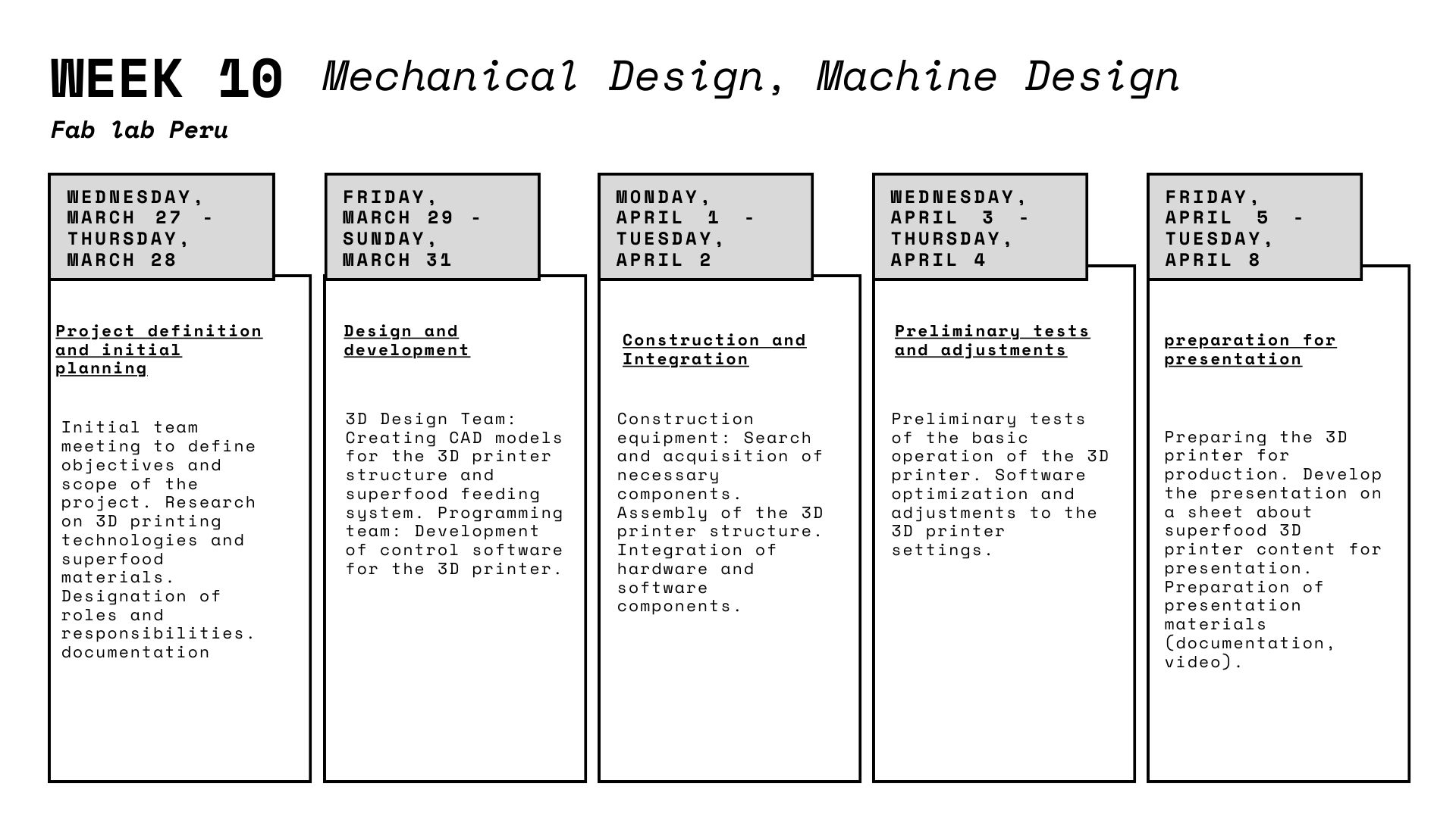
Design and Planning
Prototype Construction
Adjustments and Optimization
Biomaterials testing
Testing and Calibration
Conclusions
Group assignment:
Actuate and automate your machine
Document the group project and your individual contribution
Lima-Huanuco-Cerro de Pasco
Design and Planning
Name
"Pachamama" is a term that comes from the Quechua language, spoken primarily in the Andes of South America,
including regions of Peru, Bolivia, Ecuador, and parts of Colombia, Argentina and Chile. In the Andean cosmovision,
"Pachamama" refers to Mother Earth or Mother Nature. It is a deity or spiritual force revered by many indigenous
cultures of the Andean region.
The word "Pachamama" is composed of two Quechua terms: "Pacha", which means "earth" or "world", and "Mama", which means "mother".
Therefore, as a whole, "Pachamama" represents the idea of the Earth as a living and sacred entity, which provides life, sustenance
and protection to all beings that inhabit it. In Andean cultures, she is worshipped and respected through various ceremonies and rituals,
expressing gratitude and reverence for her generosity and care.
Lima-Huanuco-Cerro de Pasco

Team

Ronal Vilca
Industrial engineer

Renso
Ing. Systems

Wilber Giron
Computing and Informatic
Prototype Construction
We began the exciting task of manufacturing a machine.
For this activity, María, Ángela and I moved to Huánuco, which is approximately 10 hours from Lima,
with the purpose of working as a team with Ronald, Renso and Wilmer. Together, we brought the materials
and supplies necessary to build the machine we had previously designed. In addition, Franco accompanied
us on the trip and helped us with the acrylic necessary for the machine's casing.
Material
- 2 M8 Z axis threaded rods
- 3 Nut T8
- V-SLOT PROFILE 20X20x300
- 2 GT2 timing belt half meter 6mmx1M X and Y axis
- 2 GT2 toothed pulley 22 teeth M5 motor for the X and Y axis
- 2 GT2 22 smooth toothed pulley M5 X and Y axis
- 6 smooth M8 rods of 30 cm Y, Z and X axis
- Working temperature: -30ºC ~ 70ºC
- 10 M8 linear bearings
- 1 M8 threaded rod for the extruder
- 8 90 degree angles per 20 mm
- 3 Flexible couplings M5xM8
- 1 Flexible coupling M8xM8 15 soles
Nuts and bolts
- 100 SLIDING HAMMER HEAD NUT M5 (order more, they will be lost)
- 40 M3 engine bolts
- 100 M5 screws
Electronic
- Arduino Mega
- 3D Printer Controller Board RAMPS 1.4 Arduino Mega Shield
- 5 Stepper motor NEMA 17 42x39mm 4.2Kg
- 2 100k thermistors (to see the temperature at which material is worked in the environment)
- 1 Lcd Graphic 128x64 Shield Ramps 1.4 3d Printer
- 5 Cable for stepper motor, 1 meter long, 4 wires, with HX254 Female
- Inputs for motor (Nema 17)
- 12V and 20A power supply with power cable
- 3 Limit Switch Module for 3D Printer
- A4988 Stepper Motor Driver Module for Pololu
In preparation for week 10 of the FAb Academy, we embarked on an exciting building project: creating a machine from scratch using recycled parts from a Delta Kossel Linear Plus – Anycubic printer. This machine will be the center of our work during this crucial stage of the FAb Academy.
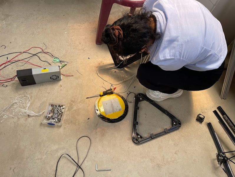
Upon identifying that the printer's rods and motors were in usable condition, we decided to disassemble it to rescue these valuable components. Although some of the parts were slightly rusty, we spent time cleaning them meticulously to ensure they function optimally on our project.
Once the printer was disassembled, we made an exhaustive list of the materials needed to build our machine. Fortunately, we had the contribution of Ronald, who had some essential drivers and motors for our setup.
However, during planning, we realized that we were missing some key rods to complete the desired structure. This discovery made us reflect on the need to streamline our processes, since time was short to meet the deadlines established by the FAb Academy.
Unfortunately, our progress was interrupted by an unexpected obstacle: the holiday, which closed the doors of hardware stores and prevented us from acquiring the missing materials. This setback reminded us of the importance of careful planning and motivated us to redouble our efforts to ensure the success of our project in week 10 of the FAb Academy
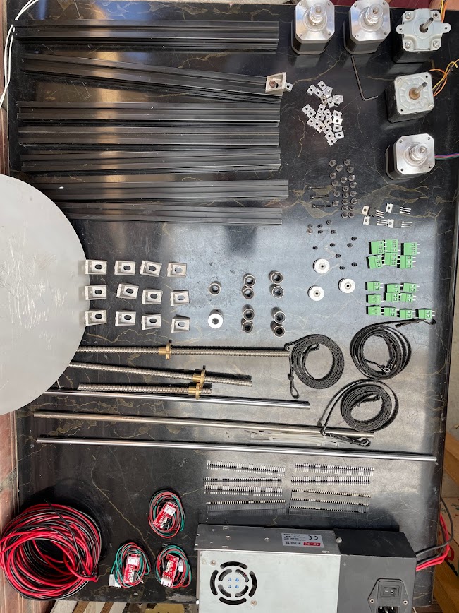
Here is the list of the components we need to assemble our pachamamprint.
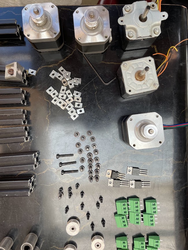
We need 5 nema 17 motors that we recovered, 3 from the 3D printer that we recycled and two that Ronald had from other recycled printers.
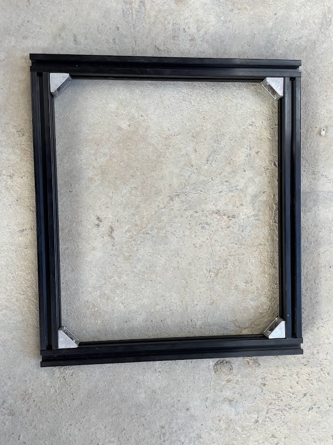
I collaborated with Ronald in the development of the 3D printer frame, making sure that all the details fit perfectly. From day one, I acted as his assistant as we evaluated the parts needed and designed the structure and system required for our machine. We worked together to analyze every aspect, ensuring that our project was based on a solid foundation to withstand movement and that the extrusion system was well planned. Of course, every day changed everything we had thought of at the beginning.
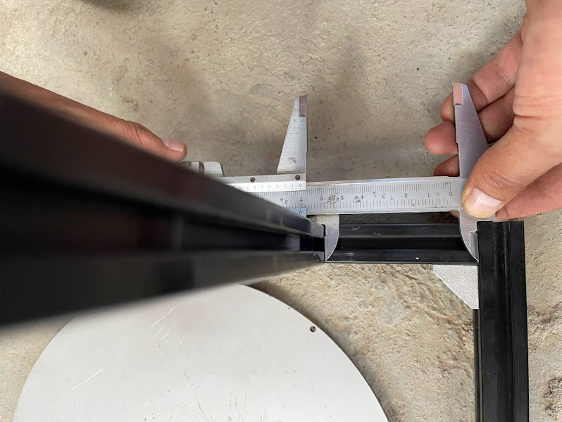
We took measurements of the distance where we need the Y axis to be and then we saw the height for the Z axis, which was where we initially had some problems due to the size of the extruder, but with the tests and the designs and redesigns that we did we managed to make a good base with changing extruder.
After adjusting the values in the Mill Raster 2D setup, I proceeded to perform the calculation to obtain the updated results. By editing these values, I was able to refine the milling parameters and obtain a more accurate and efficient machining process. This modification in the configuration allowed me to better adapt the milling strategy to the specific needs of my project, thus improving the quality and accuracy of the final result.
After adjusting the values in the Mill Raster 2D setup, I proceeded to perform the calculation to obtain the updated results. By editing these values, I was able to refine the milling parameters and obtain a more accurate and efficient machining process. This modification in the configuration allowed me to better adapt the milling strategy to the specific needs of my project, thus improving the quality and accuracy of the final result.

After adjusting the values in the Mill Raster 2D setup, I proceeded to perform the calculation to obtain the updated results. By editing these values, I was able to refine the milling parameters and obtain a more accurate and efficient machining process. This modification in the configuration allowed me to better adapt the milling strategy to the specific needs of my project, thus improving the quality and accuracy of the final result.

Program
I was in charge of seeing the programming to analyze and be able to calibrate correctly, with this process Ronald helped me understand how it works, and what programming line I have to modify so that the machine has an improvement with respect to the calibration and execution of the file to be placed.
Program 1
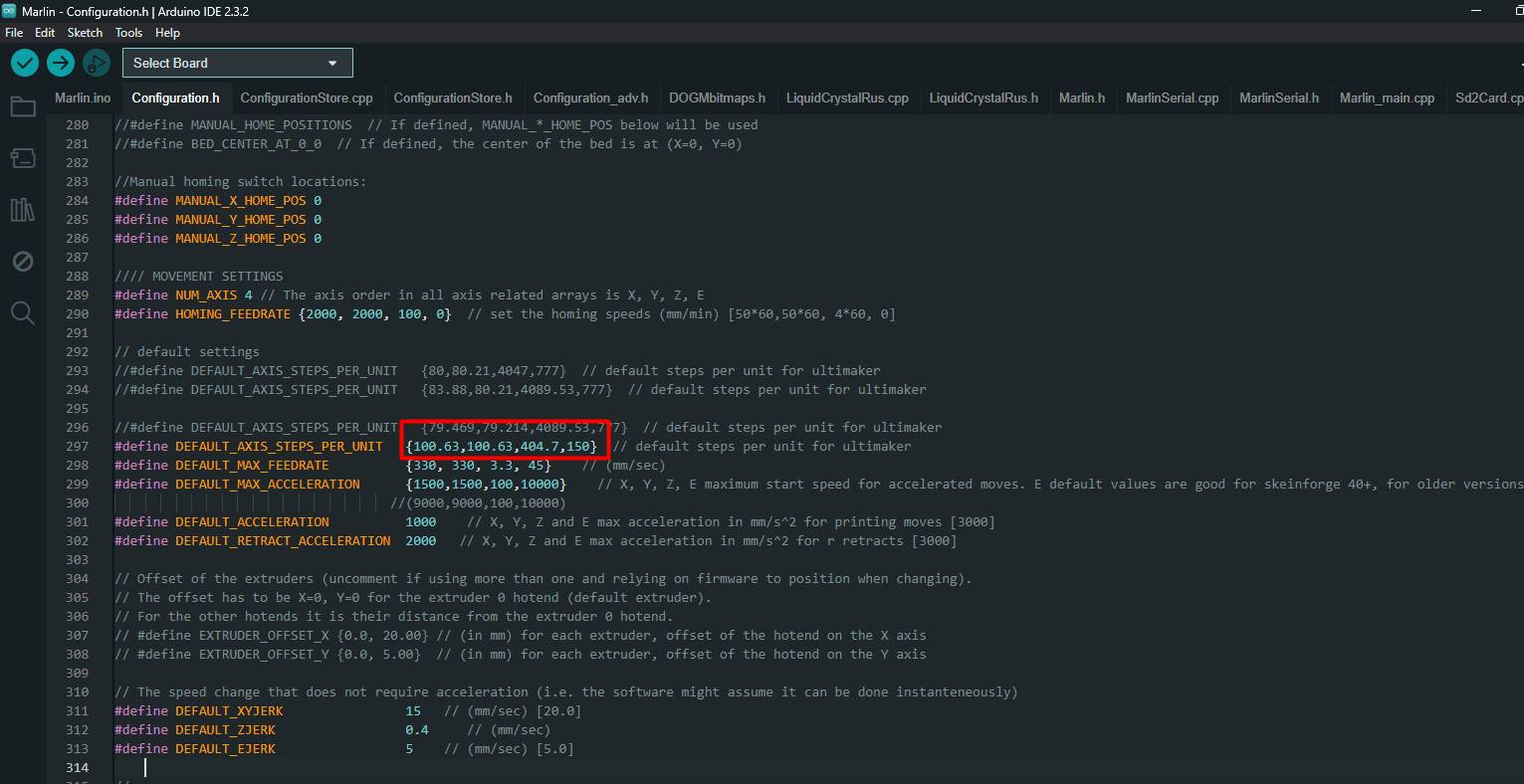
The line
#define DEFAULT_AXIS_STEPS_PER_UNIT {100.63,100.63,404.7,150}
sets the steps per unit for each of the 3D printer's axes. These values determine how many motor steps the motors must take to move a specific unit of measurement (usually millimeters). The list of values {100.63,100.63,404.7,150} refers to the X, Y, Z and E (extruder) axes, respectively.
• For the X axis, each millimeter of movement will require the motor to take 100.63 steps.
• For the Y axis, 100.63 steps per millimeter will also be needed.
• For the Z axis, 404.7 steps per millimeter will be needed.
• For the E axis (extruder), 150 steps per millimeter will be needed.
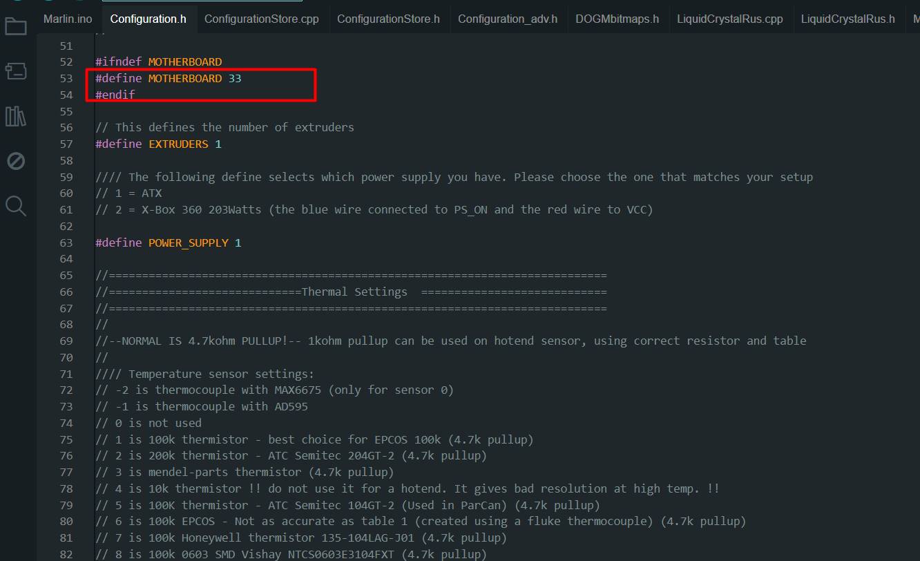 The
The
#define MOTHERBOARD 33
line specifies the type of motherboard you are using in your 3D printer. In this case, the value "33" corresponds to the code assigned to a specific motherboard.
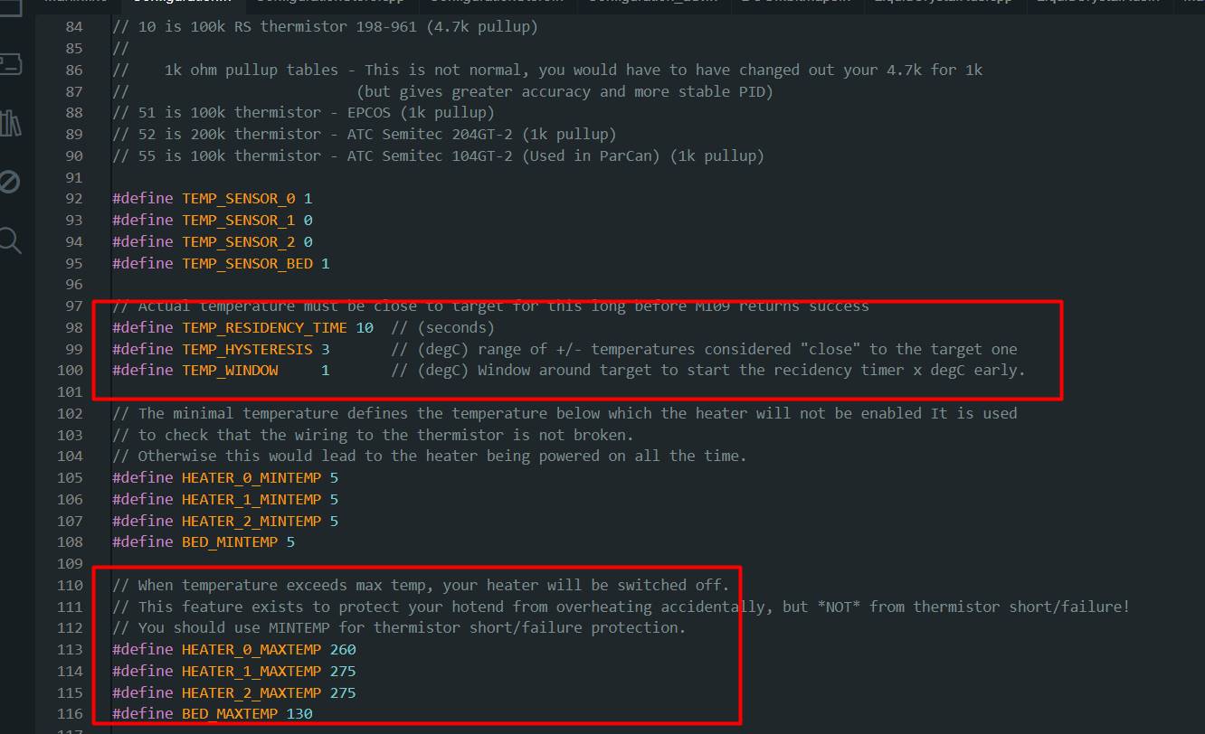
- HEATER_0_MAXTEMP: This parameter sets the maximum temperature allowed for the main hotend (extruder), which generally corresponds to the printer's primary extruder. In this case, it has been set to 260 degrees Celsius. If the hotend temperature exceeds this limit during printing, the heater will automatically turn off to prevent overheating.
- HEATER_1_MAXTEMP and HEATER_2_MAXTEMP: These parameters set the maximum temperature limits for the additional hotends, if the printer has more than one extruder. In this case, both have been set to 275 degrees Celsius.
- BED_MAXTEMP: This parameter sets the maximum temperature limit for the heated bed of the 3D printer. It has been set to 130 degrees Celsius. As with hotends, if the heated bed temperature exceeds this limit, the heater will automatically shut off to prevent overheating.
The program we use is called Marlin. It is an open source firmware designed primarily for 3D printers, but we realized that it could adapt perfectly to our food machine. With Marlin, we were able to precisely control every movement of our machine
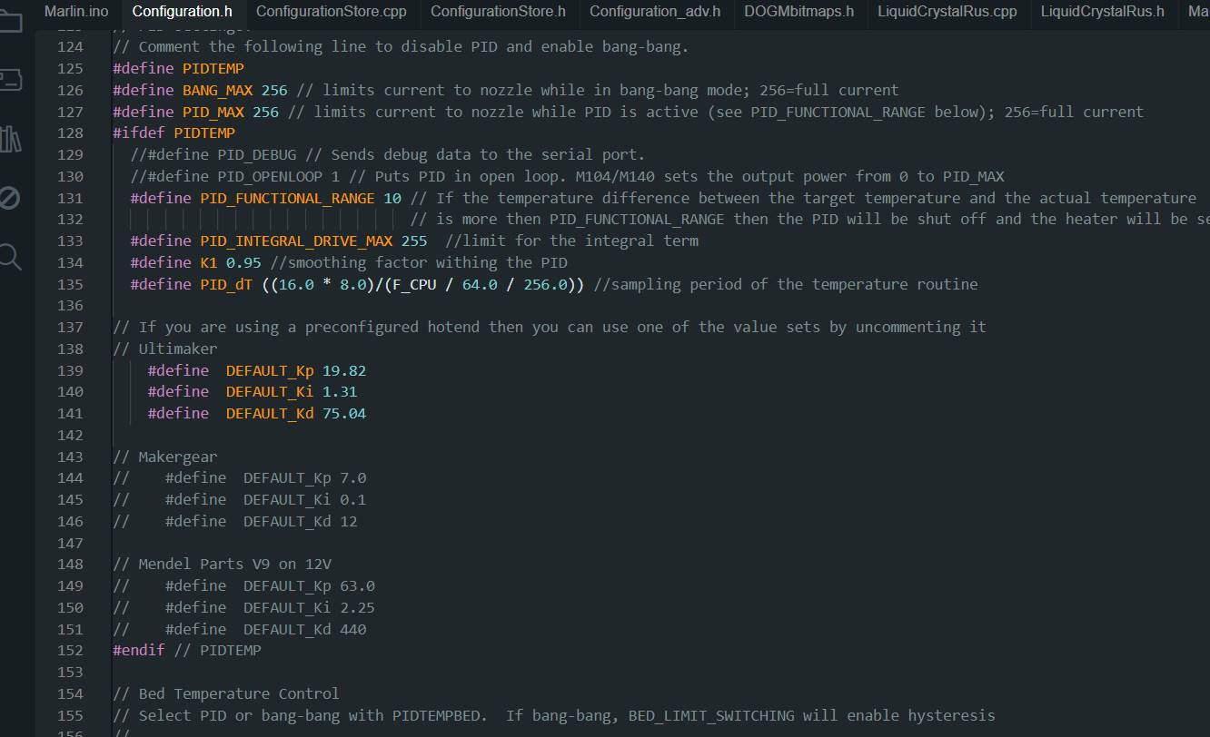
- PID_INTEGRAL_DRIVE_MAX: This parameter sets the maximum limit for the integral component of the PID control. The integral component is responsible for correcting the error accumulated over time. In this case, it has been set to 255, which is the maximum value for an unsigned byte.
- K1: This parameter is a smoothing factor used within PID control. Helps smooth out changes in controller output. In this case, it has been set to 0.95.
- PID_dT: This parameter specifies the sampling period of the PID control. It is the amount of time between each temperature reading used by the PID controller. In this case, it is calculated using the CPU frequency and other factors.
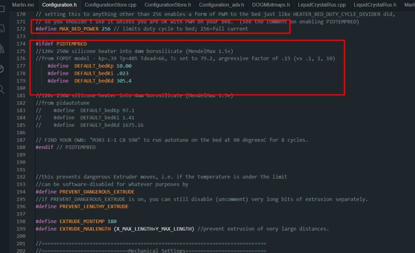
Although on this occasion we do not plan to use the heated bed in our machine, it is important to highlight its connection and presence.
The heated bed is not only essential for printing certain materials, but also plays a crucial role in the stability and accuracy of the overall print.
Maintaining the option to use the heated bed gives us flexibility and the ability to work with a wider variety of materials in the future. Additionally,
having the heated bed connected and ready for use prepares us for any future printing needs that may arise, thus ensuring that our machine is fully equipped and ready for any project we tackle.
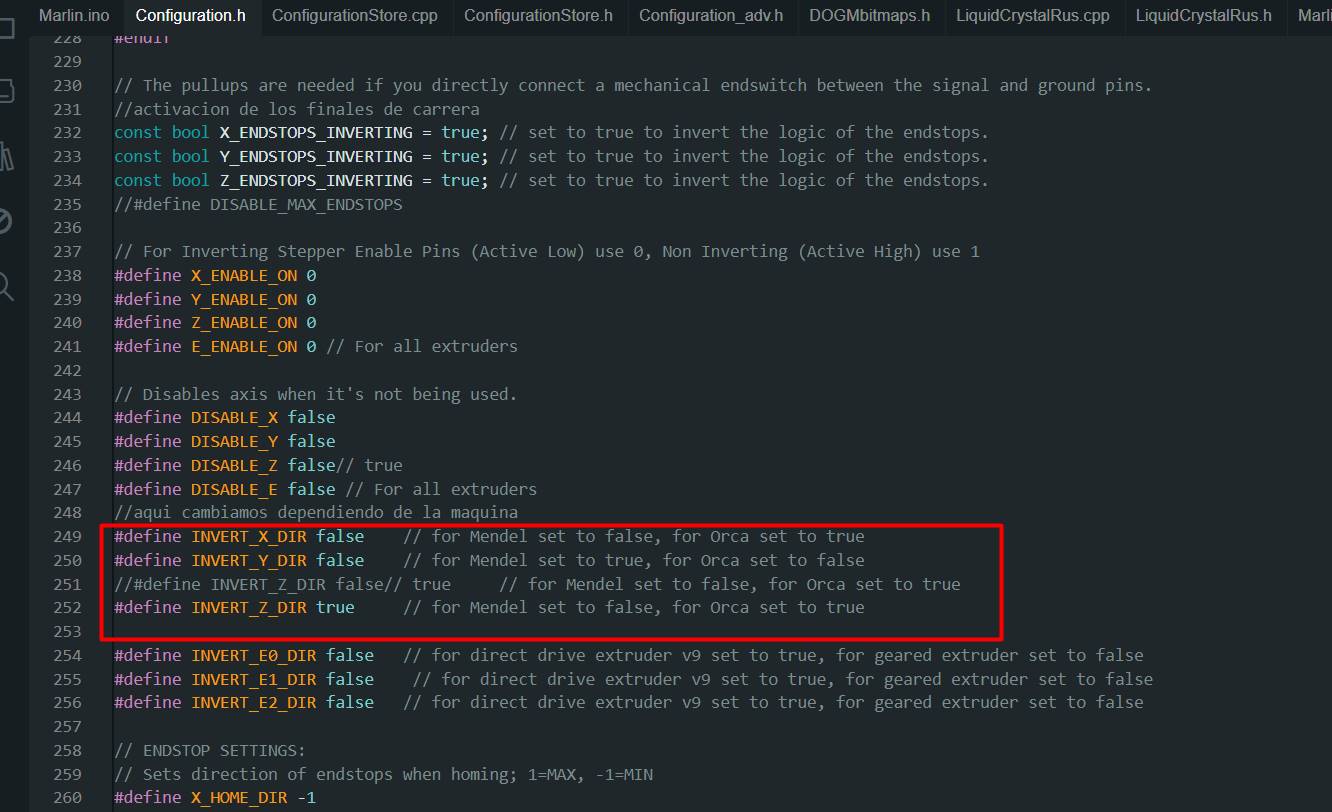
- INVERT_X_DIR: This parameter controls whether the motor direction for the X axis should be inverted or not. In this case, it has been set to false, which means that the motor direction for the X axis will not be reversed. For a Mendel type printer, this is usually correct.
- INVERT_Y_DIR: Similar to the previous one, this parameter controls the motor direction for the Y axis. Here it has also been set to false, which means that the motor direction for the Y axis will not be inverted. For a Mendel type printer, this is usually correct.
- INVERT_Z_DIR: This parameter controls the direction of the motor for the Z axis. It has been set to true, which means that the direction of the motor for the Z axis will be inverted. This is commonly necessary for an Orca type printer.
- INVERT_E0_DIR, INVERT_E1_DIR, INVERT_E2_DIR: These parameters control the motor direction for the extruders (E0, E1, E2 respectively). In this case, they have all been set to false, meaning that the motor direction for the extruders will not be reversed. This may vary depending on the type of extruder used in your printer (direct or geared).
Code
#ifndef CONFIGURATION_H
#define CONFIGURATION_H

// This configurtion file contains the basic settings.
// Advanced settings can be found in Configuration_adv.h
// BASIC SETTINGS: select your board type, temperature sensor type, axis scaling, and endstop configuration

//User specified version info of this build to display in [Pronterface, etc] terminal window during startup.
//Implementation of an idea by Prof Braino to inform user that any changes made
//to this build by the user have been successfully uploaded into firmware.
#define STRING_VERSION_CONFIG_H __DATE__ " " __TIME__ // build date and time
#define STRING_CONFIG_H_AUTHOR "Darth Raul" //Who made the changes.

// SERIAL_PORT selects which serial port should be used for communication with the host.
// This allows the connection of wireless adapters (for instance) to non-default port pins.
// Serial port 0 is still used by the Arduino bootloader regardless of this setting.
#define SERIAL_PORT 0

// This determines the communication speed of the printer
#define BAUDRATE 115200
//#define BAUDRATE 115200

//#define BTENABLED //Enable BT

//// The following define selects which electronics board you have. Please choose the one that matches your setup
// 10 = Gen7 custom (Alfons3 Version) "https://github.com/Alfons3/Generation_7_Electronics"
// 11 = Gen7 v1.1, v1.2 = 11
// 12 = Gen7 v1.3
// 13 = Gen7 v1.4
// 3  = MEGA/RAMPS up to 1.2 = 3
// 33 = RAMPS 1.3 / 1.4 (Power outputs: Extruder, Bed, Fan)
// 34 = RAMPS 1.3 / 1.4 (Power outputs: Extruder0, Extruder1, Bed)
// 4  = Duemilanove w/ ATMega328P pin assignment
// 5  = Gen6
// 51 = Gen6 deluxe
// 6  = Sanguinololu < 1.2
// 62 = Sanguinololu 1.2 and above
// 63 = Melzi
// 64 = STB V1.1
// 7  = Ultimaker
// 71 = Ultimaker (Older electronics. Pre 1.5.4. This is rare)
// 8  = Teensylu
// 80 = Rumba
// 81 = Printrboard (AT90USB1286)
// 82 = Brainwave (AT90USB646)
// 9  = Gen3+
// 70 = Megatronics
// 701= Megatronics v2.0
// 702= Minitronics v1.0
// 90 = Alpha OMCA board
// 91 = Final OMCA board
// 301 = Rambo

#ifndef MOTHERBOARD
#define MOTHERBOARD 33
#endif

// This defines the number of extruders
#define EXTRUDERS 1

//// The following define selects which power supply you have. Please choose the one that matches your setup
// 1 = ATX
// 2 = X-Box 360 203Watts (the blue wire connected to PS_ON and the red wire to VCC)

#define POWER_SUPPLY 1

//===========================================================================
//=============================Thermal Settings  ============================
//===========================================================================
//
//--NORMAL IS 4.7kohm PULLUP!-- 1kohm pullup can be used on hotend sensor, using correct resistor and table
//
//// Temperature sensor settings:
// -2 is thermocouple with MAX6675 (only for sensor 0)
// -1 is thermocouple with AD595
// 0 is not used
// 1 is 100k thermistor - best choice for EPCOS 100k (4.7k pullup)
// 2 is 200k thermistor - ATC Semitec 204GT-2 (4.7k pullup)
// 3 is mendel-parts thermistor (4.7k pullup)
// 4 is 10k thermistor !! do not use it for a hotend. It gives bad resolution at high temp. !!
// 5 is 100K thermistor - ATC Semitec 104GT-2 (Used in ParCan) (4.7k pullup)
// 6 is 100k EPCOS - Not as accurate as table 1 (created using a fluke thermocouple) (4.7k pullup)
// 7 is 100k Honeywell thermistor 135-104LAG-J01 (4.7k pullup)
// 8 is 100k 0603 SMD Vishay NTCS0603E3104FXT (4.7k pullup)
// 9 is 100k GE Sensing AL03006-58.2K-97-G1 (4.7k pullup)
// 10 is 100k RS thermistor 198-961 (4.7k pullup)
//
//    1k ohm pullup tables - This is not normal, you would have to have changed out your 4.7k for 1k
//                          (but gives greater accuracy and more stable PID)
// 51 is 100k thermistor - EPCOS (1k pullup)
// 52 is 200k thermistor - ATC Semitec 204GT-2 (1k pullup)
// 55 is 100k thermistor - ATC Semitec 104GT-2 (Used in ParCan) (1k pullup)

#define TEMP_SENSOR_0 1
//////////////////////////
#define TEMP_SENSOR_1 1
//#define TEMP_SENSOR_1 1
#define TEMP_SENSOR_2 0
#define TEMP_SENSOR_BED 1

// Actual temperature must be close to target for this long before M109 returns success
#define TEMP_RESIDENCY_TIME 10  // (seconds)
#define TEMP_HYSTERESIS 3       // (degC) range of +/- temperatures considered "close" to the target one
#define TEMP_WINDOW     1       // (degC) Window around target to start the recidency timer x degC early.

// The minimal temperature defines the temperature below which the heater will not be enabled It is used
// to check that the wiring to the thermistor is not broken.
// Otherwise this would lead to the heater being powered on all the time.
#define HEATER_0_MINTEMP 0
#define HEATER_1_MINTEMP 5
#define HEATER_2_MINTEMP 5
#define BED_MINTEMP 5

// When temperature exceeds max temp, your heater will be switched off.
// This feature exists to protect your hotend from overheating accidentally, but *NOT* from thermistor short/failure!
// You should use MINTEMP for thermistor short/failure protection.
#define HEATER_0_MAXTEMP 260
#define HEATER_1_MAXTEMP 275
#define HEATER_2_MAXTEMP 275
#define BED_MAXTEMP 130

// If your bed has low resistance e.g. .6 ohm and throws the fuse you can duty cycle it to reduce the
// average current. The value should be an integer and the heat bed will be turned on for 1 interval of
// HEATER_BED_DUTY_CYCLE_DIVIDER intervals.
//#define HEATER_BED_DUTY_CYCLE_DIVIDER 4

// PID settings:
// Comment the following line to disable PID and enable bang-bang.
#define PIDTEMP
#define BANG_MAX 256 // limits current to nozzle while in bang-bang mode; 256=full current
#define PID_MAX 256 // limits current to nozzle while PID is active (see PID_FUNCTIONAL_RANGE below); 256=full current
#ifdef PIDTEMP
  //#define PID_DEBUG // Sends debug data to the serial port.
  //#define PID_OPENLOOP 1 // Puts PID in open loop. M104/M140 sets the output power from 0 to PID_MAX
  #define PID_FUNCTIONAL_RANGE 10 // If the temperature difference between the target temperature and the actual temperature
                                  // is more then PID_FUNCTIONAL_RANGE then the PID will be shut off and the heater will be set to min/max. (10)
  #define PID_INTEGRAL_DRIVE_MAX 255  //limit for the integral term
  #define K1 0.95 //smoothing factor withing the PID
  #define PID_dT ((16.0 * 8.0)/(F_CPU / 64.0 / 256.0)) //sampling period of the temperature routine

// If you are using a preconfigured hotend then you can use one of the value sets by uncommenting it
// Ultimaker
    #define  DEFAULT_Kp 19.82
    #define  DEFAULT_Ki 1.31
    #define  DEFAULT_Kd 75.04

// Makergear
//    #define  DEFAULT_Kp 7.0
//    #define  DEFAULT_Ki 0.1
//    #define  DEFAULT_Kd 12

// Mendel Parts V9 on 12V
//    #define  DEFAULT_Kp 63.0
//    #define  DEFAULT_Ki 2.25
//    #define  DEFAULT_Kd 440
#endif // PIDTEMP

// Bed Temperature Control
// Select PID or bang-bang with PIDTEMPBED.  If bang-bang, BED_LIMIT_SWITCHING will enable hysteresis
//
// uncomment this to enable PID on the bed.   It uses the same frequency PWM as the extruder.
// If your PID_dT above is the default, and correct for your hardware/configuration, that means 7.689Hz,
// which is fine for driving a square wave into a resistive load and does not significantly impact you FET heating.
// This also works fine on a Fotek SSR-10DA Solid State Relay into a 250W heater.
// If your configuration is significantly different than this and you don't understand the issues involved, you proabaly
// shouldn't use bed PID until someone else verifies your hardware works.
// If this is enabled, find your own PID constants below.
//#define PIDTEMPBED
//
//#define BED_LIMIT_SWITCHING

// This sets the max power delived to the bed, and replaces the HEATER_BED_DUTY_CYCLE_DIVIDER option.
// all forms of bed control obey this (PID, bang-bang, bang-bang with hysteresis)
// setting this to anything other than 256 enables a form of PWM to the bed just like HEATER_BED_DUTY_CYCLE_DIVIDER did,
// so you shouldn't use it unless you are OK with PWM on your bed.  (see the comment on enabling PIDTEMPBED)
#define MAX_BED_POWER 256 // limits duty cycle to bed; 256=full current

#ifdef PIDTEMPBED
//120v 250W silicone heater into 4mm borosilicate (MendelMax 1.5+)
//from FOPDT model - kp=.39 Tp=405 Tdead=66, Tc set to 79.2, argressive factor of .15 (vs .1, 1, 10)
    #define  DEFAULT_bedKp 10.00
    #define  DEFAULT_bedKi .023
    #define  DEFAULT_bedKd 305.4

//120v 250W silicone heater into 4mm borosilicate (MendelMax 1.5+)
//from pidautotune
//    #define  DEFAULT_bedKp 97.1
//    #define  DEFAULT_bedKi 1.41
//    #define  DEFAULT_bedKd 1675.16

// FIND YOUR OWN: "M303 E-1 C8 S90" to run autotune on the bed at 90 degreesC for 8 cycles.
#endif // PIDTEMPBED


//this prevents dangerous Extruder moves, i.e. if the temperature is under the limit
//can be software-disabled for whatever purposes by
#define PREVENT_DANGEROUS_EXTRUDE
//if PREVENT_DANGEROUS_EXTRUDE is on, you can still disable (uncomment) very long bits of extrusion separately.
#define PREVENT_LENGTHY_EXTRUDE

#define EXTRUDE_MINTEMP 0
#define EXTRUDE_MAXLENGTH (X_MAX_LENGTH+Y_MAX_LENGTH) //prevent extrusion of very large distances.

//===========================================================================
//=============================Mechanical Settings===========================
//===========================================================================

// Uncomment the following line to enable CoreXY kinematics
// #define COREXY

// corse Endstop Settings
#define ENDSTOPPULLUPS // Comment this out (using // at the start of the line) to disable the endstop pullup resistors

#ifndef ENDSTOPPULLUPS
  // fine Enstop settings: Individual Pullups. will be ignord if ENDSTOPPULLUPS is defined
  #define ENDSTOPPULLUP_XMAX
  #define ENDSTOPPULLUP_YMAX
  #define ENDSTOPPULLUP_ZMAX
  #define ENDSTOPPULLUP_XMIN
  #define ENDSTOPPULLUP_YMIN
  //#define ENDSTOPPULLUP_ZMIN
#endif

#ifdef ENDSTOPPULLUPS
  #define ENDSTOPPULLUP_XMAX
  #define ENDSTOPPULLUP_YMAX
  #define ENDSTOPPULLUP_ZMAX
  #define ENDSTOPPULLUP_XMIN
  #define ENDSTOPPULLUP_YMIN
  #define ENDSTOPPULLUP_ZMIN
#endif

// The pullups are needed if you directly connect a mechanical endswitch between the signal and ground pins.
const bool X_ENDSTOPS_INVERTING = true; // set to true to invert the logic of the endstops.
const bool Y_ENDSTOPS_INVERTING = true; // set to true to invert the logic of the endstops.
const bool Z_ENDSTOPS_INVERTING = true; // set to true to invert the logic of the endstops.
//#define DISABLE_MAX_ENDSTOPS

// For Inverting Stepper Enable Pins (Active Low) use 0, Non Inverting (Active High) use 1
#define X_ENABLE_ON 0
#define Y_ENABLE_ON 0
#define Z_ENABLE_ON 0
#define E_ENABLE_ON 0 // For all extruders

// Disables axis when it's not being used.
#define DISABLE_X false
#define DISABLE_Y false
#define DISABLE_Z true
#define DISABLE_E false // For all extruders

#define INVERT_X_DIR false    // for Mendel set to false, for Orca set to true
#define INVERT_Y_DIR false    // for Mendel set to true, for Orca set to false
#define INVERT_Z_DIR true     // for Mendel set to false, for Orca set to true
#define INVERT_E0_DIR false   // for direct drive extruder v9 set to true, for geared extruder set to false
#define INVERT_E1_DIR false    // for direct drive extruder v9 set to true, for geared extruder set to false
#define INVERT_E2_DIR false   // for direct drive extruder v9 set to true, for geared extruder set to false

// ENDSTOP SETTINGS:
// Sets direction of endstops when homing; 1=MAX, -1=MIN
#define X_HOME_DIR -1
#define Y_HOME_DIR -1
#define Z_HOME_DIR -1

#define min_software_endstops true //If true, axis won't move to coordinates less than HOME_POS.
#define max_software_endstops true  //If true, axis won't move to coordinates greater than the defined lengths below.
// Travel limits after homing
#define X_MAX_POS 150
#define X_MIN_POS 0
#define Y_MAX_POS 150
#define Y_MIN_POS 0
#define Z_MAX_POS 150
#define Z_MIN_POS 0

#define X_MAX_LENGTH (X_MAX_POS - X_MIN_POS)
#define Y_MAX_LENGTH (Y_MAX_POS - Y_MIN_POS)
#define Z_MAX_LENGTH (Z_MAX_POS - Z_MIN_POS)

// The position of the homing switches
//#define MANUAL_HOME_POSITIONS  // If defined, MANUAL_*_HOME_POS below will be used
//#define BED_CENTER_AT_0_0  // If defined, the center of the bed is at (X=0, Y=0)

//Manual homing switch locations:
#define MANUAL_X_HOME_POS 0
#define MANUAL_Y_HOME_POS 0
#define MANUAL_Z_HOME_POS 0

//// MOVEMENT SETTINGS
#define NUM_AXIS 4 // The axis order in all axis related arrays is X, Y, Z, E
#define HOMING_FEEDRATE {2000, 2000, 100, 0}  // set the homing speeds (mm/min) [50*60,50*60, 4*60, 0]

// default settings
//#define DEFAULT_AXIS_STEPS_PER_UNIT   {80,80.21,4047,777}  // default steps per unit for ultimaker
//#define DEFAULT_AXIS_STEPS_PER_UNIT   {83.88,80.21,4089.53,777}  // default steps per unit for ultimaker

//#define DEFAULT_AXIS_STEPS_PER_UNIT   {79.469,79.214,4089.53,777}  // default steps per unit for ultimaker
#define DEFAULT_AXIS_STEPS_PER_UNIT   {100.63,100.63,404.7,150}  // default steps per unit for ultimaker
#define DEFAULT_MAX_FEEDRATE          {330, 330, 3.3, 45}    // (mm/sec)
#define DEFAULT_MAX_ACCELERATION      {1500,1500,100,10000}    // X, Y, Z, E maximum start speed for accelerated moves. E default values are good for skeinforge 40+, for older versions raise them a lot.
                                    //(9000,9000,100,10000)
#define DEFAULT_ACCELERATION          1000    // X, Y, Z and E max acceleration in mm/s^2 for printing moves [3000]
#define DEFAULT_RETRACT_ACCELERATION  2000   // X, Y, Z and E max acceleration in mm/s^2 for r retracts [3000]

// Offset of the extruders (uncomment if using more than one and relying on firmware to position when changing).
// The offset has to be X=0, Y=0 for the extruder 0 hotend (default extruder).
// For the other hotends it is their distance from the extruder 0 hotend.
// #define EXTRUDER_OFFSET_X {0.0, 20.00} // (in mm) for each extruder, offset of the hotend on the X axis
// #define EXTRUDER_OFFSET_Y {0.0, 5.00}  // (in mm) for each extruder, offset of the hotend on the Y axis

// The speed change that does not require acceleration (i.e. the software might assume it can be done instanteneously)
#define DEFAULT_XYJERK                15   // (mm/sec) [20.0]
#define DEFAULT_ZJERK                 0.4     // (mm/sec)
#define DEFAULT_EJERK                 5    // (mm/sec) [5.0]

//===========================================================================
//=============================Additional Features===========================
//===========================================================================

// EEPROM
// the microcontroller can store settings in the EEPROM, e.g. max velocity...
// M500 - stores paramters in EEPROM
// M501 - reads parameters from EEPROM (if you need reset them after you changed them temporarily).
// M502 - reverts to the default "factory settings".  You still need to store them in EEPROM afterwards if you want to.
//define this to enable eeprom support
//#define EEPROM_SETTINGS
//to disable EEPROM Serial responses and decrease program space by ~1700 byte: comment this out:
// please keep turned on if you can.
//#define EEPROM_CHITCHAT

// Preheat Constants
#define PLA_PREHEAT_HOTEND_TEMP 210
#define PLA_PREHEAT_HPB_TEMP 50
#define PLA_PREHEAT_FAN_SPEED 255   // Insert Value between 0 and 255

#define ABS_PREHEAT_HOTEND_TEMP 230
#define ABS_PREHEAT_HPB_TEMP 100
#define ABS_PREHEAT_FAN_SPEED 130   // Insert Value between 0 and 255 (tenia 255)

//LCD and SD support
//#define ULTRA_LCD  //general lcd support, also 16x2
//#define DOGLCD  // Support for SPI LCD 128x64 (Controller ST7565R graphic Display Family)
//#define SDSUPPORT // Enable SD Card Support in Hardware Console
//#define SDSLOW // Use slower SD transfer mode (not normally needed - uncomment if you're getting volume init error)

//#define ULTIMAKERCONTROLLER //as available from the ultimaker online store.
//#define ULTIPANEL  //the ultipanel as on thingiverse

// The RepRapDiscount Smart Controller (white PCB)
// http://reprap.org/wiki/RepRapDiscount_Smart_Controller
//#define REPRAP_DISCOUNT_SMART_CONTROLLER

// The GADGETS3D G3D LCD/SD Controller (blue PCB)
// http://reprap.org/wiki/RAMPS_1.3/1.4_GADGETS3D_Shield_with_Panel
//#define G3D_PANEL //(cambiado, le he quitado las // del principio)

//The RepRapDiscount FULL GRAPHIC Smart Controller (quadratic white PCB)
// http://reprap.org/wiki/RepRapDiscount_Full_Graphic_Smart_Controller
//
// ==> REMEMBER TO INSTALL U8glib to your ARDUINO library folder: http://code.google.com/p/u8glib/wiki/u8glib
#define REPRAP_DISCOUNT_FULL_GRAPHIC_SMART_CONTROLLER

// The RepRapWorld REPRAPWORLD_KEYPAD v1.1
// http://reprapworld.com/?products_details&products_id=202&cPath=1591_1626
//#define REPRAPWORLD_KEYPAD
//#define REPRAPWORLD_KEYPAD_MOVE_STEP 10.0 // how much should be moved when a key is pressed, eg 10.0 means 10mm per click

//automatic expansion
#if defined (REPRAP_DISCOUNT_FULL_GRAPHIC_SMART_CONTROLLER)
 #define DOGLCD
 #define U8GLIB_ST7920
 #define REPRAP_DISCOUNT_SMART_CONTROLLER
#endif

#if defined(ULTIMAKERCONTROLLER) || defined(REPRAP_DISCOUNT_SMART_CONTROLLER) || defined(G3D_PANEL)
 #define ULTIPANEL
 #define NEWPANEL
#endif

#if defined(REPRAPWORLD_KEYPAD)
  #define NEWPANEL
  #define ULTIPANEL
#endif

//I2C PANELS

//#define LCD_I2C_SAINSMART_YWROBOT
#ifdef LCD_I2C_SAINSMART_YWROBOT
  // This uses the LiquidCrystal_I2C library ( https://bitbucket.org/fmalpartida/new-liquidcrystal/wiki/Home )
  // Make sure it is placed in the Arduino libraries directory.
  #define LCD_I2C_TYPE_PCF8575
  #define LCD_I2C_ADDRESS 0x27   // I2C Address of the port expander
  #define NEWPANEL
  #define ULTIPANEL
#endif

// PANELOLU2 LCD with status LEDs, separate encoder and click inputs
//#define LCD_I2C_PANELOLU2
#ifdef LCD_I2C_PANELOLU2
  // This uses the LiquidTWI2 library v1.2.3 or later ( https://github.com/lincomatic/LiquidTWI2 )
  // Make sure the LiquidTWI2 directory is placed in the Arduino or Sketchbook libraries subdirectory.
  // (v1.2.3 no longer requires you to define PANELOLU in the LiquidTWI2.h library header file)
  // Note: The PANELOLU2 encoder click input can either be directly connected to a pin
  //       (if BTN_ENC defined to != -1) or read through I2C (when BTN_ENC == -1).
  #define LCD_I2C_TYPE_MCP23017
  #define LCD_I2C_ADDRESS 0x20 // I2C Address of the port expander
  #define LCD_USE_I2C_BUZZER //comment out to disable buzzer on LCD
  #define NEWPANEL
  #define ULTIPANEL
#endif

// Panucatt VIKI LCD with status LEDs, integrated click & L/R/U/P buttons, separate encoder inputs
//#define LCD_I2C_VIKI
#ifdef LCD_I2C_VIKI
  // This uses the LiquidTWI2 library v1.2.3 or later ( https://github.com/lincomatic/LiquidTWI2 )
  // Make sure the LiquidTWI2 directory is placed in the Arduino or Sketchbook libraries subdirectory.
  // Note: The pause/stop/resume LCD button pin should be connected to the Arduino
  //       BTN_ENC pin (or set BTN_ENC to -1 if not used)
  #define LCD_I2C_TYPE_MCP23017
  #define LCD_I2C_ADDRESS 0x20 // I2C Address of the port expander
  #define LCD_USE_I2C_BUZZER //comment out to disable buzzer on LCD (requires LiquidTWI2 v1.2.3 or later)
  #define NEWPANEL
  #define ULTIPANEL
#endif

#ifdef ULTIPANEL
//  #define NEWPANEL  //enable this if you have a click-encoder panel
  #define SDSUPPORT
  #define ULTRA_LCD
  #ifdef DOGLCD // Change number of lines to match the DOG graphic display
    #define LCD_WIDTH 20
    #define LCD_HEIGHT 5
  #else
    #define LCD_WIDTH 20
    #define LCD_HEIGHT 4
  #endif
#else //no panel but just lcd
  #ifdef ULTRA_LCD
  #ifdef DOGLCD // Change number of lines to match the 128x64 graphics display
    #define LCD_WIDTH 20
    #define LCD_HEIGHT 5
  #else
    #define LCD_WIDTH 16
    #define LCD_HEIGHT 2
  #endif
  #endif
#endif

// Increase the FAN pwm frequency. Removes the PWM noise but increases heating in the FET/Arduino
//#define FAST_PWM_FAN

// M240  Triggers a camera by emulating a Canon RC-1 Remote
// Data from: http://www.doc-diy.net/photo/rc-1_hacked/
// #define PHOTOGRAPH_PIN     23

// SF send wrong arc g-codes when using Arc Point as fillet procedure
//#define SF_ARC_FIX

// Support for the BariCUDA Paste Extruder.
//#define BARICUDA

/*********************************************************************\
*
* R/C SERVO support
*
* Sponsored by TrinityLabs, Reworked by codexmas
*
**********************************************************************/

// Number of servos
//
// If you select a configuration below, this will receive a default value and does not need to be set manually
// set it manually if you have more servos than extruders and wish to manually control some
// leaving it undefined or defining as 0 will disable the servo subsystem
// If unsure, leave commented / disabled
//
// #define NUM_SERVOS 3

#include "Configuration_adv.h"
#include "thermistortables.h"

#endif //__CONFIGURATION_H
Final result
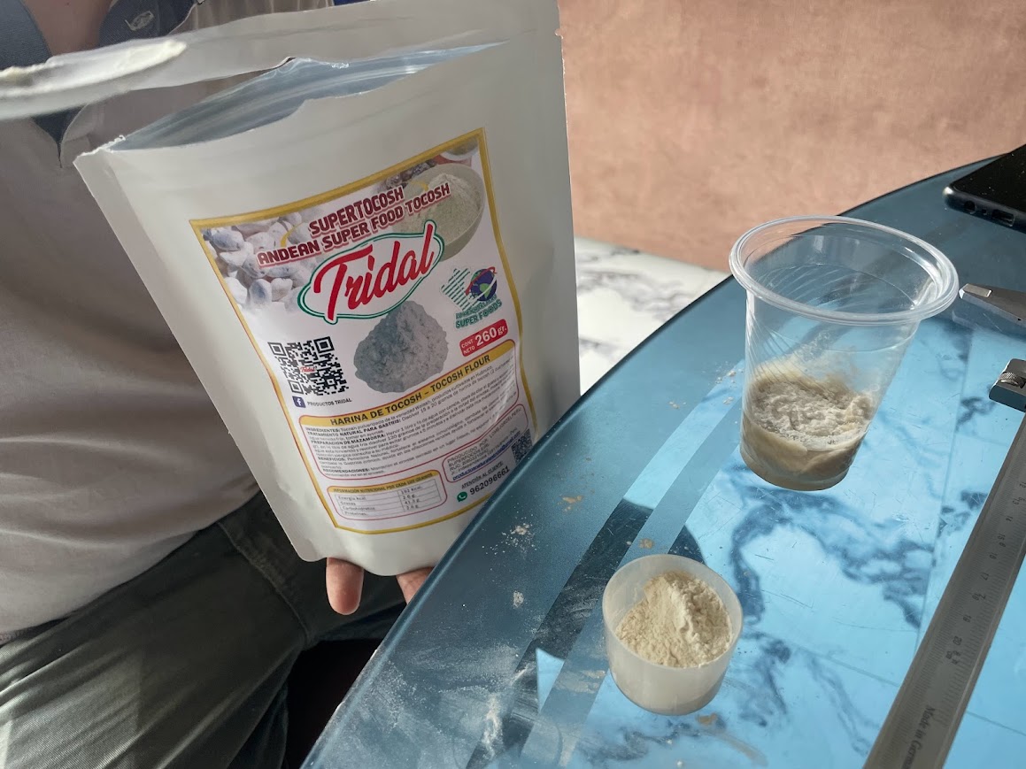
After experimenting with different ratios, grinding methods, and considering the moisture of the ingredients, we concluded that creating a layered superfood blend combining maca, banana flour, presents particular challenges in terms of consistency.
Clearly, finding the right balance between these ingredients requires a careful approach and perhaps the incorporation of natural binding agents. Although the initial results were not as expected, I am committed to continuing to explore new formulas and processing techniques to achieve a blend that takes full advantage of the nutritional benefits of these superfoods without compromising their consistency.
With patience and perseverance, I am confident that we will eventually find the perfect combination to create a final product that satisfies both in terms of health and quality.
Analyzing the flavor with my team For a possible improvement in this project we could add a little honey to the maca consumable to make it sweeter, since maca can be a little sour.
In our version number 1 the board we are using is an arduino mega with a 3D Printer Controller Board RAMPS 1.4 Arduino Mega Shield
Calibration is important for the machine, so in programming the Marlin with Arduino, adjustments were made to control the extruder motor and thus output the appropriate amount of material.
Marlin
Link