Input devices
In my week 8 you can see the process of making my own board

WEEK GROUP
Design Board Gyroscope Sensor Sound sensor Sensor de audio Group assignment
Conclusions
- Have you answered these questions?
- Linked to the group assignment page.
- Documented what you learned from interfacing an input device(s) to your microcontroller and optionally, how the physical property relates to the measured results.
- Documented your design and fabrication process or linked to the board you made in a previous assignment.
- Explained the programming process(es) you used.
- Explained any problems you encountered and how you fixed them.
- Included original design files and source code.
- Included a ‘hero shot’ of your board.
Assignments
-
Individual assignment:
- Measure something: add a sensor to a microcontroller board that you have designed and read it Group assignment:
- Probe an input device's analog levels and digital signals
- Document your work on the group work page and reflect on your individual page what you learned
Planning

I was planning the sensors I had to see which one I could use, I found in the laboratory the temperature sensor, gyroscope sensor, body temperature sensor, rain sensor, motion sensor, sound sensor, all of these are outputs, I have some that are for fabric. I will be choosing three to try.
Why would I use some sensors?
- Body temperature sensor: You could use this sensor to monitor a person's body temperature. It would be useful in health or wellness applications. For example, you could design a wearable device that alerts the user if their body temperature exceeds a certain threshold, which could indicate a fever or other health problems.
- Motion Sensor: This sensor is useful for detecting movement in your environment. You could use it in security applications, such as an alarm system that activates when someone moves near an unauthorized entrance. It could also be useful in home automation projects, such as turning on lights when someone enters a room.
- Rain sensor: With this sensor, you can detect if it is raining. It would be useful in projects related to climate monitoring or automating garden irrigation. For example, you could design a system that automatically closes the windows when it starts to rain to prevent water from entering the interior.
Gyroscope Sensor
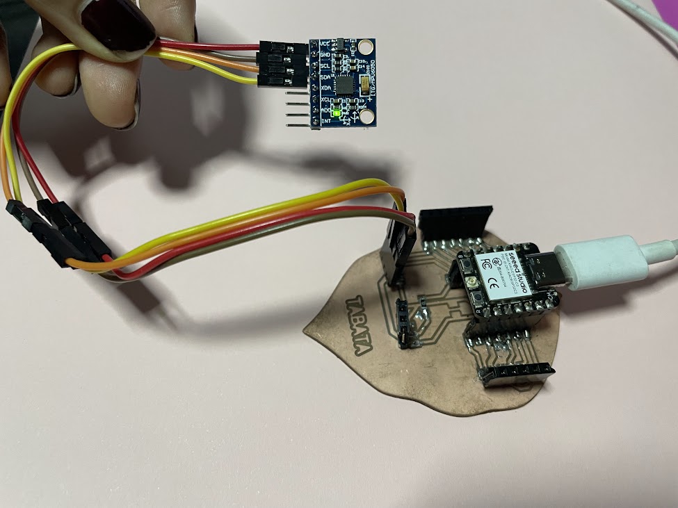
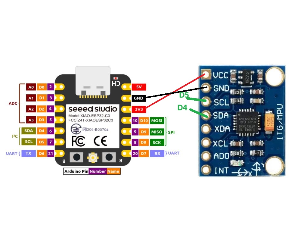
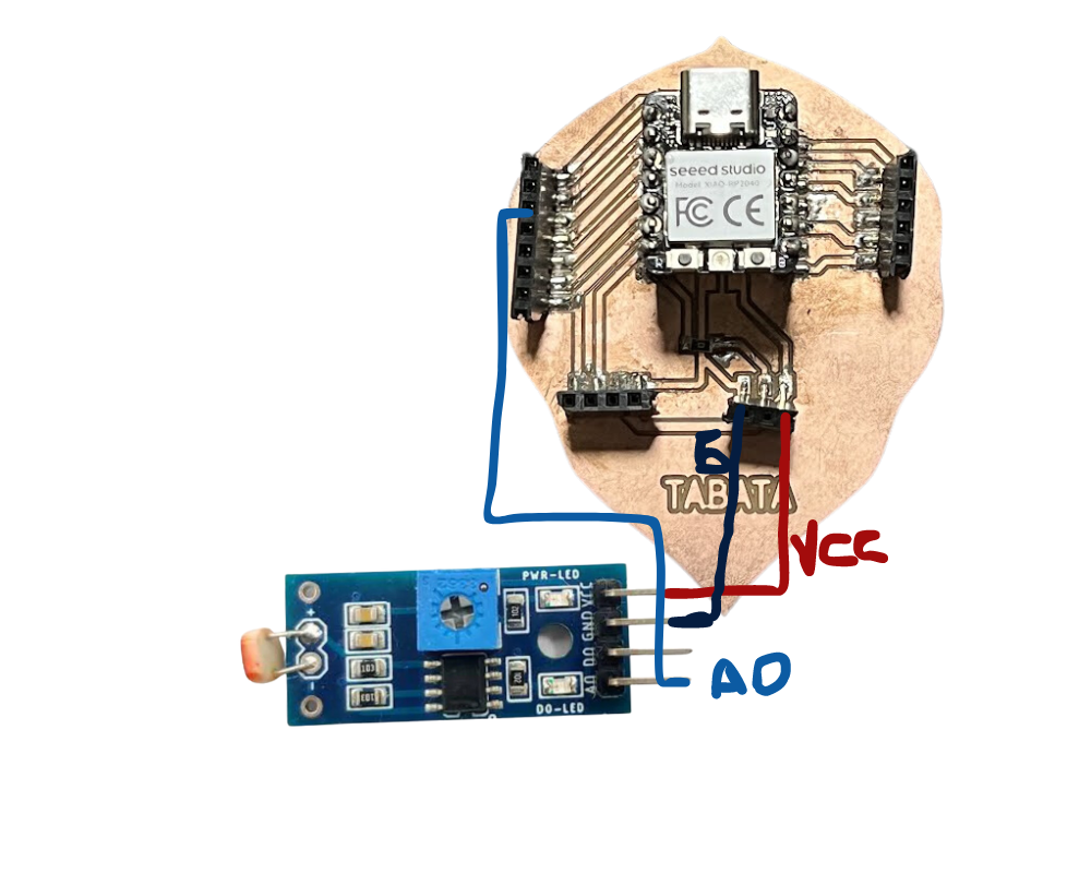
Connect the MPU6050 module to the Xiao. The MPU6050 communicates via the I2C protocol, so you only need to connect the SDA and SCL pins of the MPU6050 to the SDA pin (A4) and SCL (A5) of the xiao, respectively. Also, make sure to connect the VCC pin of the MPU6050 to the 5V pin of the xiao and the GND pin of the MPU6050 to the GND pin of the xiao.
SPECIFICATIONS
- Communication: Uses the I2C (Inter-Integrated Circuit) communication protocol for communication with other devices, such as an Arduino board.
- Accelerometer Measurement Range: The MPU6050 can measure acceleration in all three axes with a selectable range of ±2g, ±4g, ±8g or ±16g, where "g" represents Earth's gravity (approximately 9.8 m/s²).
- Gyroscope measurement range: It can measure rotation speed in all three axes with a selectable range of ±250, ±500, ±1000, or ±2000 degrees per second (dps).
- Humidity measurement resolution: 1% RH
- Both the accelerometer and gyroscope have 16-bit resolution, meaning they can represent values of up to 65536 different units on each axis.
- The MPU6050 can sample data at a programmable rate, with a maximum sampling rate of up to 8 kHz.
- Operates with a typical supply voltage of 3.3V, although it can also be powered with 5V.
- It has relatively low power consumption, making it suitable for battery-powered applications.
- It can operate in a temperature range of -40°C to +85°C, making it suitable for a variety of environments./li>
I tell you that here we connected the gyroscope module at 5V and it was working correctly, until it stopped working after a while, we knew that it could total an input voltage of 3 to 5V but it burned out because the appropriate thing would be to place it at 3.3V

Here I got a new one, we all learned the lesson and we know that the MPU6050 works with 3.3 V.

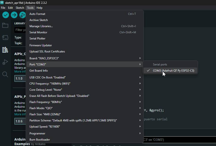
Remember that you must connect the board you are using to the ARduinoIDE so that you do not have problems when uploading it, also see which COM port it is connected to, with all this we can start
Serial Communication
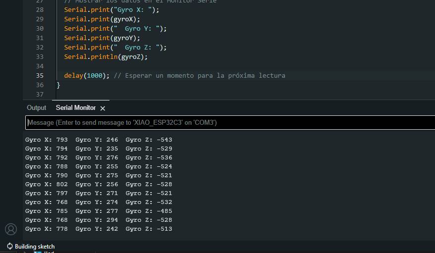
Tests Gyroscope with XIAO ESP32 C3
Gyroscope calibration is an important step in obtaining accurate and reliable measurements. Here I show you how you could calibrate the MPU6050 gyroscope on the Arduino before you start reading the gyro data:
This code first performs a gyro calibration in the calibrateGyro() function. During calibration, it takes multiple samples of gyroscope readings and calculates the average of these samples. Then, apply this average as an offset to the gyro using the setXGyroOffset(), setYGyroOffset(), and setZGyroOffset() functions. Once the calibration has been performed in the setup() function, the code enters the main loop in loop(), where it continuously reads the data from the gyroscope and displays it on the serial port. This is just a basic example, but you can expand it according to your needs, such as adding calibration output conditions or adjusting the calibration duration and frequency as needed.
LDR sensor
Board
NeoPixels
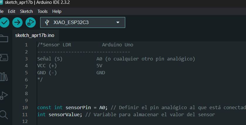
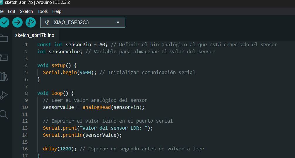
Sensor LDR
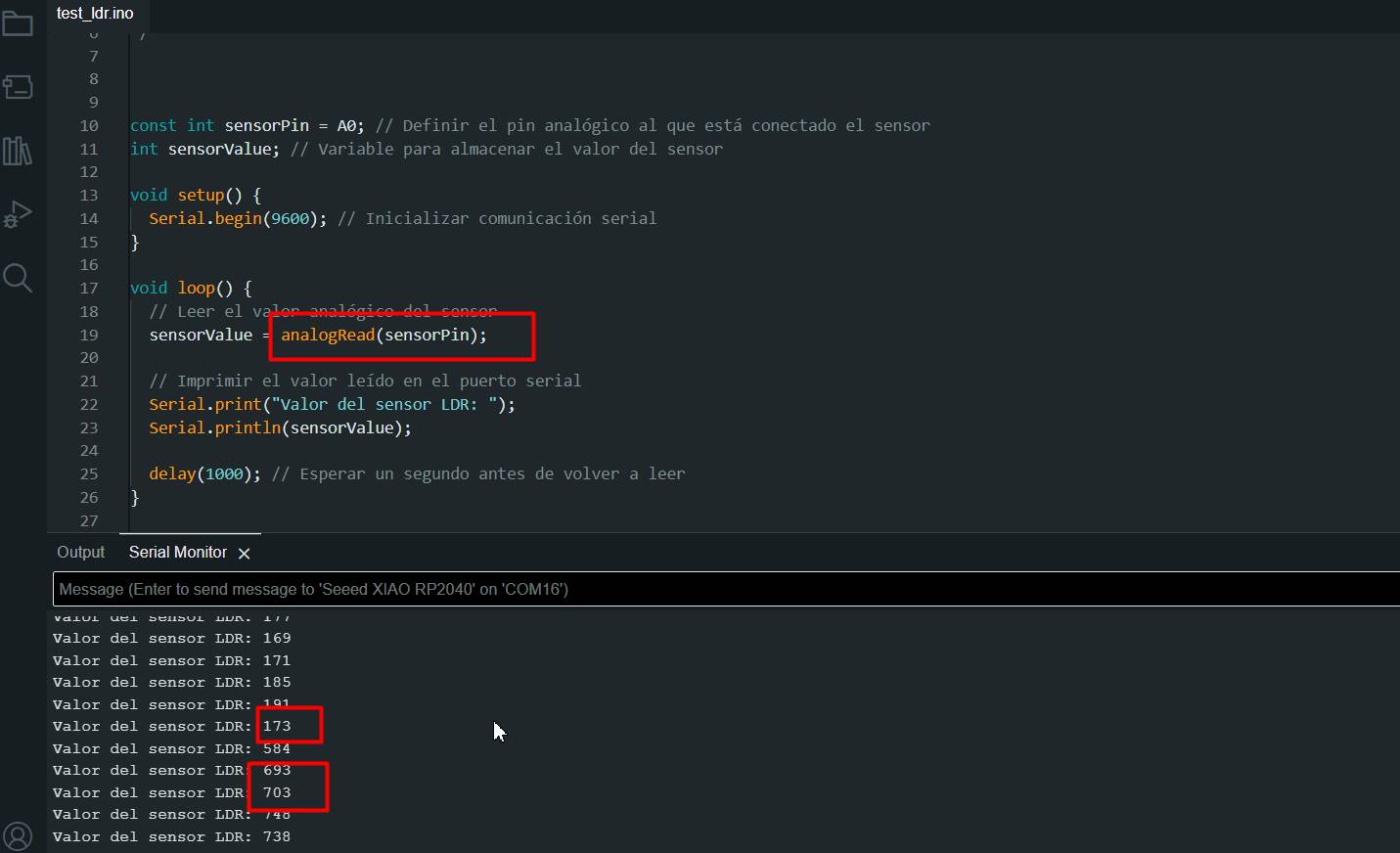
analogRead
Used to read analog sensor values.Returns a value between 0 and 1023 on most microcontrollers representing the voltage measured at the input pin.
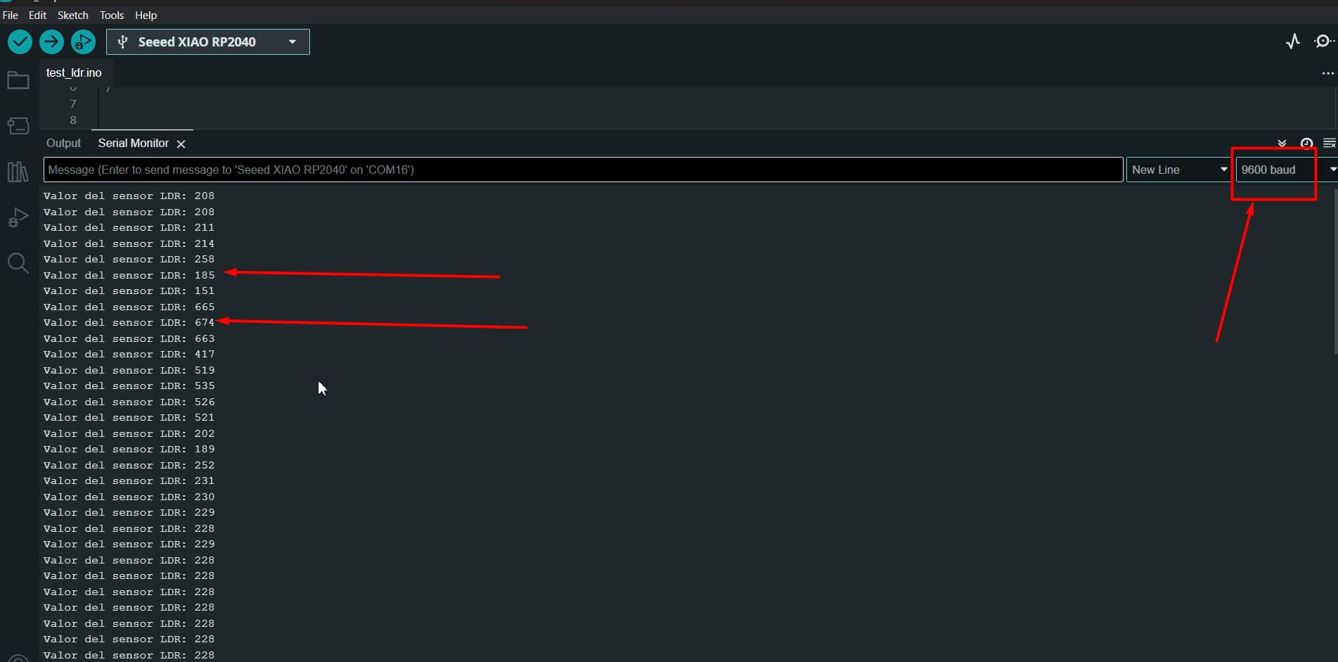
First I did the sensor test to check that everything was working correctly.
I started analyzing the program a little more to understand how the sensor works and look for information.
NEOPIXEL WITH LDR
DigitalRead
Used to read digital pin states. It returns HIGH or LOW (1 or 0), indicating whether the input pin is in a high or low voltage state.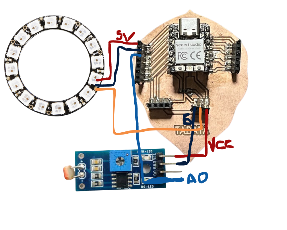
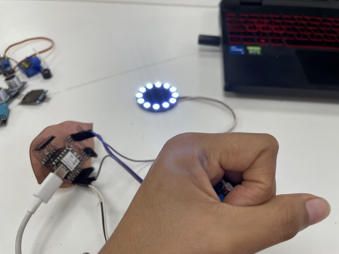
Here I cover the sensor with my hand and the neopixel caught fire.
#include

#define PIN_LED    6 // Pin al que está conectado el anillo de NeoPixel
#define NUM_LEDS   12 // Número de LEDs en el anillo

Adafruit_NeoPixel pixels = Adafruit_NeoPixel(NUM_LEDS, PIN_LED, NEO_GRB + NEO_KHZ800);

void setup() {
  pixels.begin();
  pixels.show(); // Initialize all pixels to 'off'
}

void loop() {
  encenderLuces(); // Enciende las luces NeoPixel
}

// Función para encender las luces NeoPixel
void encenderLuces() {
  for (int i = 0; i < NUM_LEDS; i++) {
    pixels.setPixelColor(i, pixels.Color(255, 255, 255)); // Color blanco
  }
  pixels.show(); // Muestra los cambios en los LEDs
}
Now I leave it in natural light and it turns off.
Sound sensor with LED
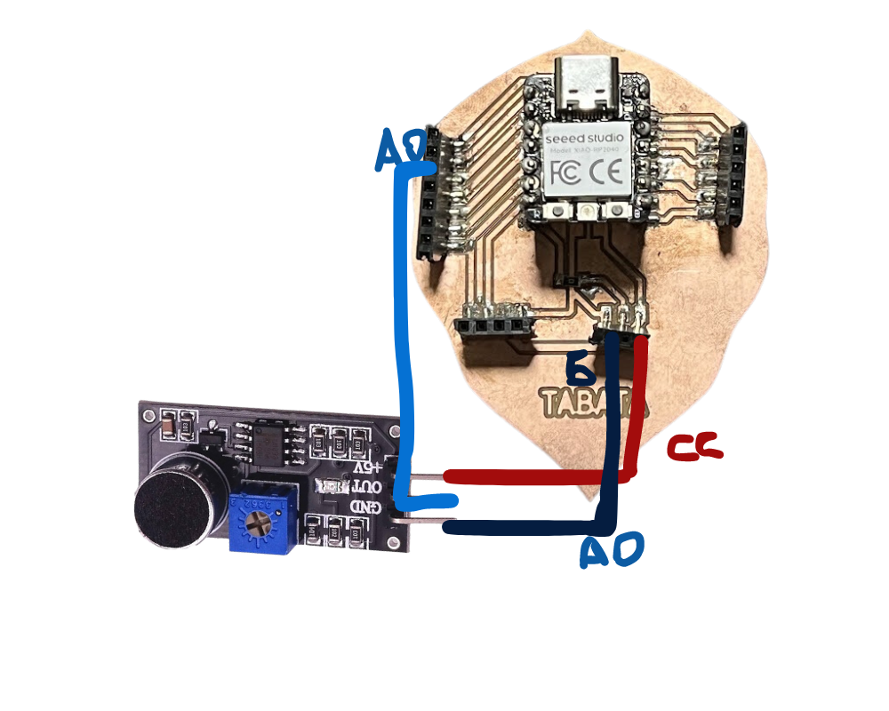
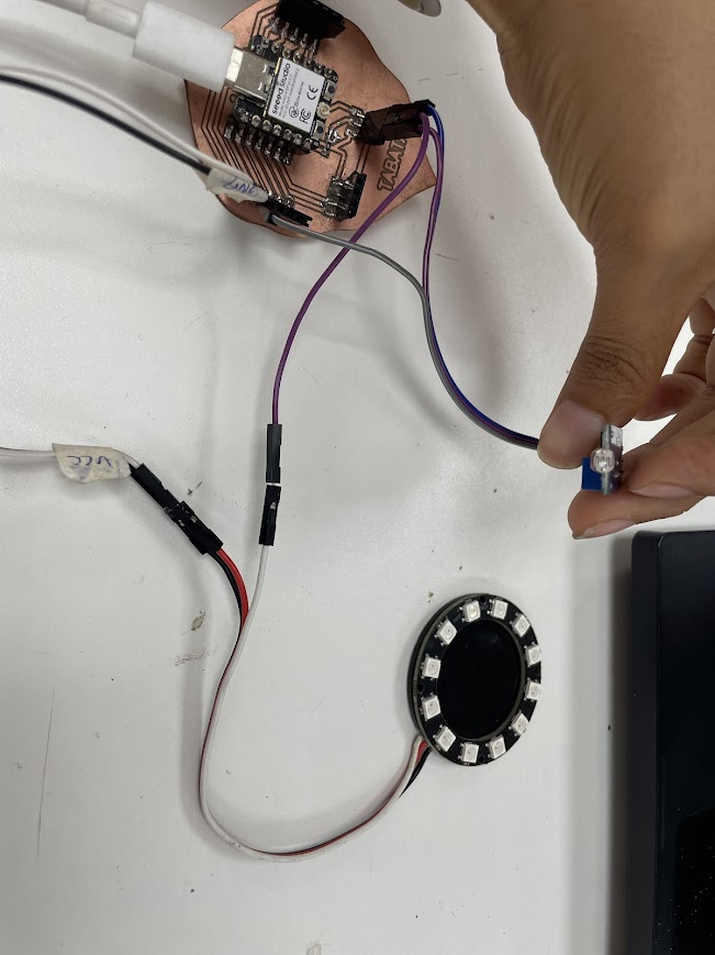
The test with the sound sensor was to turn on an LED with noise generated by a hiss.
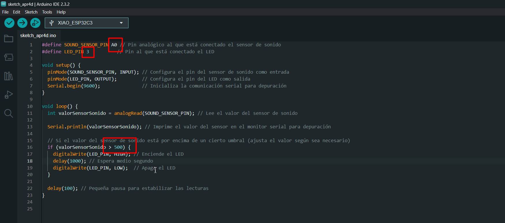
I made the respective connections with the xiao for correct operation
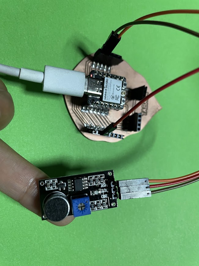
We can see how the connection was
Final
Final Project Test
Digital sensors with DTH11
Program
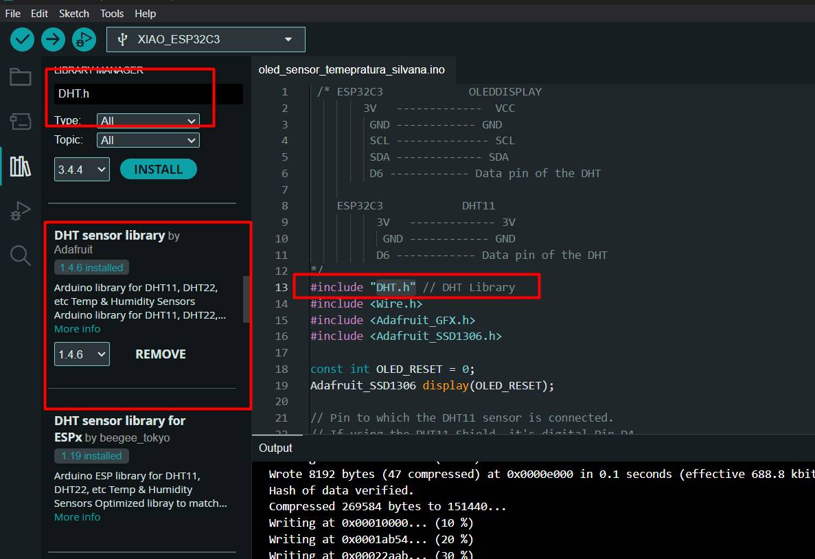
To make sure I got accurate readings from my DHT sensor on the Arduino, I installed the DHT.h library carefully and correctly. First, I opened the Arduino IDE and navigated to the "Sketch" menu, then "Include Library" and finally "Manage Libraries". In the search box, I entered "DHT" and found Adafruit's DHT Sensor Library. After selecting it, I clicked "Install" and waited for the process to complete.
Code
 /* ESP32C3             OLEDDISPLAY
        3V   -------------  VCC
         GND ------------ GND
         SCL -------------- SCL
         SDA ------------- SDA
         D6 ------------ Data pin of the DHT

    ESP32C3            DHT11
          3V   ------------- 3V
           GND ------------ GND
          D6 ------------ Data pin of the DHT
*/
#include "DHT.h" // DHT Library
#include < Wire.h >
#include < Adafruit_GFX.h>
#include < Adafruit_SSD1306.h>

const int OLED_RESET = 0;
Adafruit_SSD1306 display(OLED_RESET);

// Pin to which the DHT11 sensor is connected.
// If using the DHT11 Shield, it's digital Pin D4.
const int DHTPIN = D6;

// Specify the type of DHT sensor being used.
#define DHTTYPE DHT11

// Initialize the sensor with the pin and type.
DHT dht(DHTPIN, DHTTYPE);

void setup() {
  Serial.begin(115200); // Begin serial communication at 9600 Baud.
  Wire.begin();

  display.begin(SSD1306_SWITCHCAPVCC, 0x3C);
  display.display();
  delay(2000);
  display.clearDisplay();
  dht.begin(); // Start DHT communication.
}

void loop() {
  // The DHT11 sensor provides a new reading every 2 seconds,
  // so there's no need to constantly loop in the program.
  delay(2000);

  // Read humidity value.
  double humidity = dht.readHumidity();
  // Read temperature in Celsius.
  double temperatureC = dht.readTemperature();
  // Read temperature in Fahrenheit.
  // The boolean parameter controls whether
  // the temperature is displayed in Fahrenheit or Celsius.
  double temperatureF = dht.readTemperature(true);

  // Check if the values were read successfully.
  if (isnan(humidity) || isnan(temperatureC) || isnan(temperatureF)) {
    Serial.println("Error reading data.");
    return;
  }

  display.clearDisplay();
  display.setTextSize(1);
  display.setTextColor(WHITE);

  display.setCursor(5, 0);
  display.println("Fab Academy");

  display.setCursor(5, 15);
  String tempValue = String(temperatureC);
  display.println("Temp: " + tempValue + "C");

  display.setCursor(5, 23);
  String humValue = String(humidity);
  display.println("Humidity: " + humValue + "%");

  display.display();
  delay(500);
}
March 23
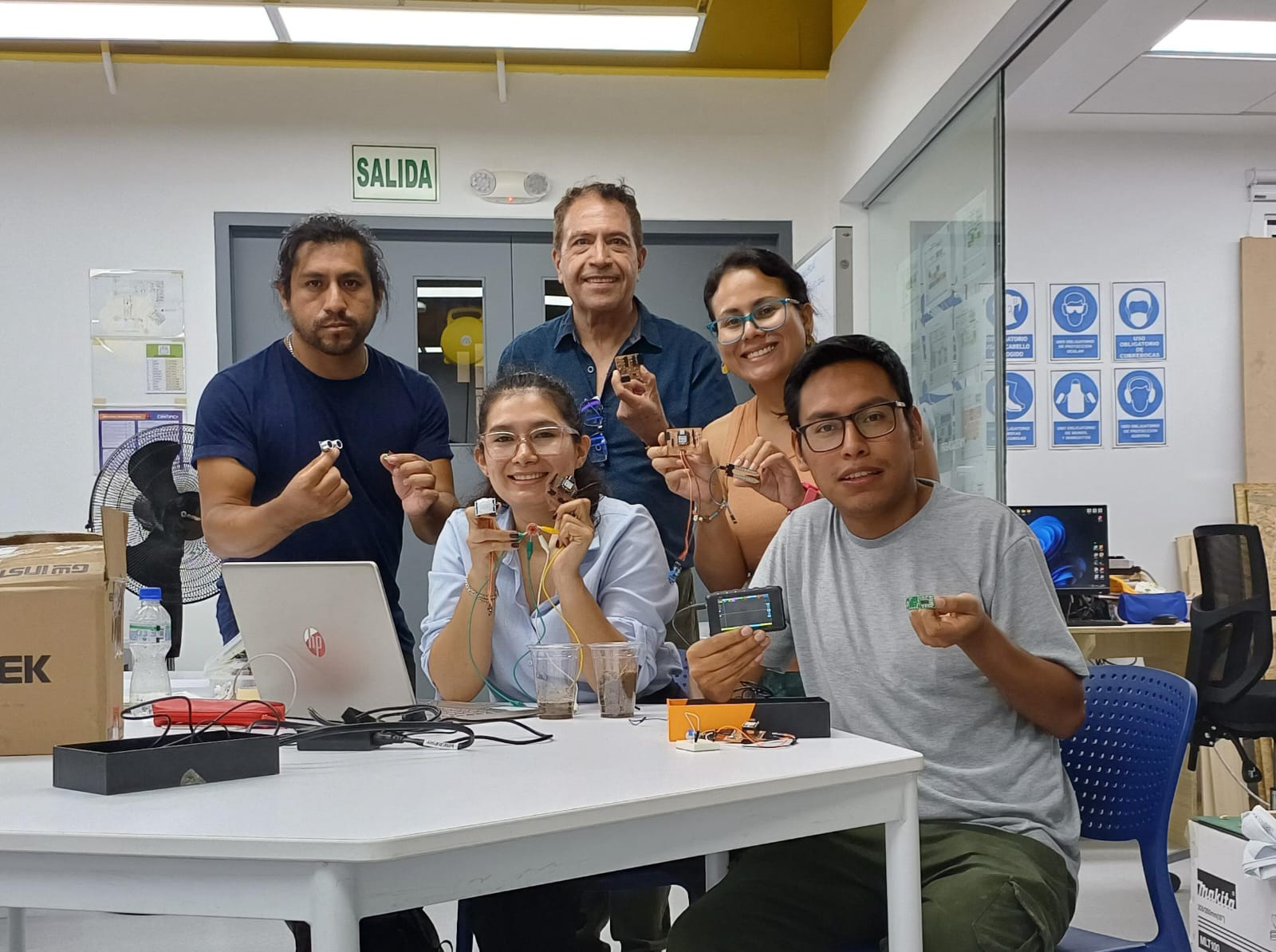
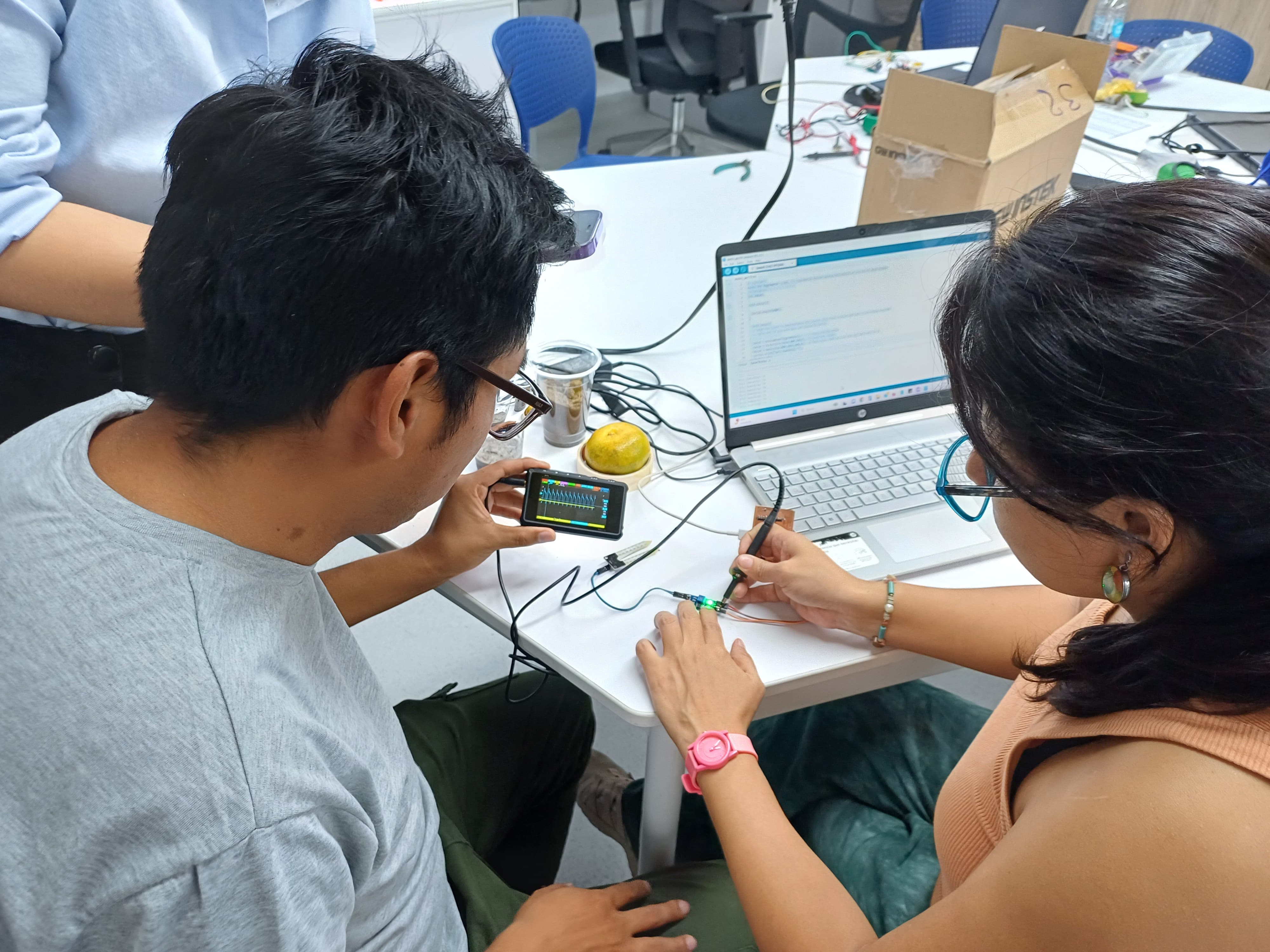
We went to UCSUR (Universidad Cientifica del sur), we all started to see what sensors we have, we saw how they work, each one brought his programming for his sensor and we could do the tests.
Maria Angela was programming the soil moisture sensor, she had many problems with the programming, it took half a day to understand how it worked.
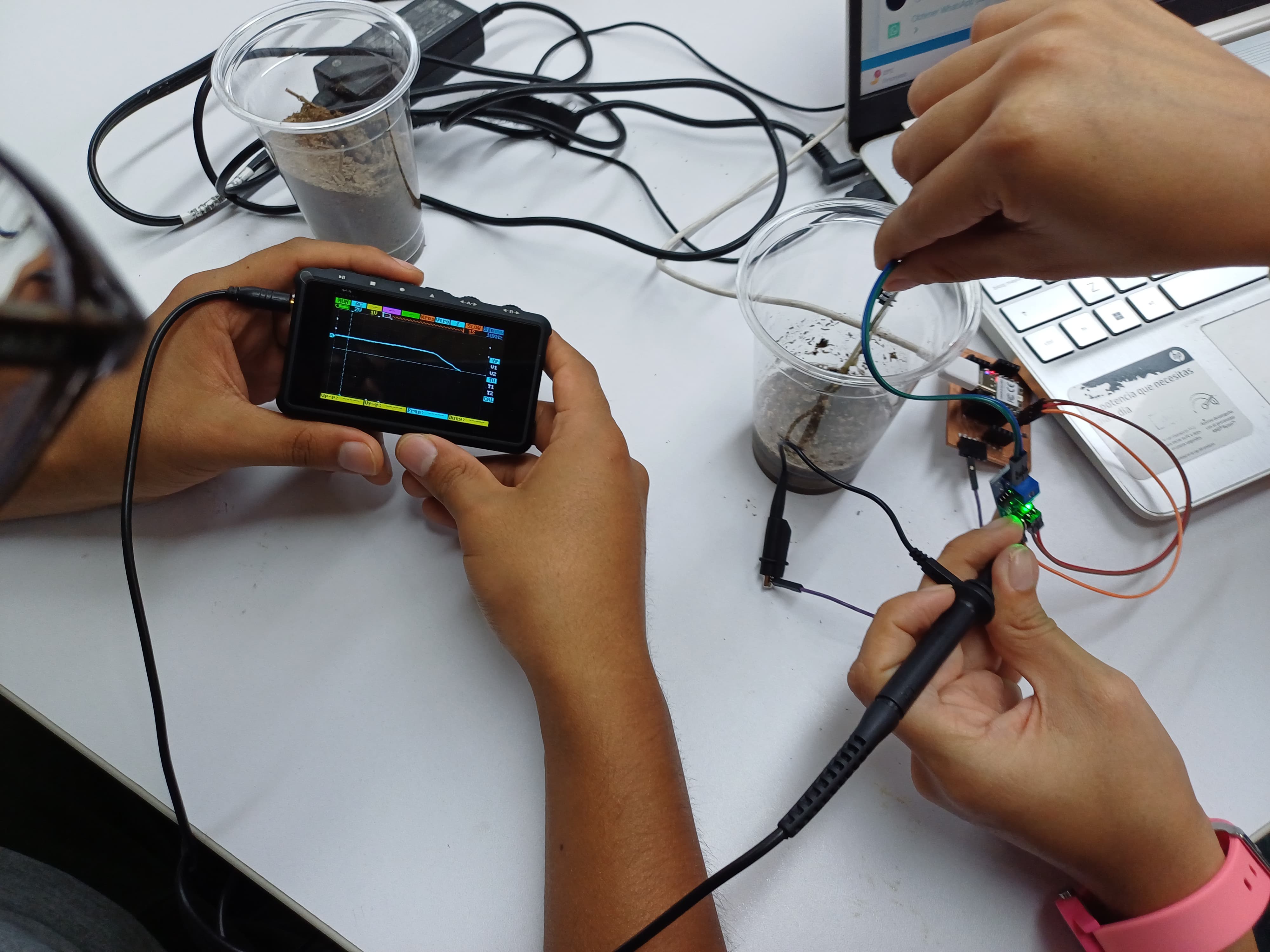
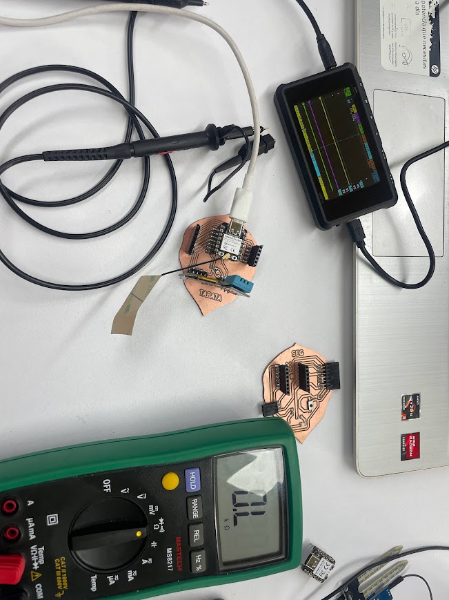
Hans was setting up the oscilloscope to start measuring the sensor signals.
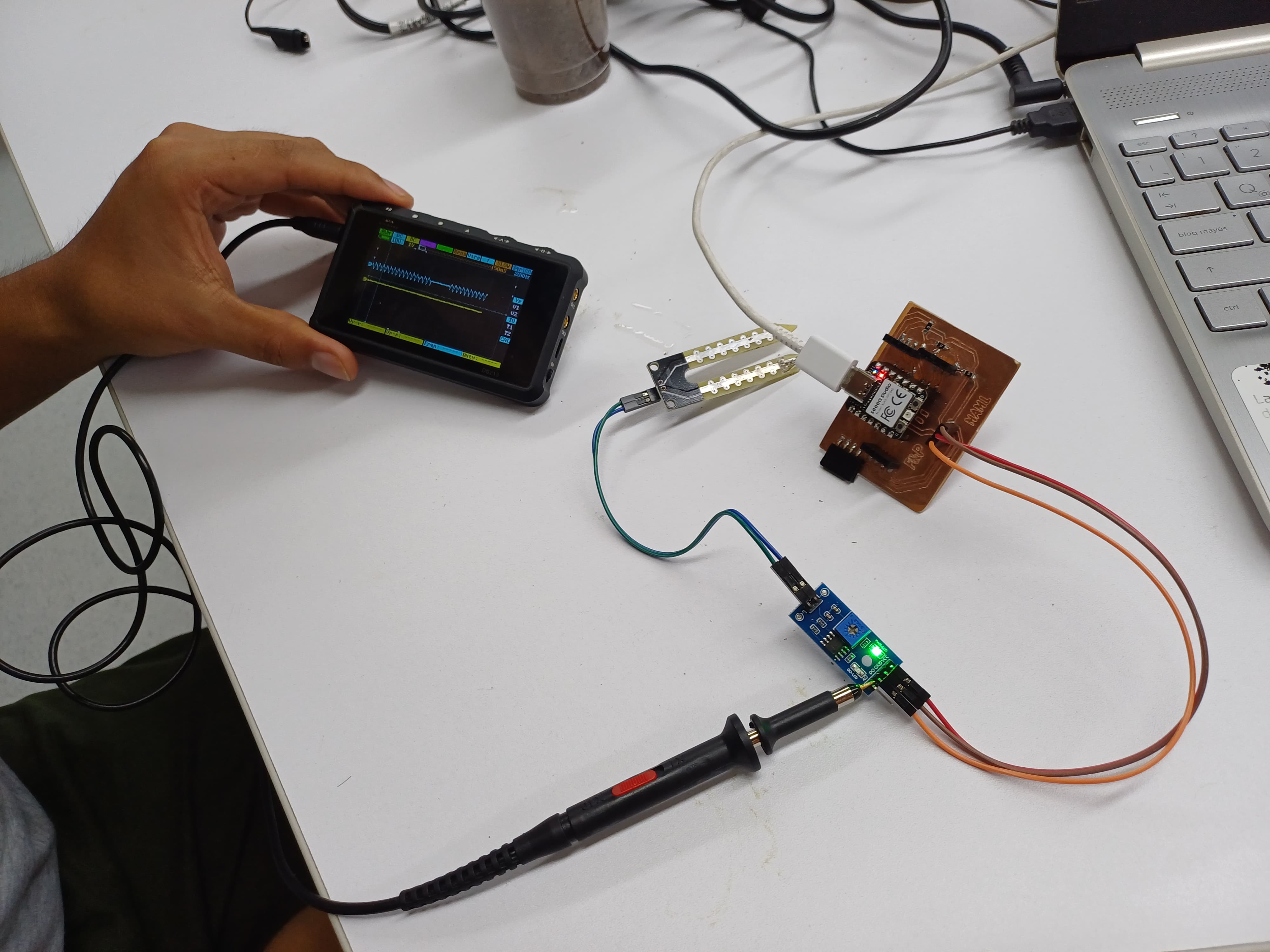
We seek to see the best signal
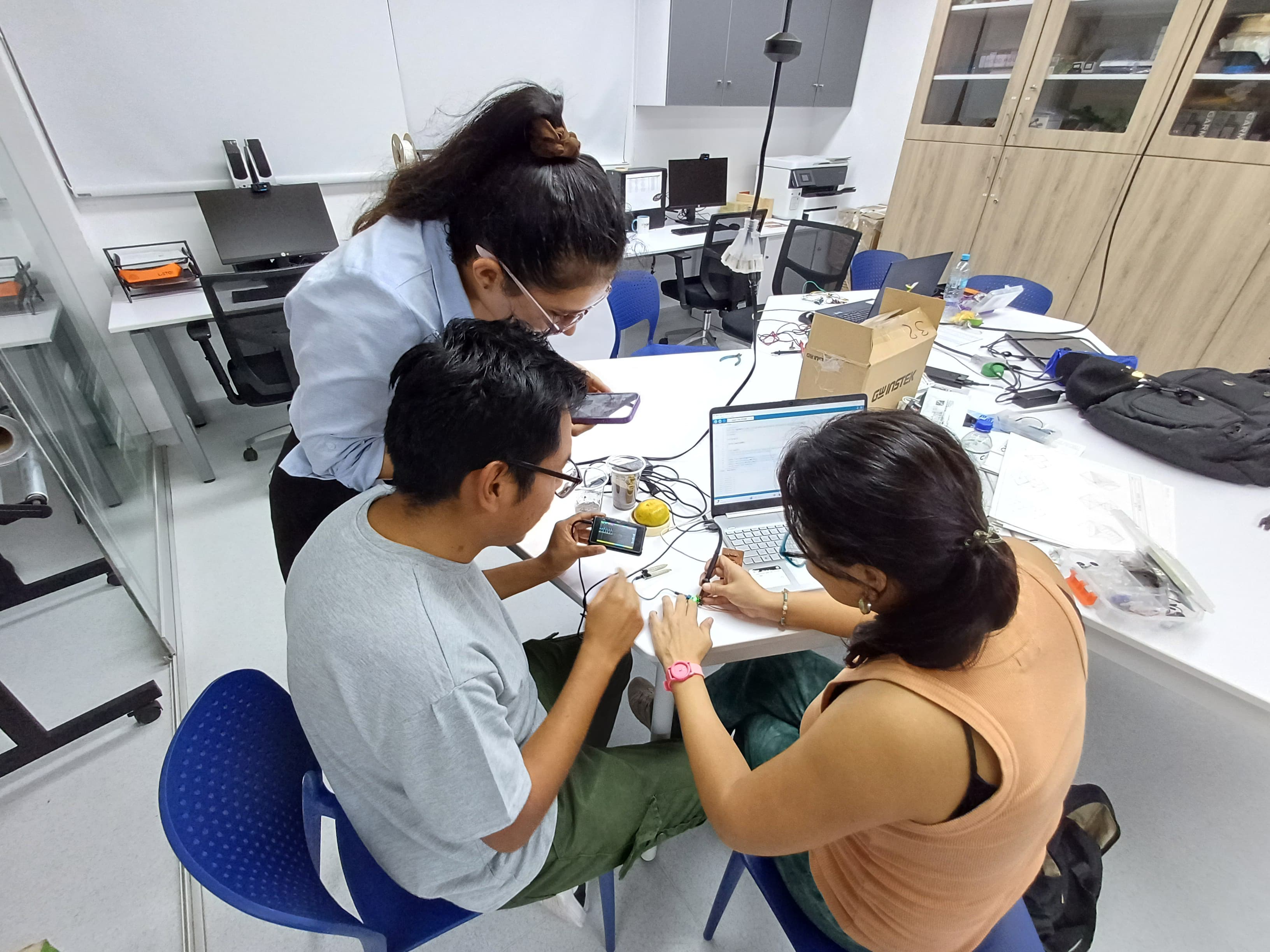
and we were able to have graphs that were within what was expected
Miniware DS213
The Miniware DS213 is a compact portable oscilloscope designed for hobbyists and professionals who require mobility in their projects. With a 3-inch color LCD display, two analog channels, and features such as SD card storage and automatic measurement, it offers a convenient solution for viewing and analyzing signals in the field or in hobby projects. Its portability, combined with basic features and an intuitive user interface, make it an attractive option for low-frequency applications and projects on the move.
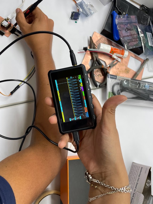
The main thing is to understand how to use the oscilloscope and then obtain accurate measurements. Recently, we performed tests on a servo motor using the Miniware DS213 Portable Mini Oscilloscope. During these tests, we focused on key aspects such as frequency, amplitude and voltage, with the aim of understanding its behavior and verifying its correct operation. Using the oscilloscope, we were able to observe in detail the waveform generated by the servomotor, which allowed us to analyze aspects such as stability, response to different commands and consistency in its operation. This information was invaluable to ensure that the servomotor was operating within the expected parameters and to identify any anomalies that might require attention.
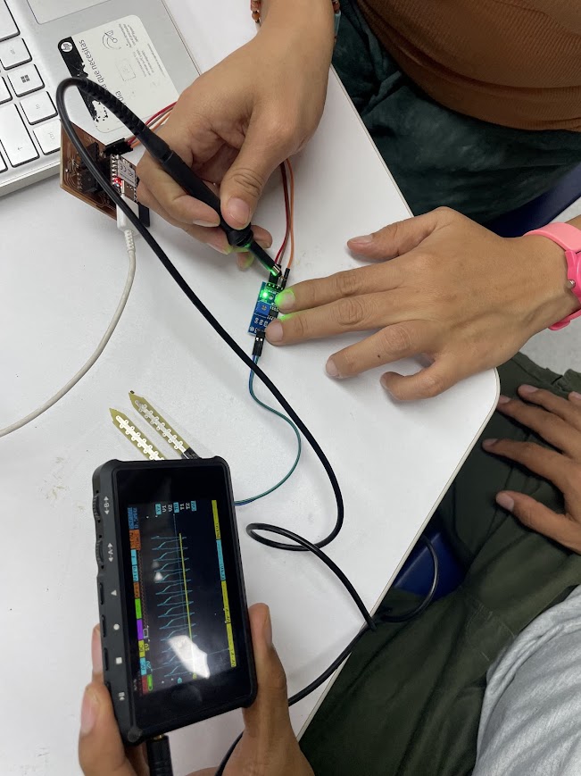
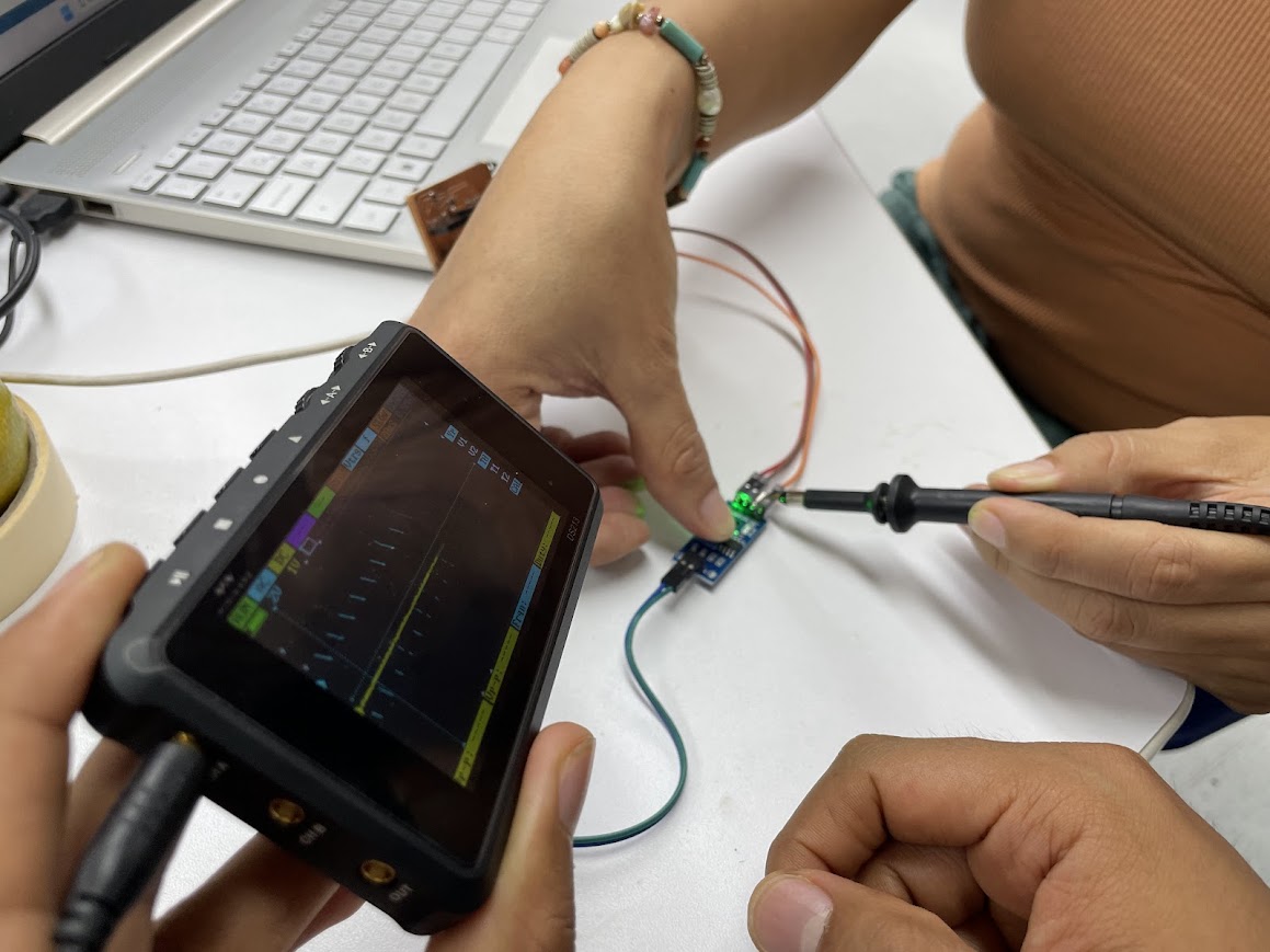
In summary, the use of the oscilloscope allowed us to perform extensive testing and obtain accurate measurements, giving us greater confidence in the quality and performance of the servo motor.
Sensor
The sensor that took the longest to learn to use is this one, really after days I know how to use it and I know that I should no longer put more than 3.3 V on it as it will fail
final result
Conclusions
The MPU6050 combines a 3-axis accelerometer and a 3-axis gyroscope, enabling accurate motion tracking and orientation detection.
With the combination of both sensors, you can develop control systems that respond to changes in environmental conditions or device movement. For example, you could design an automatic irrigation system that adjusts the frequency or amount of water based on soil temperature and device orientation.
The MPU6050 typically operates with a supply voltage of 3.3V or 5V, depending on the specific module you're using and how you're powering it. Most MPU6050 modules have an onboard voltage regulator that allows them to operate over a wide range of input voltages.
While the MPU6050 can operate with both 3.3V and 5V supply voltages, it's often recommended to use 3.3V to avoid potential damage to the sensor, especially if you're interfacing it with other components that operate at 3.3V.
It is crucial to install the library correctly because it provides predefined functions and methods that simplify communication with the DHT sensor. This includes reading temperature and humidity data accurately and efficiently. In addition, the library handles the complexity of communicating with the sensor, allowing me to focus on the logic of my program without worrying about low-level details.