Machine Week
Week 10 - Mechanical Design | Machine Design
Mechanical design Group assignment:
- Design a machine that includes mechanism+actuation+automation+application
- Build the mechanical parts and operate it manually
- Document the group project and your individual contribution
Machine design Group assignment:
- Actuate and automate your machine
- Document the group project and your individual contribution
Group 1
Group 2
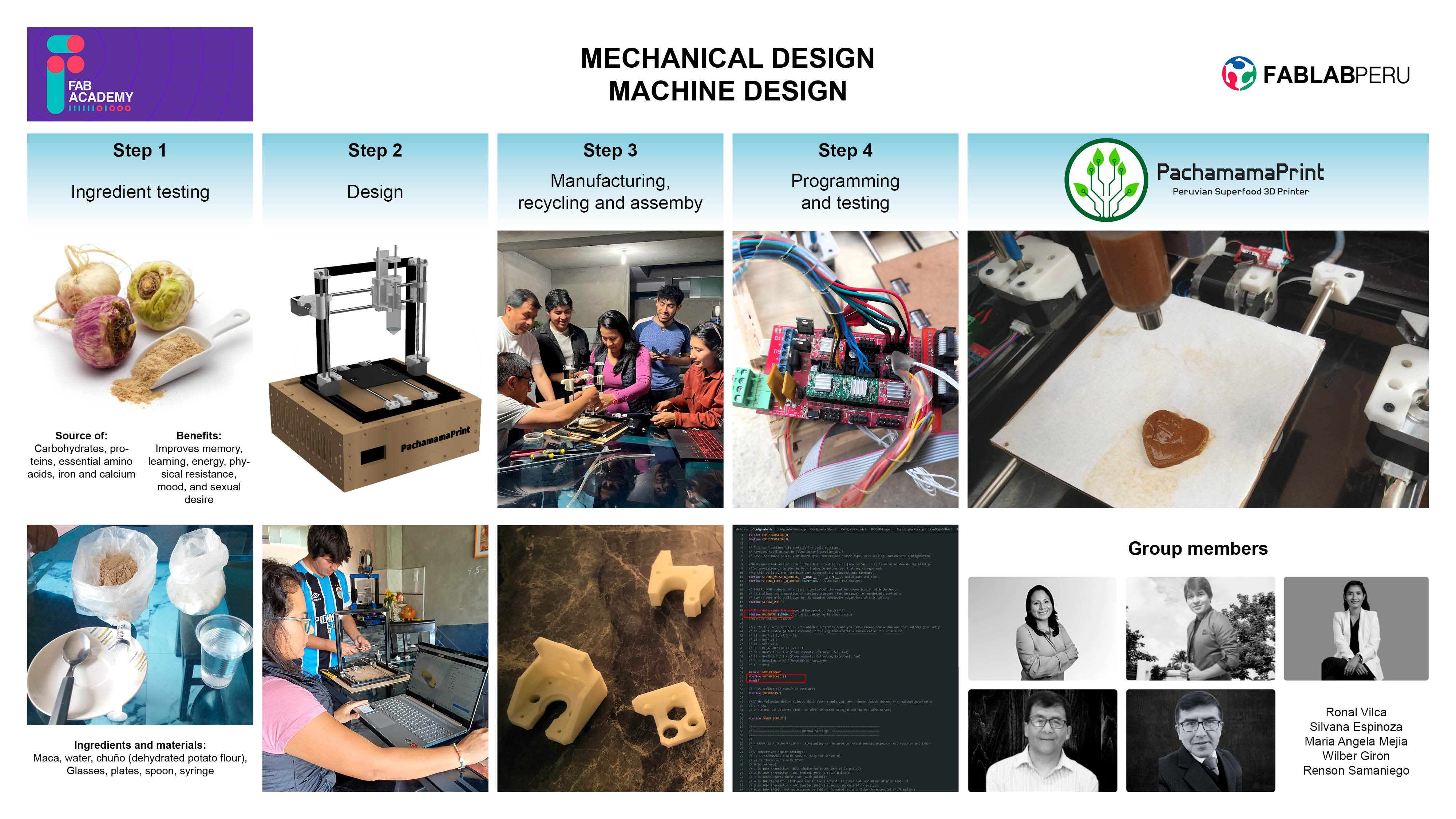
Group 1: PACHAMAMA PRINT
Inspiration
Drawing inspiration from our Peruvian heritage and a deep concern for the health of our community, our team embarked on a journey fueled by the vibrant tapestry of our culinary traditions and a desire to address the nutritional challenges faced by many, particularly children, within our country. In Peru, we are blessed with a rich array of indigenous superfoods like maca, yet despite their nutritional potency, their appeal often falls short, especially among younger generations.
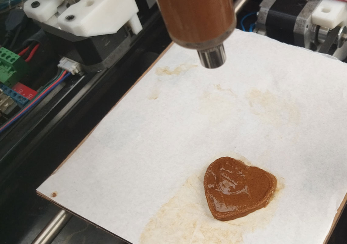
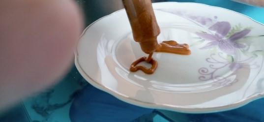
Witnessing firsthand the adverse effects of poor dietary habits on the well-being of our people, particularly the prevalence of health issues among children due to inadequate nutrition, we felt compelled to innovate. Thus, the idea of PachamamaPrint was born— revolutionary superfood 3D printer designed to transform maca,a and potentially other nutritious ingredients, into enticing and visually appealing culinary creations. Our inspiration stemmed from a dual commitment: to celebrate the bounty of our land and to address the pressing need for accessible, nutritious food options that resonate with diverse palates, ultimately fostering a healthier future for our community.
Material testing
BIOMATERIAL TEST IN MACA

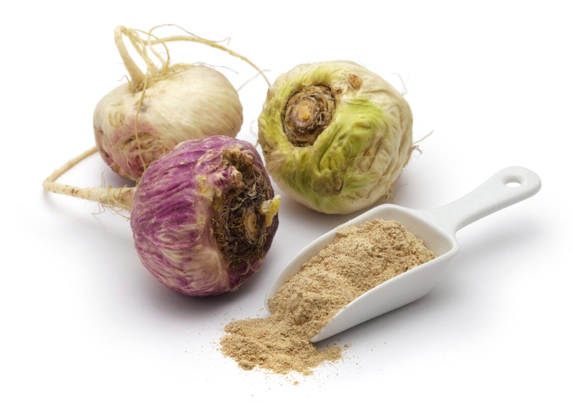
NUTRITIONAL COMPONENTS OF MACA
The results of the chemical composition of the extruded black maca flour were protein 11.62% and ash 4.28%, highlighting its iron content 30.71 mg/100g and essential amino acids such as lysine, valine, threonine, leucine, isoleucine and arginine
WHY DO WE USE MACA?
It is a tuber of Andean origin and has various health properties.
MATERIALS TO BE USED FOR THE MACA CONSISTENCY TEST
| Materials | Quantity | Cost |
|---|---|---|
| Junin maca in pre-cooked powder | ¼ Kg | 3 PEN |
| 20 ml syringe | 2 Unit | 1.5 PEN |
| Disposable cups | 10 | 1 PEN |
| Chuño | ¼ Kg | 2 PEN |
| 7.50 | ||
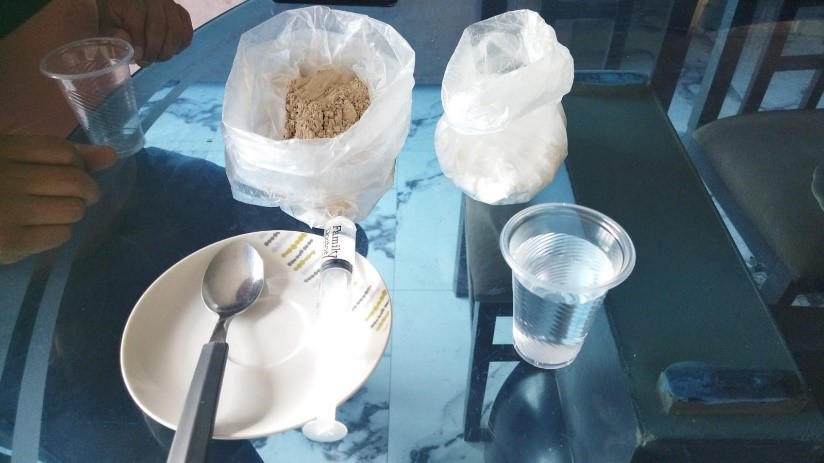
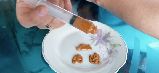
PROCEDURE
Pour water and pour water, maca, chuño and stir with a spoon, according to the following details:
| EVIDENCE | WATER | BRUISE | CHUÑO | TIME | RESULT |
|---|---|---|---|---|---|
| EVIDENCE 001 | 10 ml | 10 gr | 5 gr | 10 min | watery |
| EVIDENCE 002 | 10 ml | 12 gr | 10 gr | 10 min | watery |
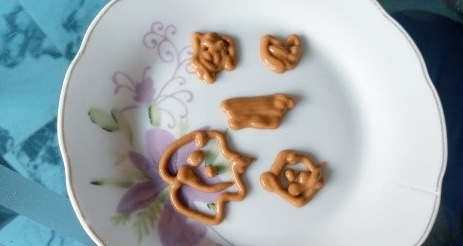
| EVIDENCE 003 | 20 ml | 30 gr | 0 gr | 10 min | It is done in 3 layers and is consistent |
| 100.00 | |||||
Placing the calibrator
Correctly arranging the MDF cutting material so that all sides
Placing the calibrator
Correctly arranging the MDF cutting material so that all sides
Placing the calibrator
Correctly arranging the MDF cutting material so that all sides
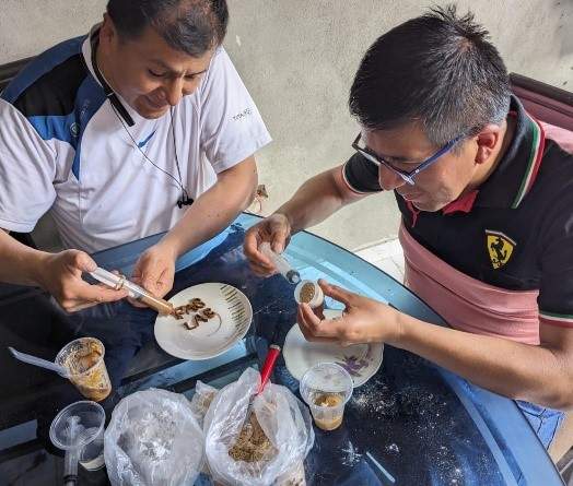
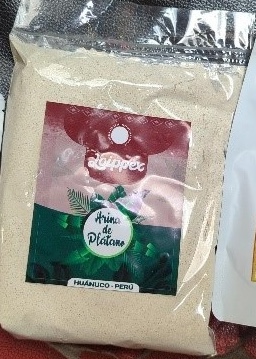
BIOMATERIAL TEST IN GREEN BANANA
Prototype Construction
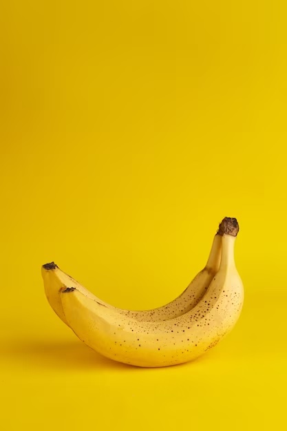
SCIENTIFIC NAME = Musa Paradisiaca
Bananas are a source of minerals such as magnesium, iron, manganese and potassium, which are very important for the maintenance of our muscles, as well as for keeping blood pressure stabilized.
NUTRITIONAL COMPONENTS OF BANANAS
Fiber, potassium, vitamin B6 and inulin. Bananas barely contain proteins (1.2%) and lipids (0.3%), although their content in these components exceeds that of other fruits. Its composition highlights its richness in carbohydrates (20%)
WHY DO WE USE BANANAS?
It is a fruit widely used in the Huánuco area and has nutritional components.
MATERIALS TO BE USED FOR THE MACA CONSISTENCY TEST
| Materials | Quantity | Cost |
|---|---|---|
| Junin maca in pre-cooked powder | ¼ kilo | 3 PEN |
| 20 ml syringe | 2 Unit | 1.5 PEN |
| Disposable cups | 10 | 1 PEN |
| Chuño | ¼ Kilo | 2 PEN |
| 7.50 | ||
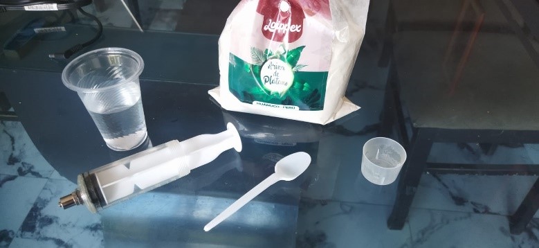
PROCEDURE
Add water and banana flour and stir with a spoon, according to the following details:
| EVIDENCE | WATER | BRUISE | CHUÑO | TIME | RESULT |
|---|---|---|---|---|---|
| EVIDENCE 001 | 10 ml | 20 gr | 30 gr | 10 min | consistent |
Design
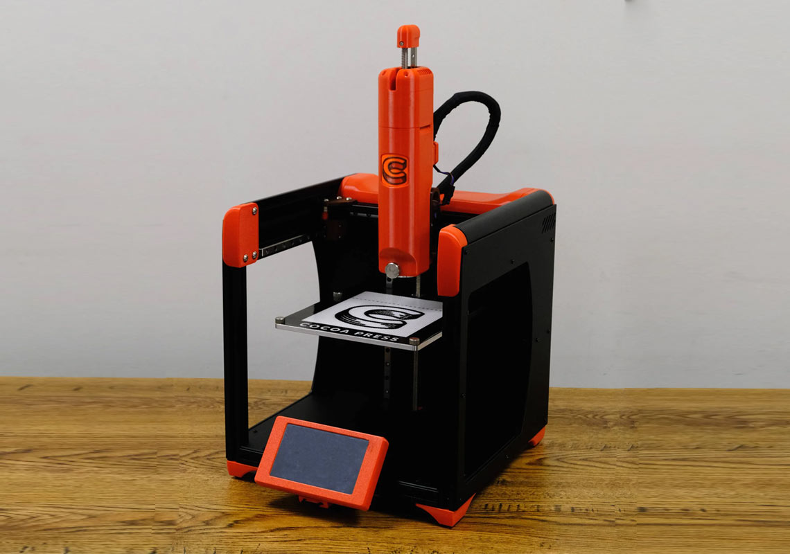
In the initial phase of designing PachamamaPrint, I delved into the realm of existing 3D food printers, particularly those specializing in chocolate, scouring the market for inspiration. Observing their forms and functionalities, I began sketching out preliminary designs, envisioning a cubic structure that would provide stability and practicality for our intended purpose. Taking cues from the sleek, streamlined shapes of contemporary food printers, I aimed to marry functionality with aesthetics, ensuring that our machine would not only be efficient but also visually appealing.
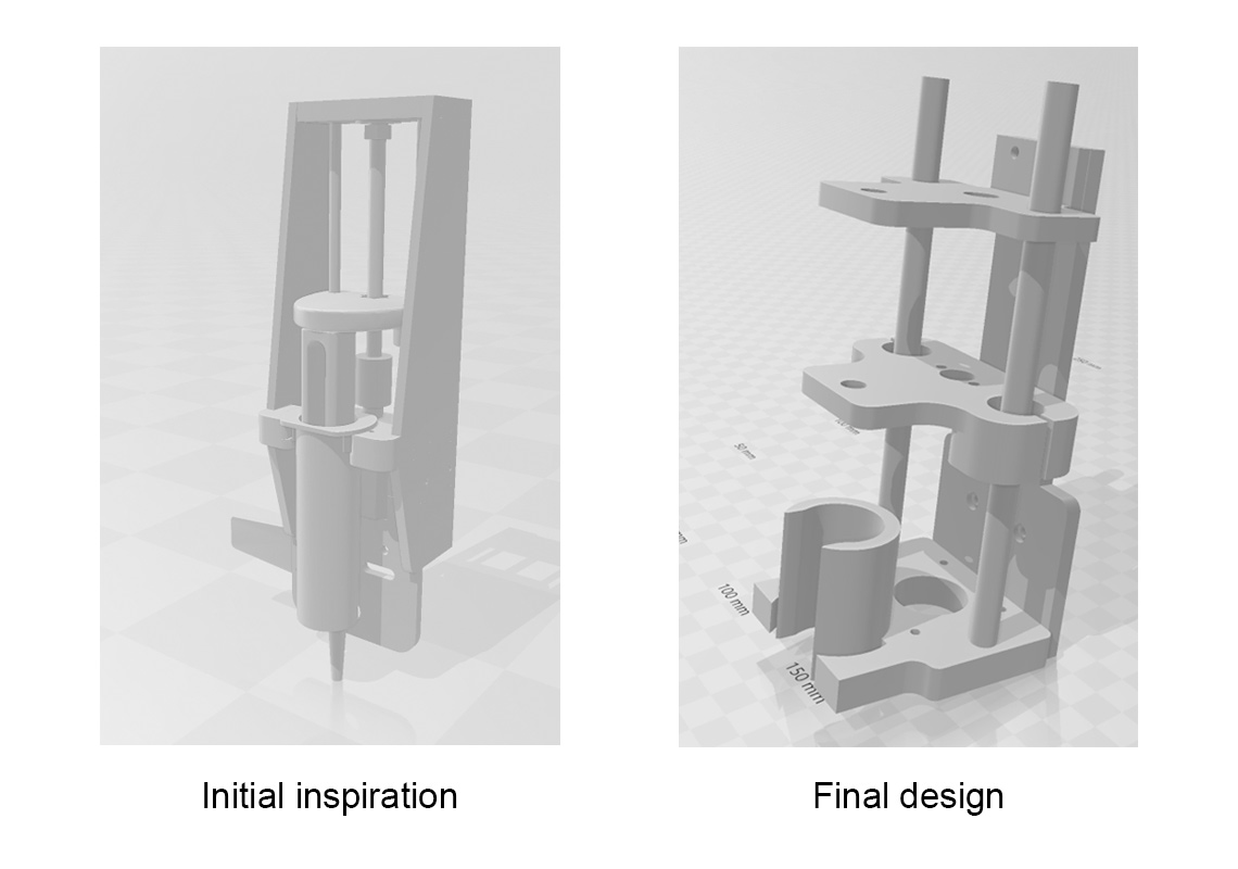
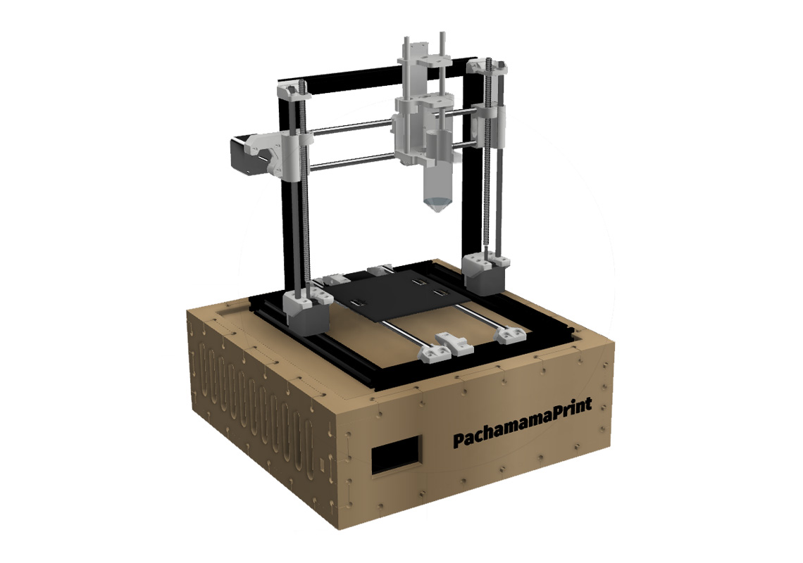
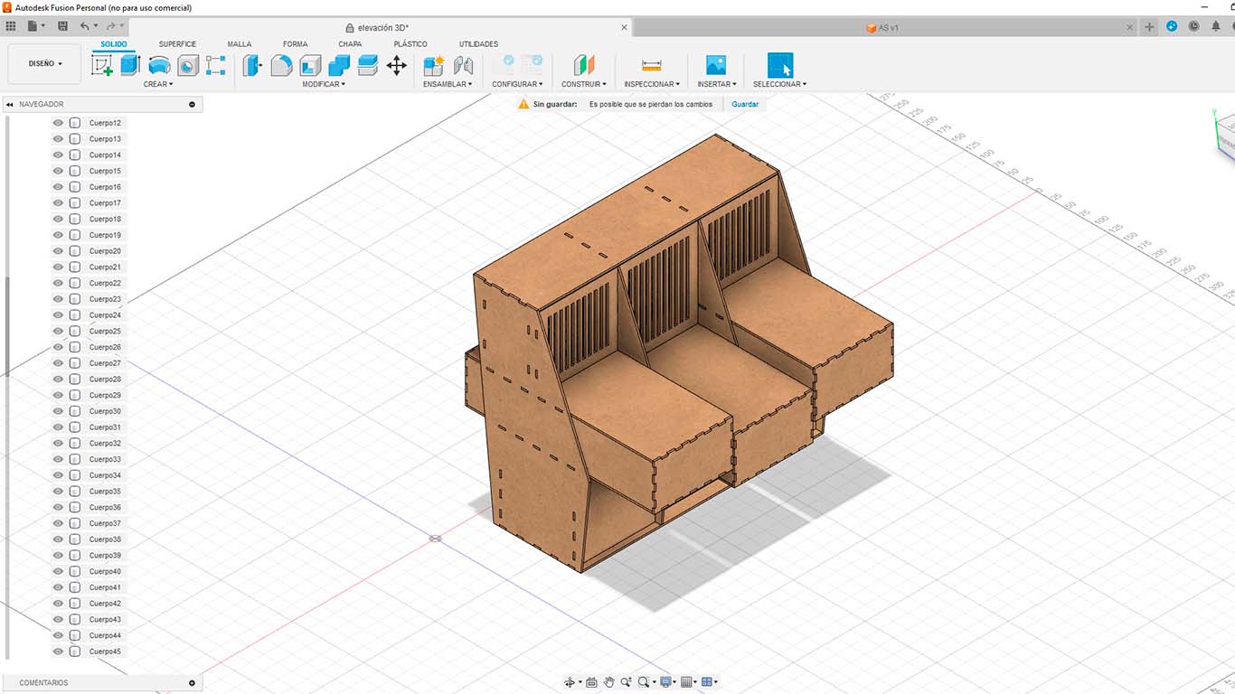
Transitioning from conceptual sketches to tangible designs, I turned to Fusion 360, a powerful CAD software, to bring my ideas to life. Drawing upon components from existing 3D printers, I meticulously crafted each element with precision, seeking to optimize performance and ease of use. Through iterative modeling and refinement, I created a digital prototype of PachamamaPrint, complete with intricate details and realistic textures. Rendering the design allowed me to visualize the final product, refining it further based on feedback and feasibility considerations.

As our team progressed, we encountered the crucial challenge of adapting our design to accommodate the unique properties of maca and the extrusion process. Collaborating closely with colleagues who conducted ingredient testing, I focused on refining the extrusion component to ensure seamless integration with our chosen superfood. Iterating through various designs and material compositions, we fine-tuned the extrusion mechanism to achieve optimal results, balancing precision with reliability to guarantee consistent output.
In hindsight, the journey of designing PachamamaPrint was not without its obstacles. Despite our meticulous planning and attention to detail, we encountered unforeseen challenges along the way as described. However, each setback served as a learning opportunity, prompting us to reassess our approach and implement innovative solutions. Through perseverance and collaborative effort, we overcame adversity, ultimately realizing our vision of creating a transformative tool for promoting healthier eating habits and fostering a brighter future for our community.
Manufacturing, recycling and assembly
Manufacturing
With the designs finalized, the next step was to bring them into the physical realm through 3D printing. Utilizing Ultimaker Cura slicer software, I prepared the digital models, generating the necessary G-codes to instruct the printer.
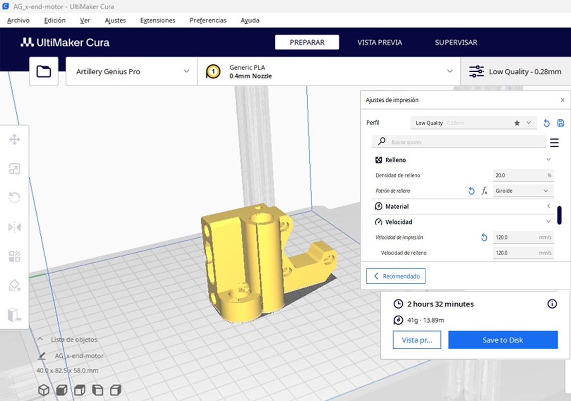
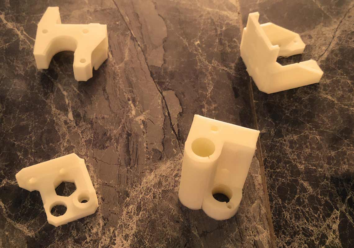
Turning to the Artillery Genius Pro 3D printer, I carefully calibrated the settings and loaded white PLA filament, ensuring optimal print quality. Over the course of several printing sessions (almost a full day), the machine diligently fabricated each component.
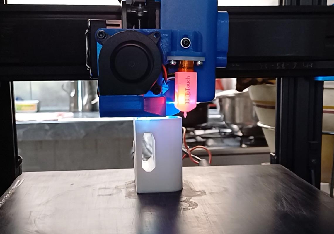
Through constant monitoring and adjustment, I maintained strict quality control, striving for flawless execution in every print.
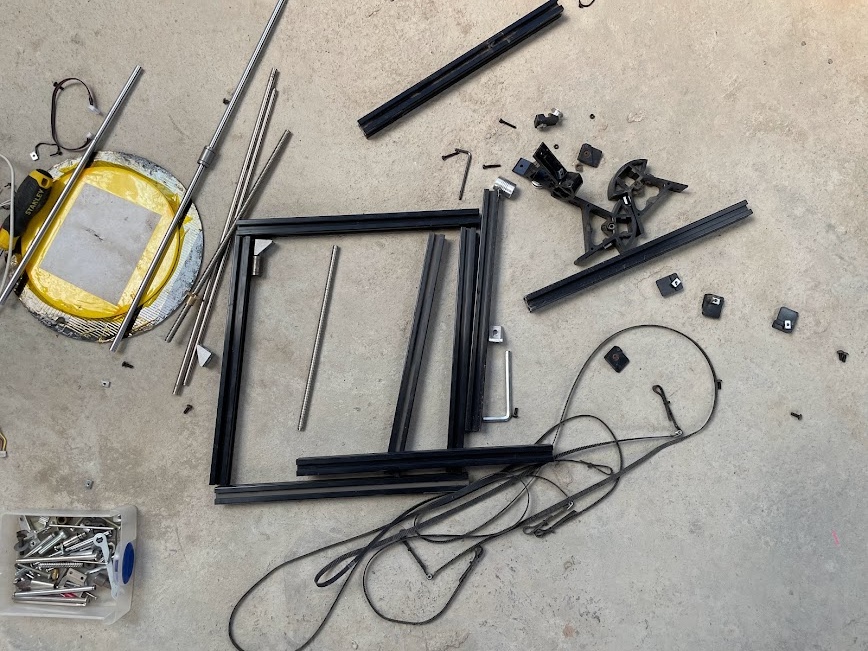
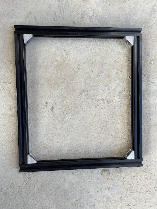
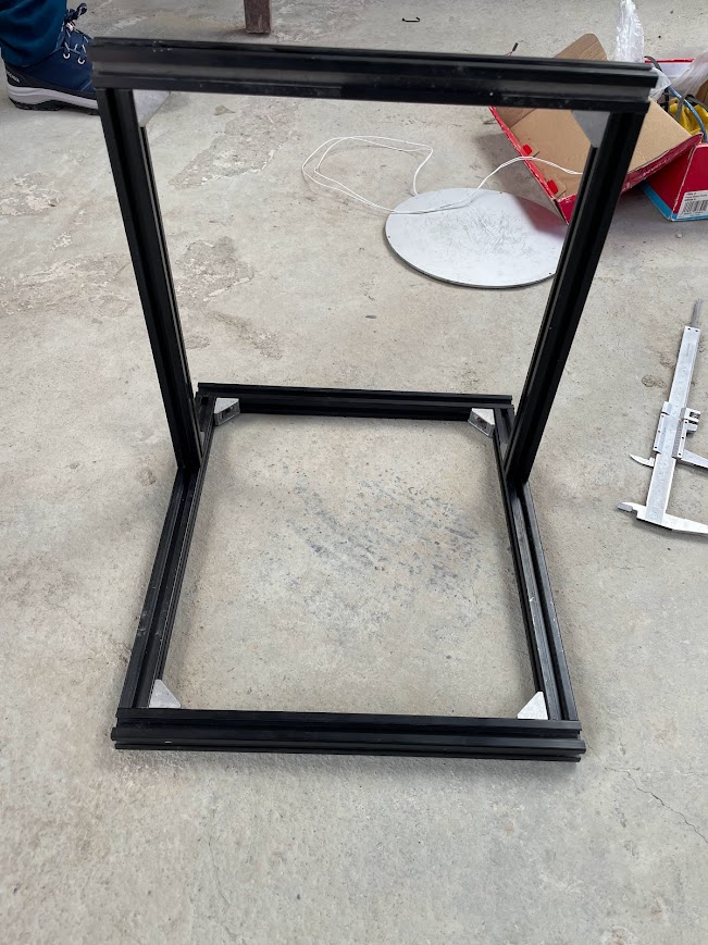
I did not manufactured a entire new structure because our team adopted a sustainable approach by repurposing components from a disused machine. Recognizing the value of recycling and minimizing waste, we meticulously salvaged and refurbished suitable parts, integrating them seamlessly into our design. This eco-conscious decision not only reduced our environmental footprint but also demonstrated our commitment to responsible machine building practices. By repurposing existing materials, we breathed new life into discarded components, transforming them into integral elements of PachamamaPrint, further embodying our ethos of innovation, sustainability, and community stewardship.
Recycling
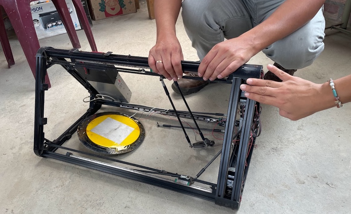
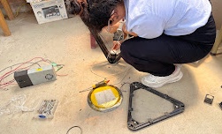
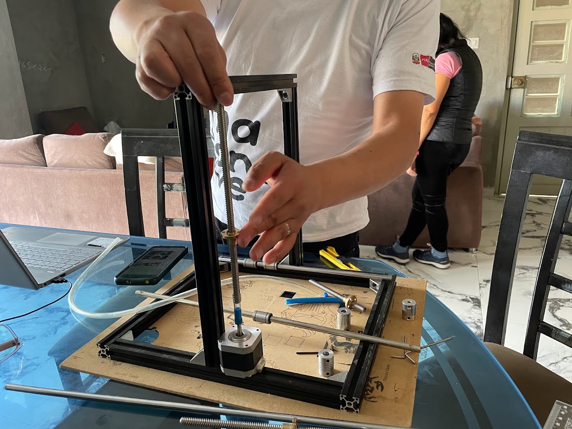
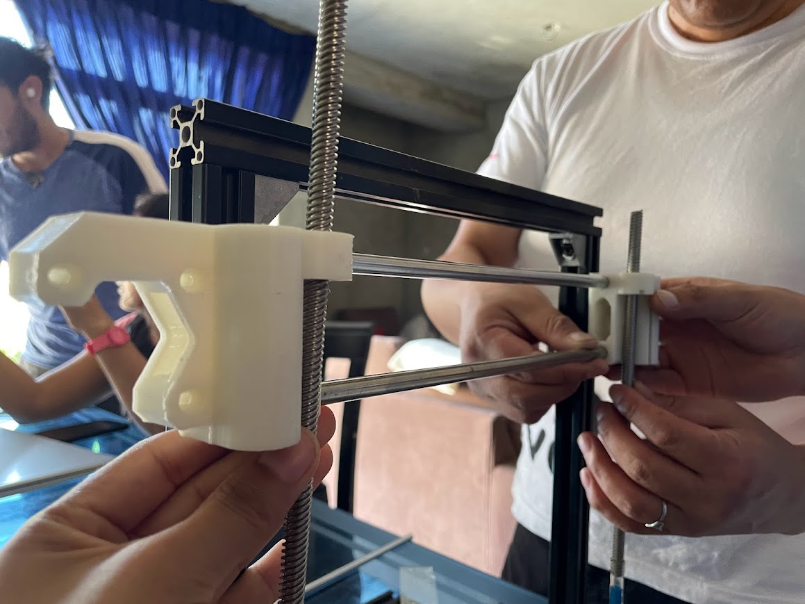
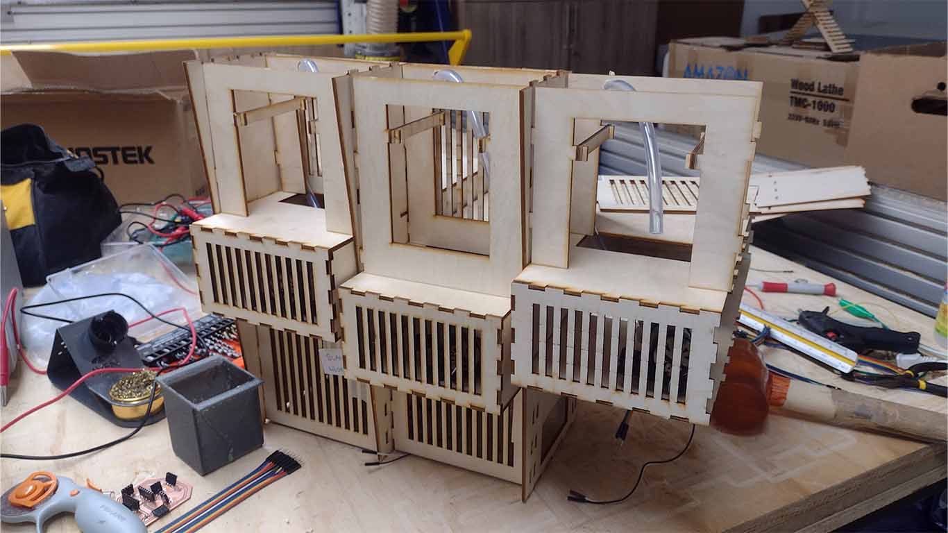
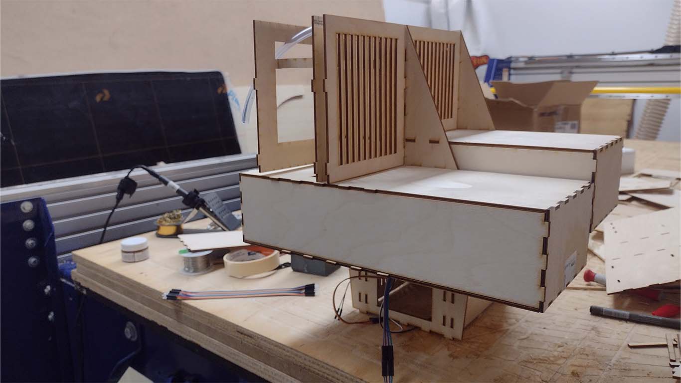
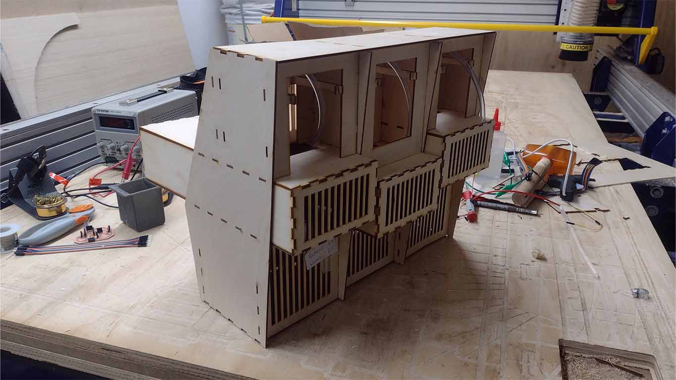
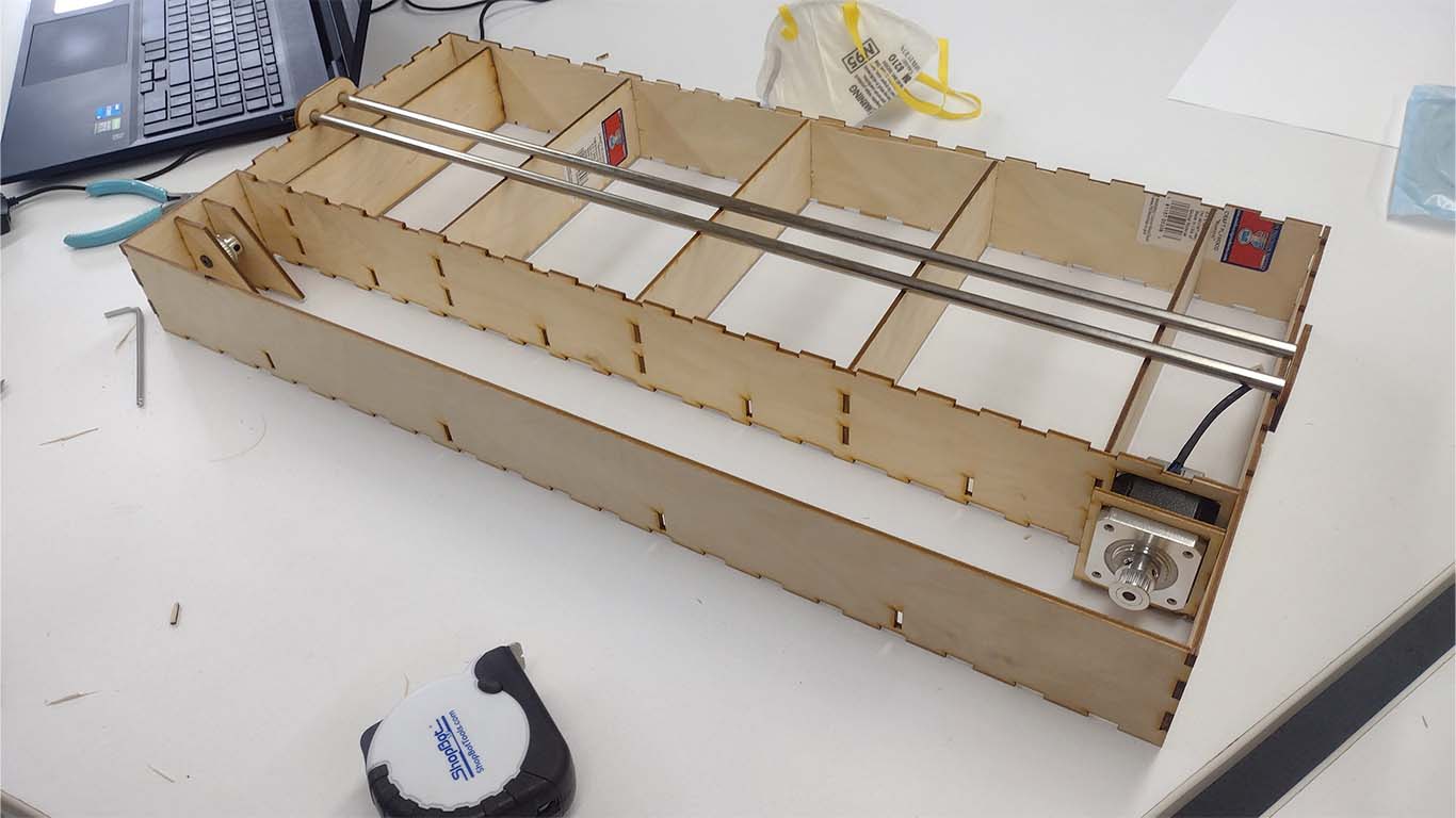
Prototype Construction
We began the exciting task of manufacturing a machine. For this activity, María Ángela and I moved to Huánuco, which is approximately 10 hours from Lima, with the purpose of working as a team with Ronald, Renso and Wilmer. Together, we brought the materials and supplies necessary to build the machine we had previously designed. In addition, Franco accompanied us on the trip and helped us with the acrylic necessary for the machine's casing.
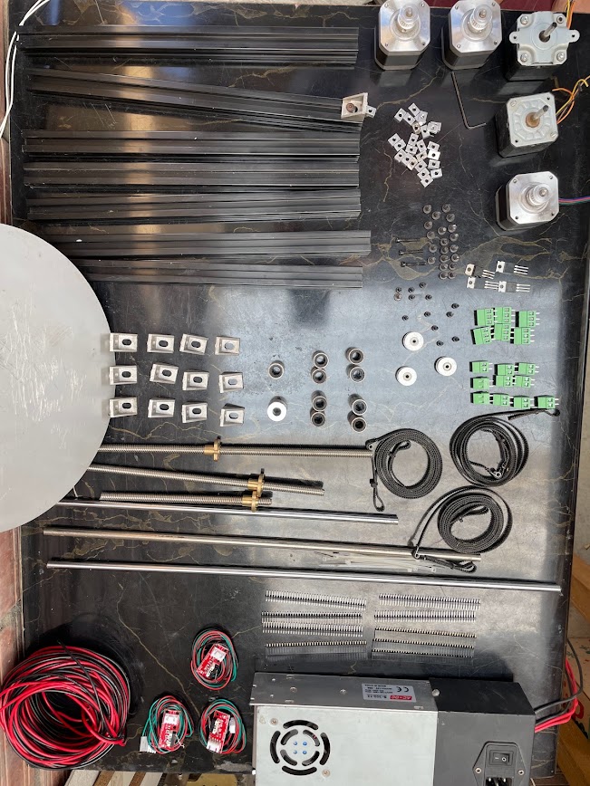
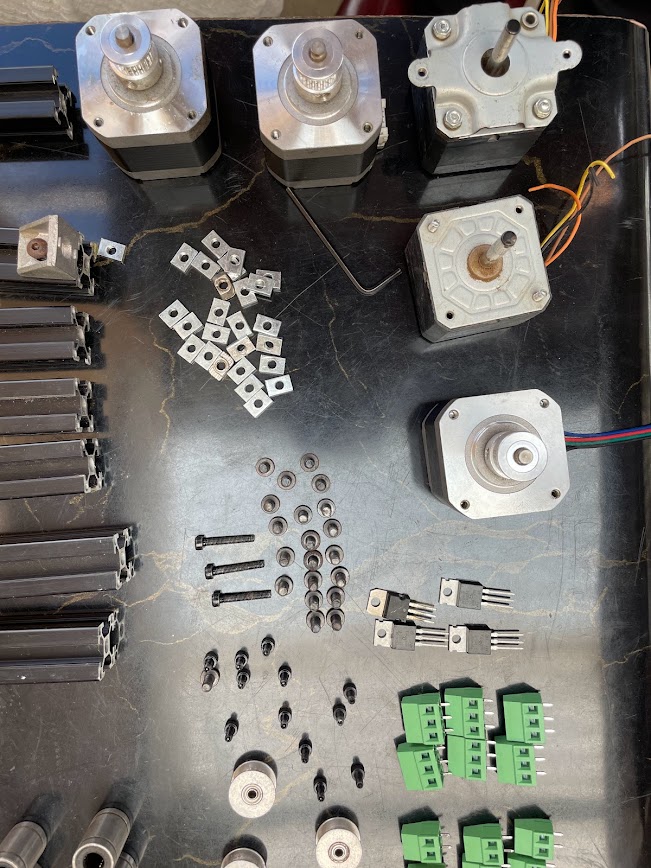
Material
- 2 M8 Z axis threaded rods
- 3 Nut T8
- V-SLOT PROFILE 20X20x300
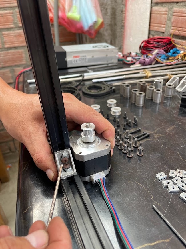
- 2 GT2 timing belt half meter 6mmx1M X and Y axis
- 2 GT2 toothed pulley 22 teeth M5 motor for the X and Y axis
- 2 GT2 22 smooth toothed pulley M5 X and Y axis
- 6 smooth M8 rods of 30 cm Y, Z and X axis
- Working temperature: -30ºC ~ 70ºC
- 10 M8 linear bearings
- 1 M8 threaded rod for the extruder
- 8 90 degree angles per 20 mm
- 3 Flexible couplings M5xM8
- 1 Flexible coupling M8xM8 15 soles Nuts and bolts
- 100 SLIDING HAMMER HEAD NUT M5 (order more, they will be lost)
- 40 M3 engine bolts
- 100 M5 screws Electronic
- Arduino Mega
- 3D Printer Controller Board RAMPS 1.4 Arduino Mega Shield
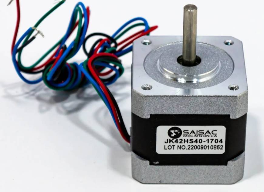
- 5 Stepper motor NEMA 17 42x39mm 4.2Kg
- 2 100k thermistors (to see the temperature at which material is worked in the environment)
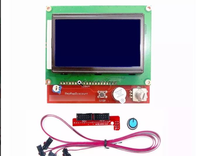
- 1 Lcd Graphic 128x64 Shield Ramps 1.4 3d Printer
- 5 Cable for stepper motor, 1 meter long, 4 wires, with HX254 Female
- Inputs for motor (Nema 17)
- 12V and 20A power supply with power cable
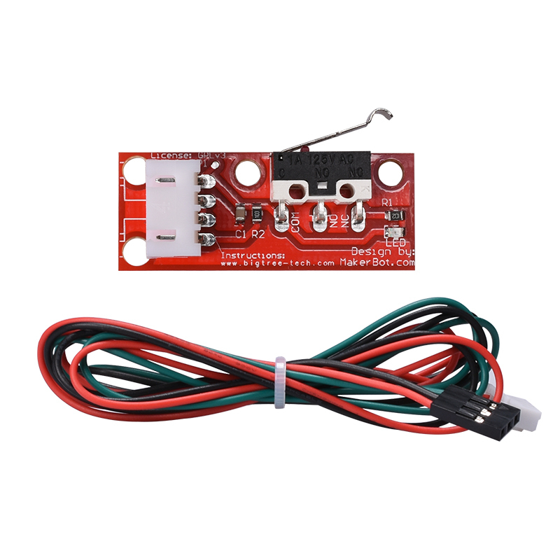
- 3 Limit Switch Module for 3D Printer
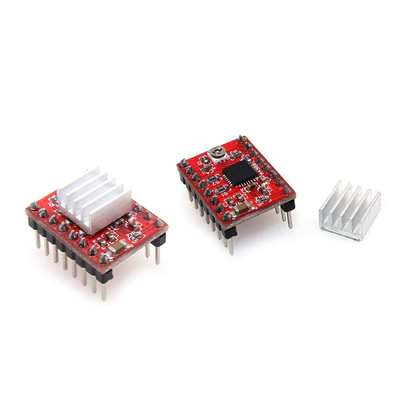
- A4988 Stepper Motor Driver Module for Pololu

Placing the calibrator
Placing the calibrator
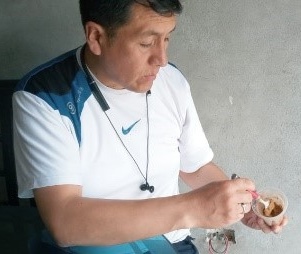
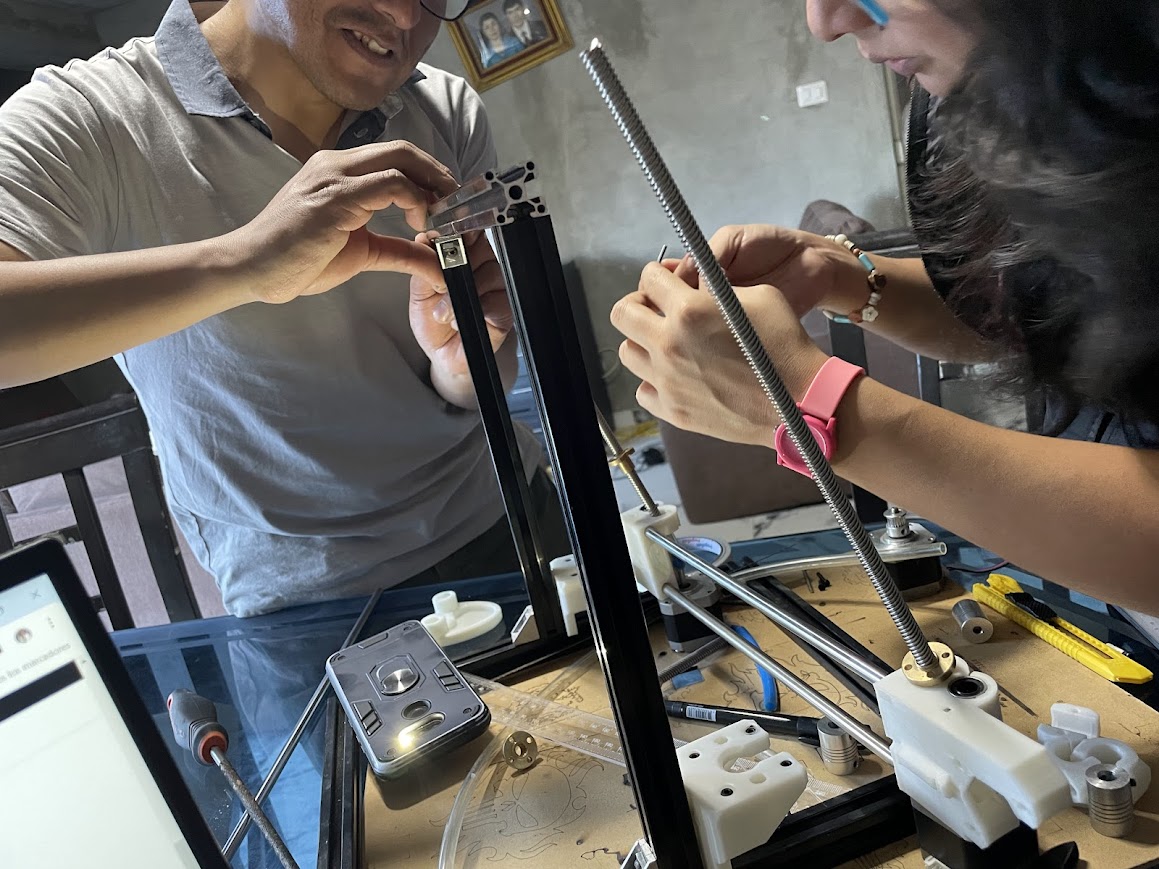
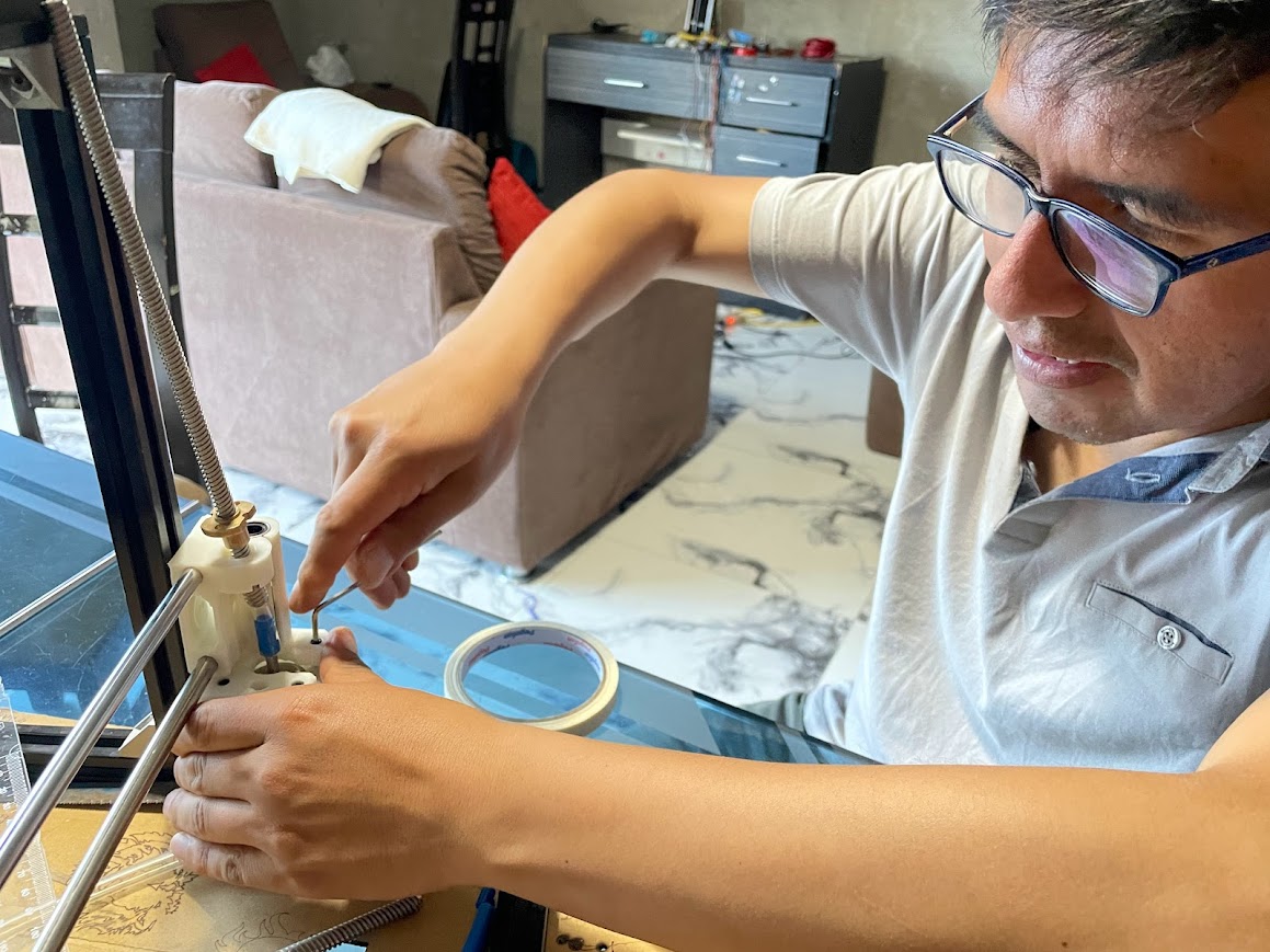
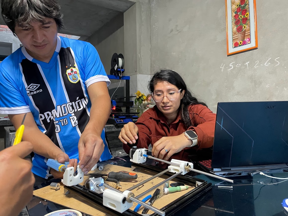
Working with my Fab Academy colleagues for the first time in person was very interesting. Each one shared their digital manufacturing experiences and we spent a nice friday afternoon.
recycling
Placing the calibrator
Correctly arranging the MDF cutting material so that all sides
Placing the calibrator
Correctly arranging the MDF cutting material so that all sides
Placing the calibrator
Correctly arranging the MDF cutting material so that all sides
Placing the calibrator
Correctly arranging the MDF cutting material so that all sides
Placing the calibrator
Correctly arranging the MDF cutting material so that all sides
Placing the calibrator
Correctly arranging the MDF cutting material so that all sides
Assembly
Having defined the machine, the crucial moment arrived to select the hardware that will give life to our project. This step is essential, since the appropriate choice of components will determine the performance, reliability and efficiency of our machine. We are committed to opting for quality hardware that meets our technical specifications and ensures optimal performance over time.
3D Printer Hardware
- Atmega2560
- Atmega 644.
We are considering two microcontroller options for our machine, based on their capacity and layout. This decision is crucial to ensure efficient and reliable operation. We are carefully evaluating both options before making a final decision.
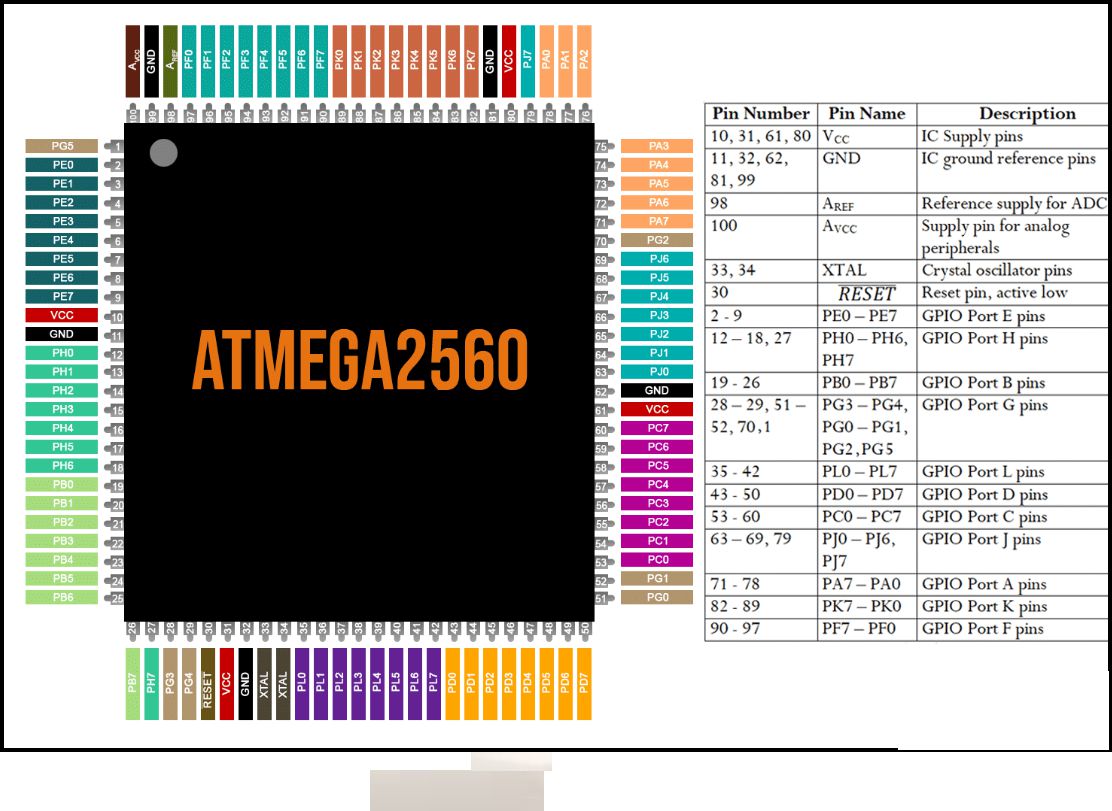
ATMega2560 Pinout Configuration
Features and Specifications
- 86 programmable IO lines
- Two 8-bit timer/counters, four 16-bit timer/counters
- 16-channel 10-bit ADC
- Four USART
- SPI serial interface
- On-chip analog comparator
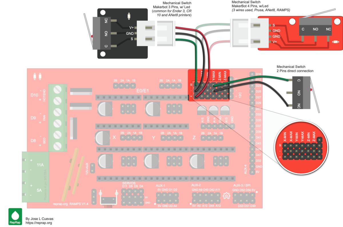
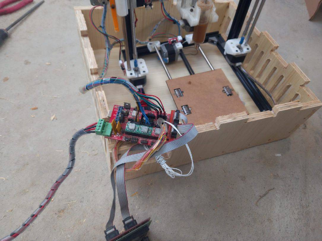
RAMPAS 1.4
RAMPS 1.4 is probably the most widely used electronics for RepRap machines as of March 2014. It consists of a RAMPS 1.4 shield, an Arduino Mega 2560 board (or a clone), and a max of five Pololu Stepper drivers. It can control up to 5 stepper motors with 1/16 stepping precision and interface with a hotend, a heatbed, a fan (or a second hotend), a LCD controller, a 12V (or 24V with appropriate modification) power supply, up to three thermistors, and up to six end stoppers.
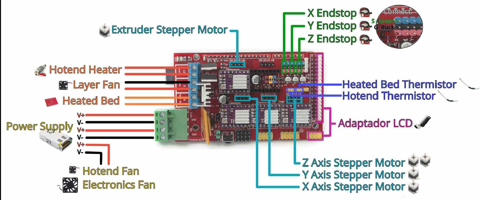
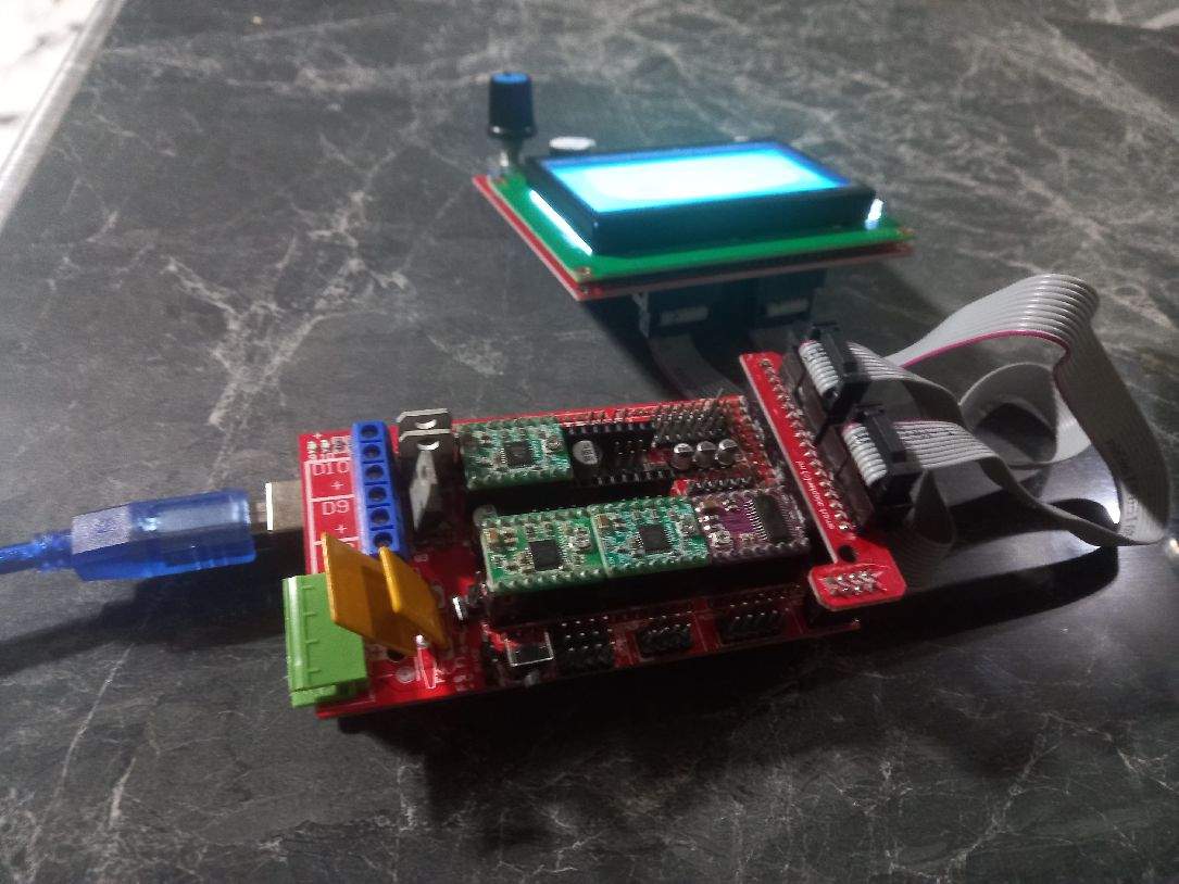
With the Ramps 1.4 board in our hands and the necessary components ready, it is time to proceed with its installation following both the image provided and the detailed instructions on the website.
Necessary components
- 1 Ramps 1.4
- 1 Mega2560.
- 12 Yamper.
- 4 Driver A4988.
- 1 Graphic LCD 128x64.
- 4 Nema 17 motors at 0.7 amp.
- 3 career endings.
- 1 Thermistor.
- 1 12 VDC source at 20 Amp.
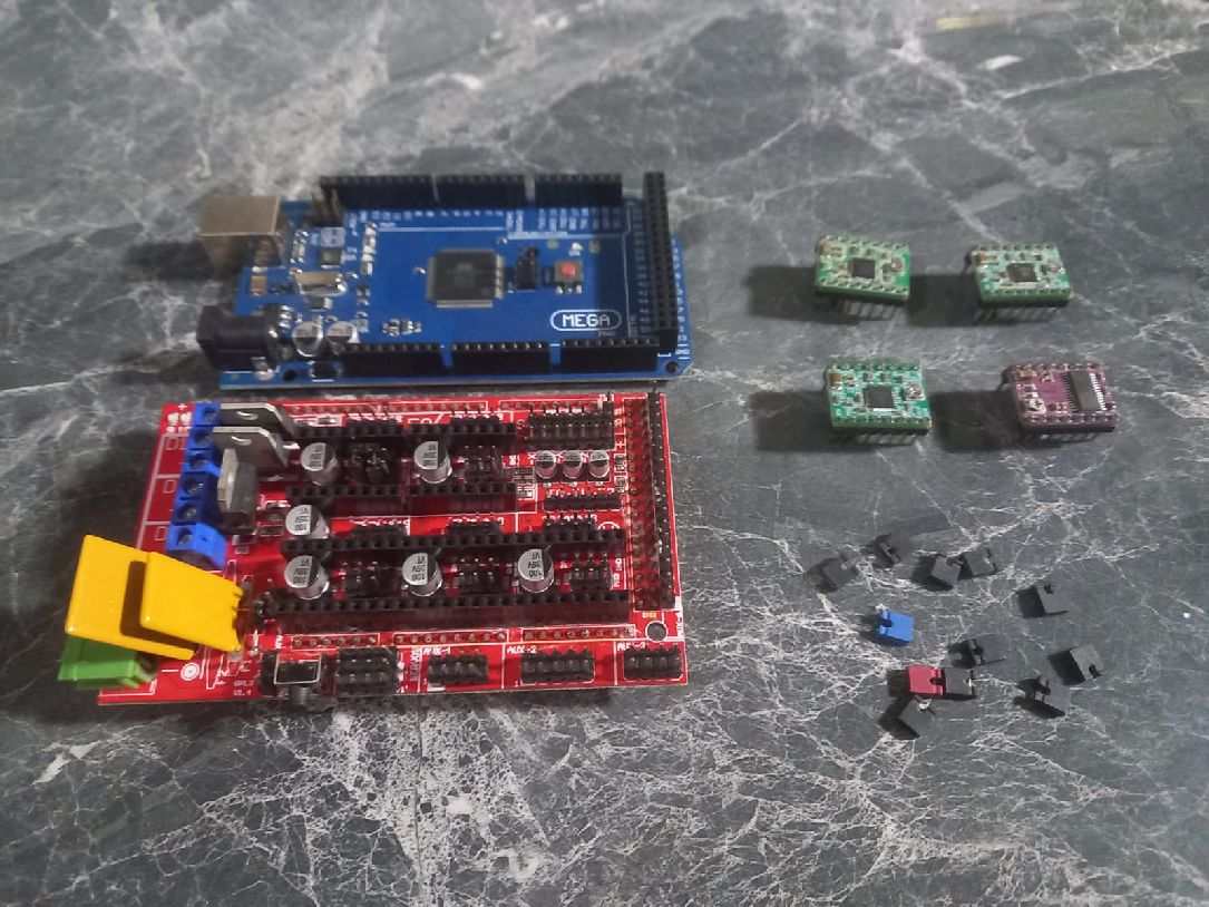
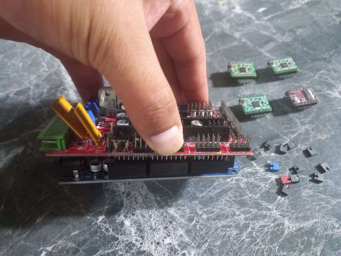
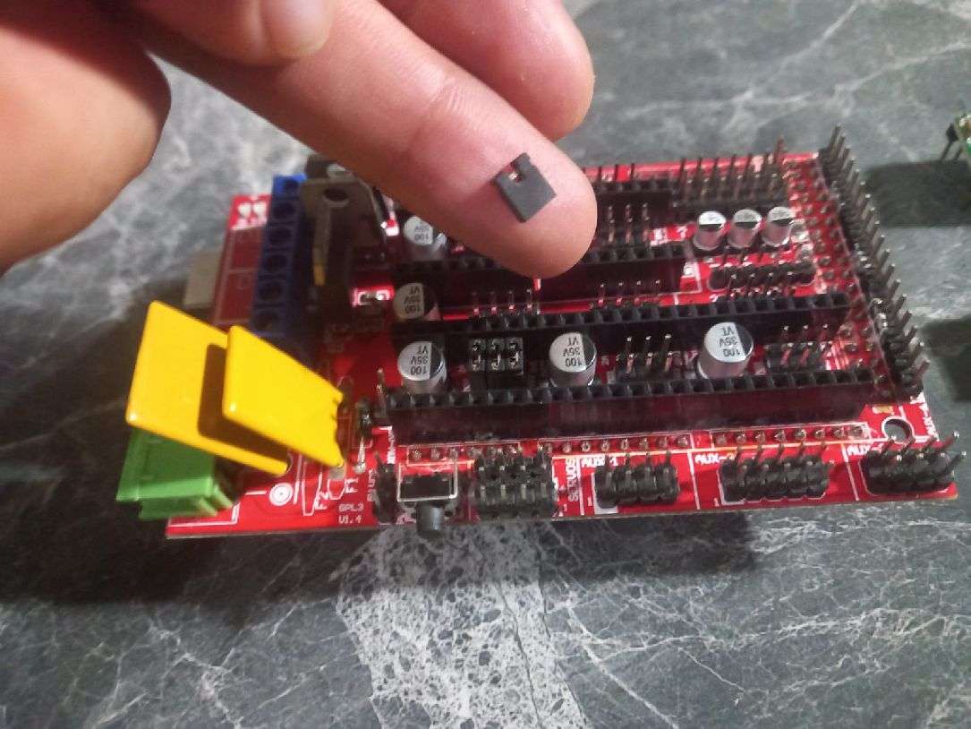
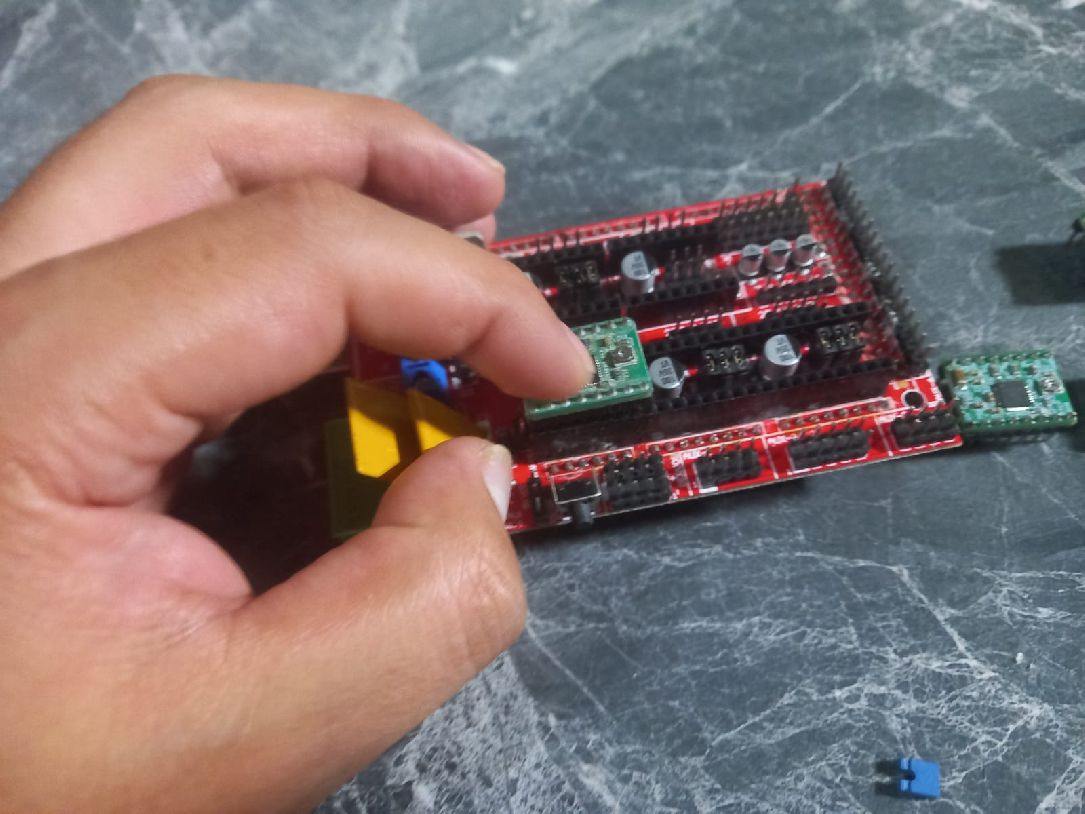
We place all the components, such as the jumpers, as shown in the image, with three of them on each motor driver. This configuration is done to improve the resolution of the engine.
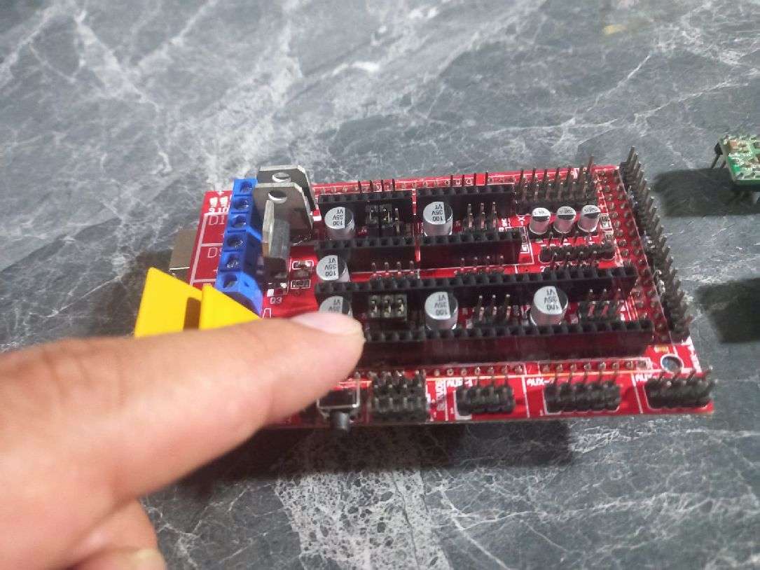
The image provides the guide to correctly place the limit switches of the 3 axes.
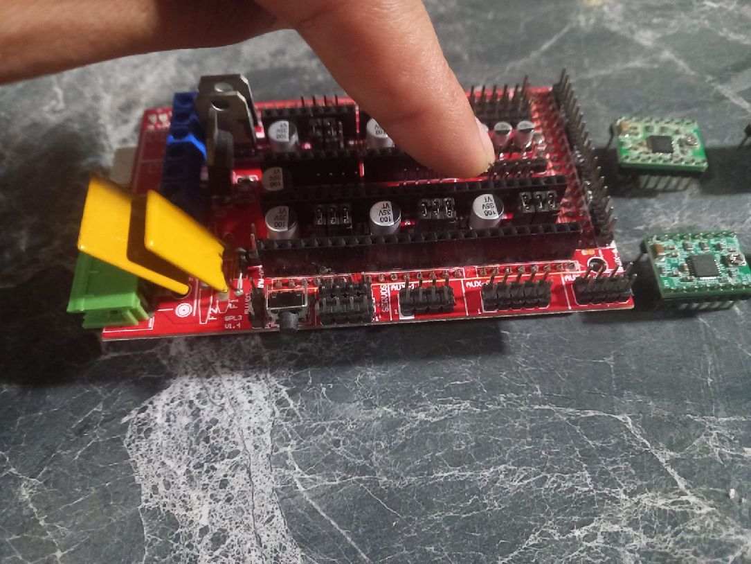
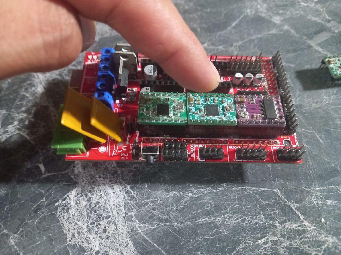
The following image shows the correct placement of the Pololu A4988 drivers. It is crucial to follow this guide in detail, since the wrong direction can irreparably damage the drivers.
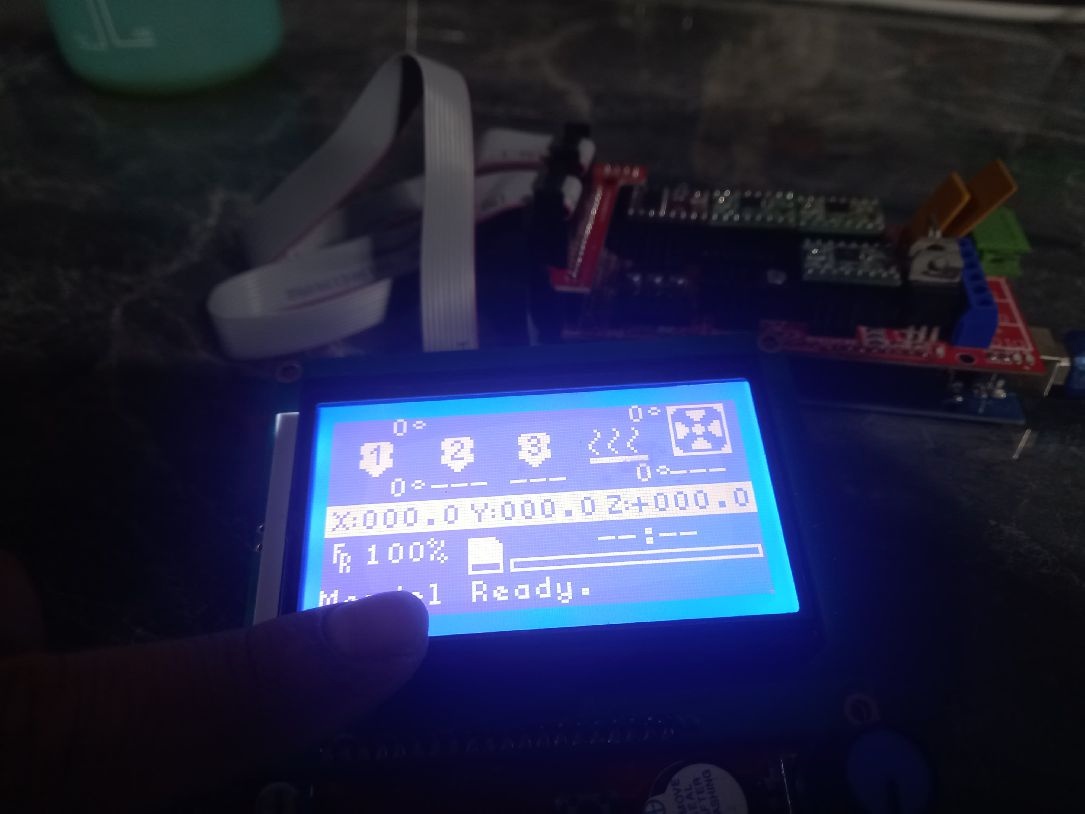
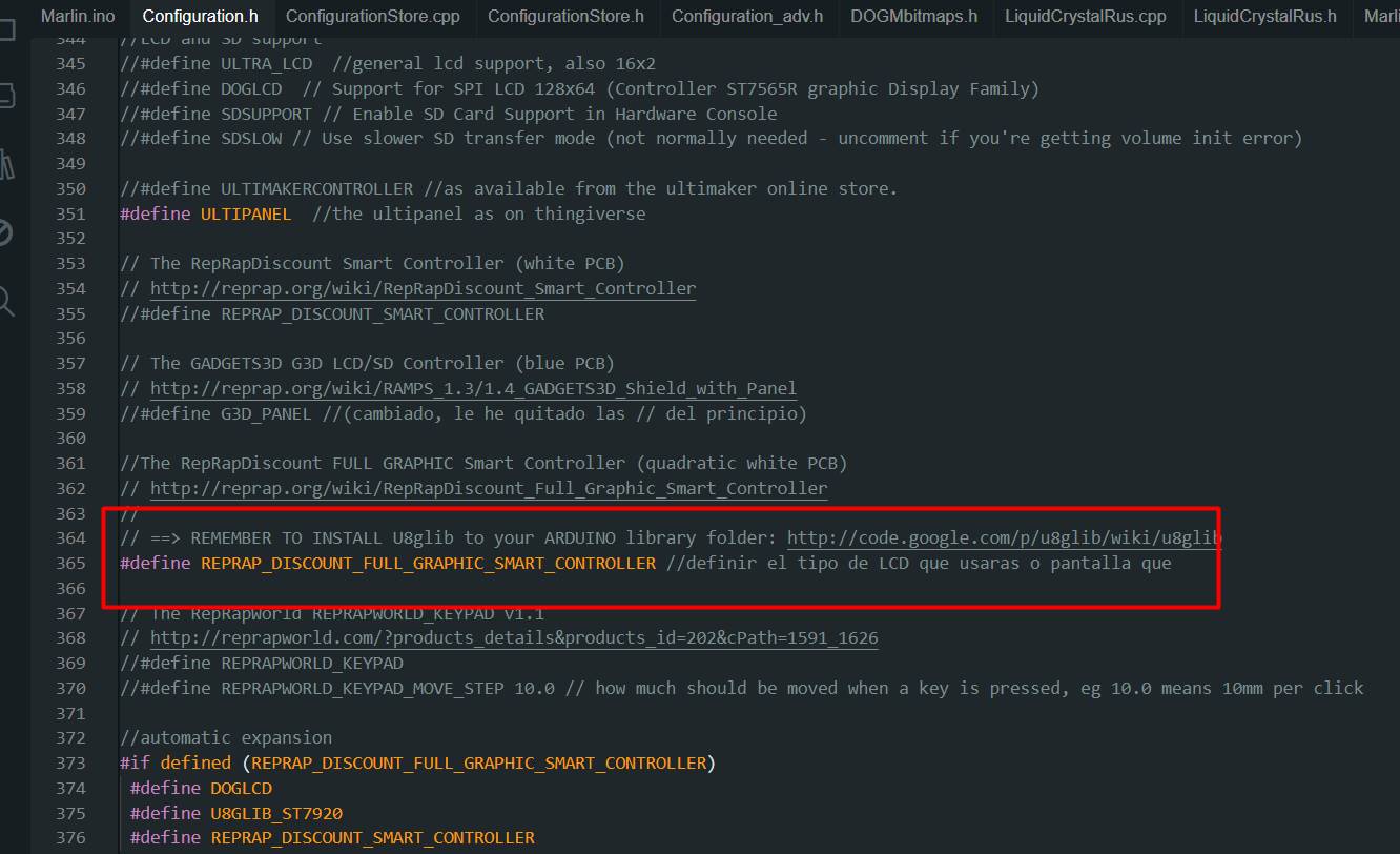
The following image illustrates the correct placement of the graphic LCD. It is extremely important to follow these settings to ensure proper operation.
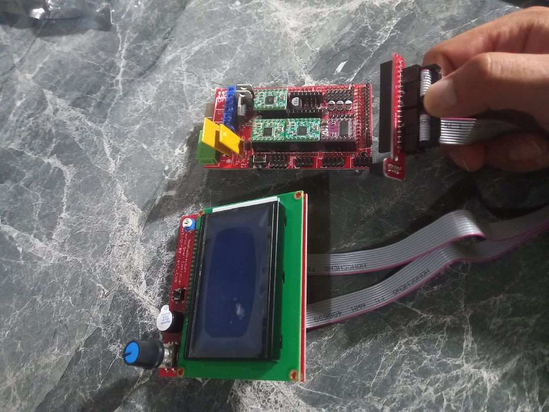
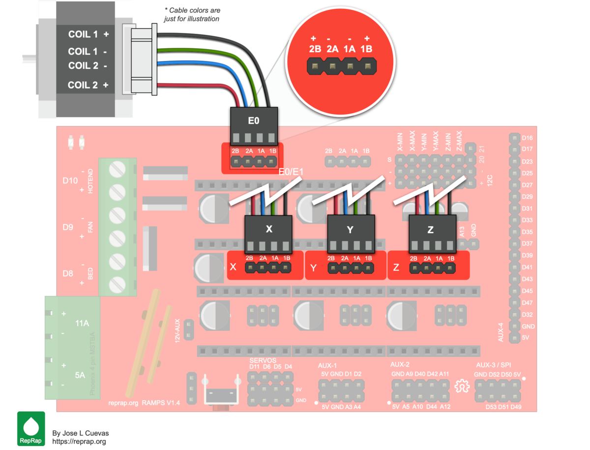
The following image confirms that our LCD is operational and presents the correct way to position the extruder motor. It is essential to follow these instructions for optimal system operation.
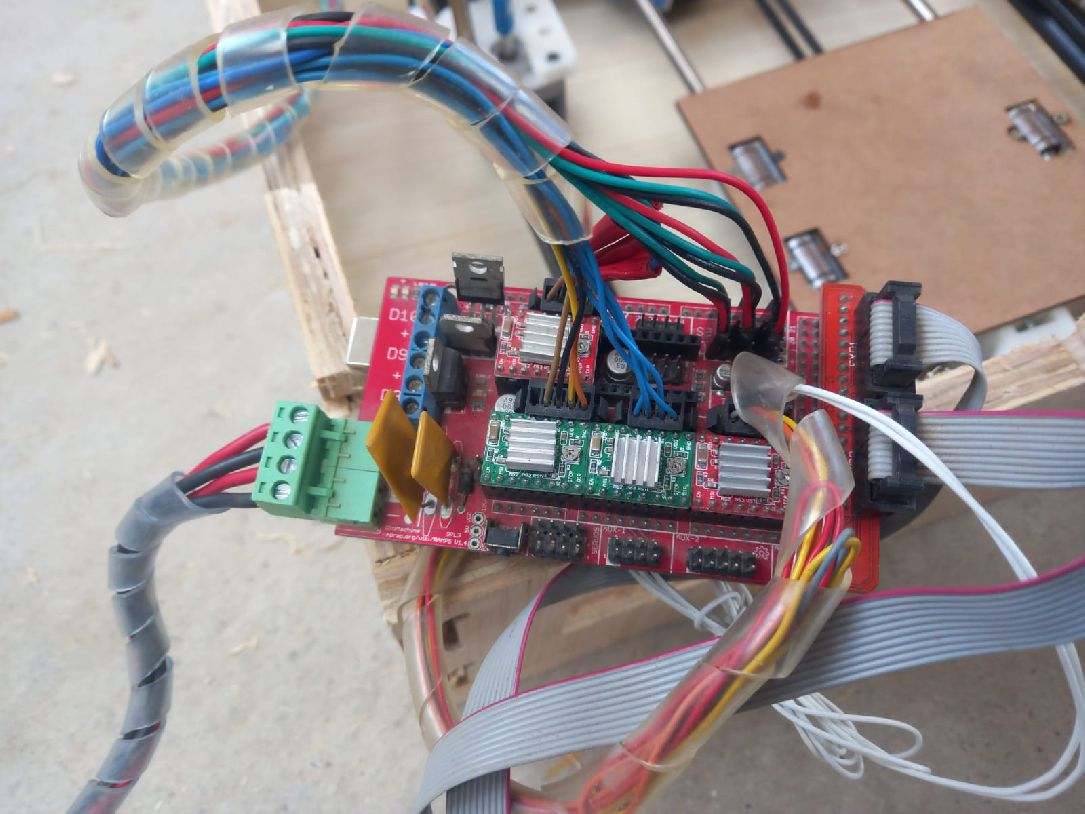
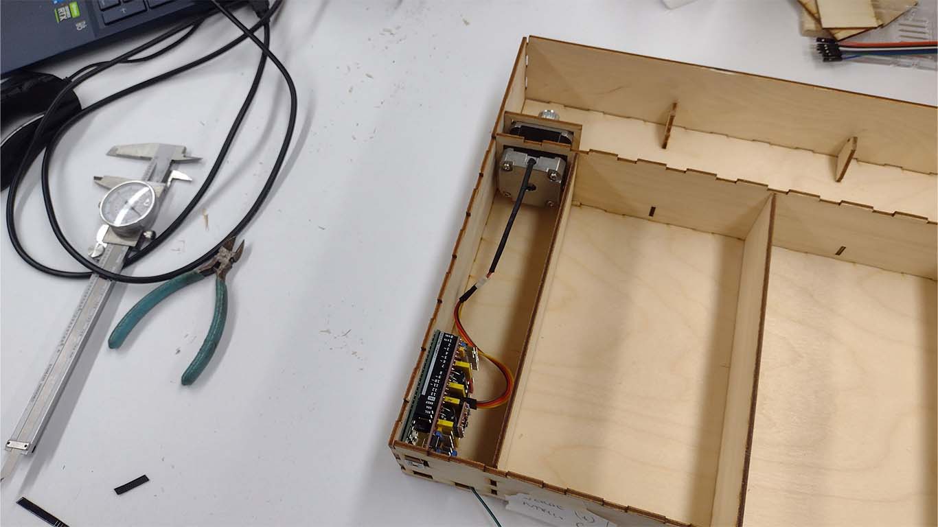
The next step is to place the electronics inside the box specially designed for the machine, firmly securing all the connectors.
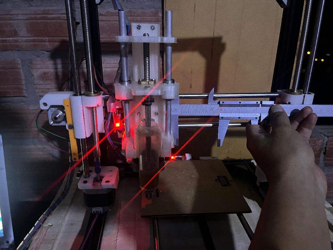
Machine calibration stage
Calibration is a critical stage of machine setup as it determines whether it will work correctly or not. It is crucial to devote time and attention to this process to ensure optimal performance.
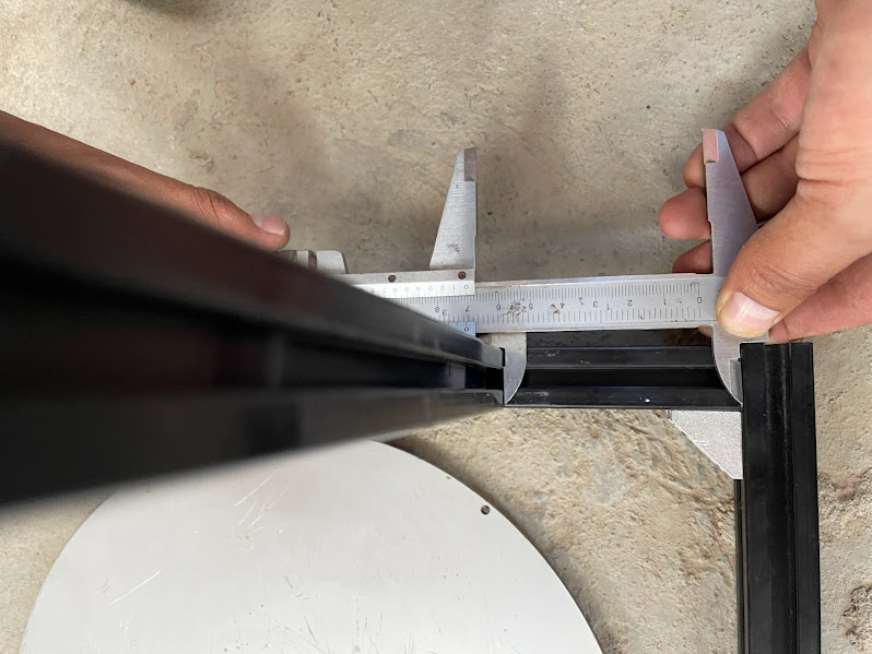
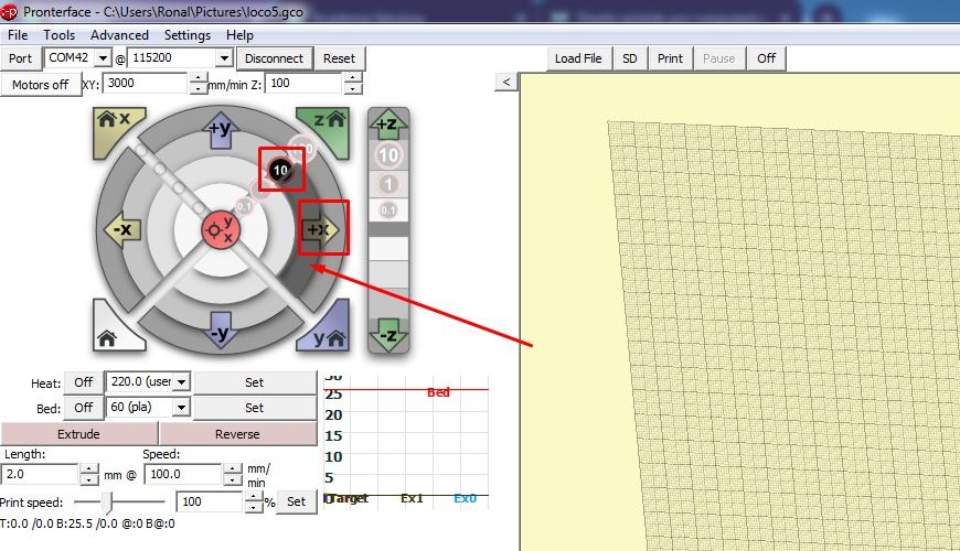
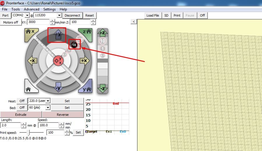
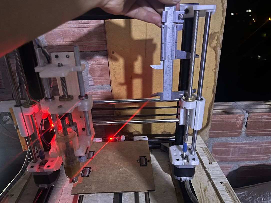
The following image shows the process of measuring the displacement on the X axis using the Bernier tool. The procedure is as follows: we place the Bernier on the X axis and then, in the Pronterface software, we indicate a displacement of 10 mm. The machine will move and we will take this measurement to perform the corresponding steps per millimeter calculations in the software.
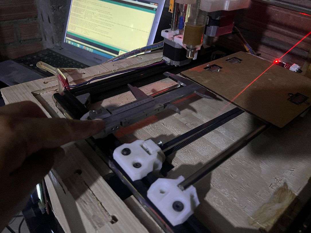
Similarly, the next step involves measuring the displacement on the Y axis using the Bernier tool. We place the Bernier on the Y axis and, through the Pronterface software, we indicate a displacement of 10 mm. The machine will move and we will record this measurement to carry out the necessary steps per millimeter calculations in the software.
If you got a value of 100.63 steps per millimeter when measuring the displacement with the Bernier tool, and you are using 21-tooth GT2 pulleys and a GT2 belt, then this value is effective for your setup.
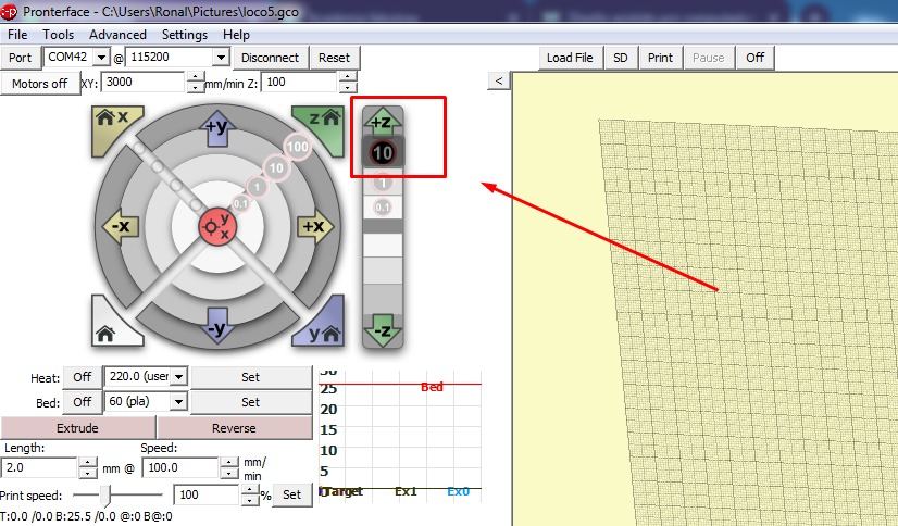
The following image shows the process of measuring the displacement in the Z axis using the Bernier tool. The procedure is similar to that of the X and Y axes: we place the Bernier on the Z axis and, using the Pronterface software, we indicate a displacement of 10 mm. The machine will move and we will record this measurement to perform the respective calculations of steps per millimeter, taking into account that we are using an M8 Spindle and two NEMA 17 0.7 amp motors.
Programming
The line
#define DEFAULT_AXIS_STEPS_PER_UNIT {100.63,100.63,404.7,150}
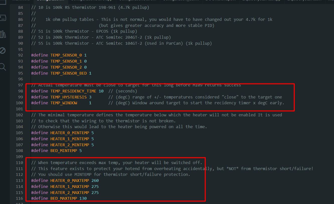
- HEATER_0_MAXTEMP: This parameter sets the maximum temperature allowed for the main hotend (extruder), which generally corresponds to the printer's primary extruder. In this case, it has been set to 260 degrees Celsius. If the hotend temperature exceeds this limit during printing, the heater will automatically turn off to prevent overheating.
- HEATER_1_MAXTEMP and HEATER_2_MAXTEMP: These parameters set the maximum temperature limits for the additional hotends, if the printer has more than one extruder. In this case, both have been set to 275 degrees Celsius.
- BED_MAXTEMP: This parameter sets the maximum temperature limit for the heated bed of the 3D printer. It has been set to 130 degrees Celsius. As with hotends, if the heated bed temperature exceeds this limit, the heater will automatically shut off to prevent overheating.
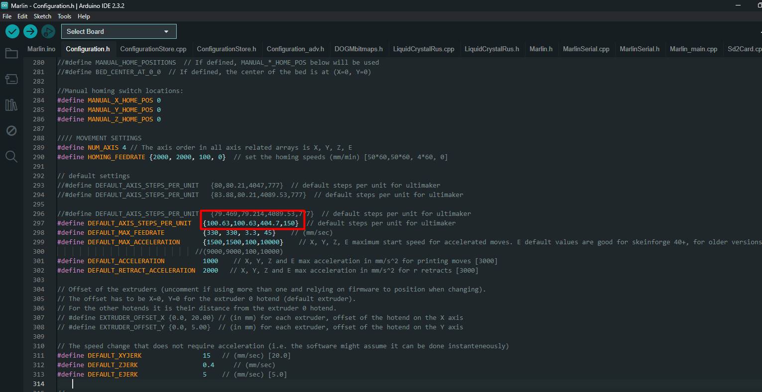
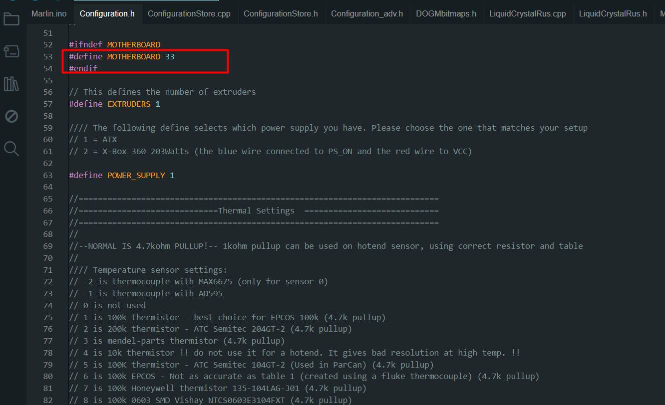
The program we use is called Marlin. It is an open source firmware designed primarily for 3D printers, but we realized that it could adapt perfectly to our food machine. With Marlin, we were able to precisely control every movement of our machine
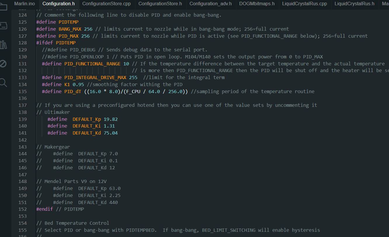
- PID_INTEGRAL_DRIVE_MAX: This parameter sets the maximum limit for the integral component of the PID control. The integral component is responsible for correcting the error accumulated over time. In this case, it has been set to 255, which is the maximum value for an unsigned byte.
- K1: This parameter is a smoothing factor used within PID control. Helps smooth out changes in controller output. In this case, it has been set to 0.95.
- PID_dT: This parameter specifies the sampling period of the PID control. It is the amount of time between each temperature reading used by the PID controller. In this case, it is calculated using the CPU frequency and other factors.
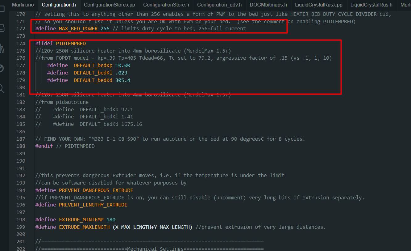
Although on this occasion we do not plan to use the heated bed in our machine, it is important to highlight its connection and presence. The heated bed is not only essential for printing certain materials, but also plays a crucial role in the stability and accuracy of the overall print. Maintaining the option to use the heated bed gives us flexibility and the ability to work with a wider variety of materials in the future. Additionally, having the heated bed connected and ready for use prepares us for any future printing needs that may arise, thus ensuring that our machine is fully equipped and ready for any project we tackle.
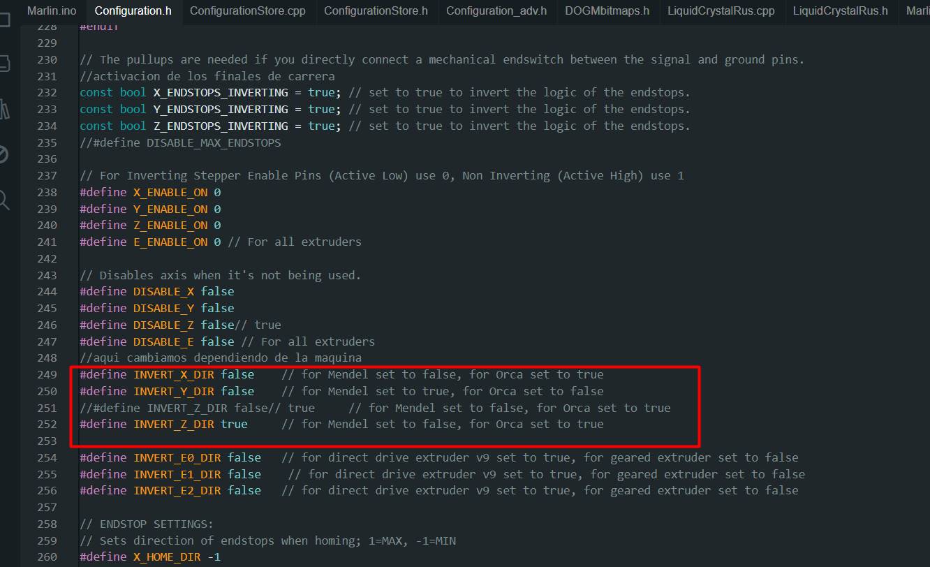
- INVERT_X_DIR: This parameter controls whether the motor direction for the X axis should be inverted or not. In this case, it has been set to false, which means that the motor direction for the X axis will not be reversed. For a Mendel type printer, this is usually correct.
- INVERT_Y_DIR: Similar to the previous one, this parameter controls the motor direction for the Y axis. Here it has also been set to false, which means that the motor direction for the Y axis will not be inverted. For a Mendel type printer, this is usually correct.
- INVERT_Z_DIR: This parameter controls the direction of the motor for the Z axis. It has been set to true, which means that the direction of the motor for the Z axis will be inverted. This is commonly necessary for an Orca type printer.
- INVERT_E0_DIR, INVERT_E1_DIR, INVERT_E2_DIR: These parameters control the motor direction for the extruders (E0, E1, E2 respectively). In this case, they have all been set to false, meaning that the motor direction for the extruders will not be reversed. This may vary depending on the type of extruder used in your printer (direct or geared).
- One of the most significant challenges we faced when building the superfood machine was the difficulty in finding an effective system that could push the material through the extruder. To address this situation, our team came up with an ingenious solution: we used 60 ml syringes that we found available at a livestock supply store. This adaptation allowed us to overcome the obstacle and continue the process of building the machine successfully.
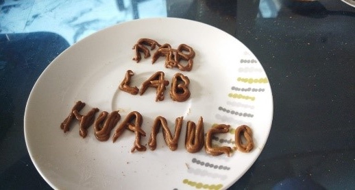
- Achieving the desired consistency in superfoods was a challenge for our team. During the process of making layer after layer, we discovered that the combination of maca and banana flour responded well to our formula, in contrast to tocosh, coca flour, where we did not obtain the expected results. Faced with this situation, we have decided to go back to the drawing board and develop a new formula that allows us to process these superfoods more effectively.
- We are facing significant difficulties with the structure of our machine, especially due to the shortage of components available in our city. However, thanks to Garage Lab's generous donation, we were able to address this problem in an innovative way. We recycled an Anycubic Kossel Delta DIY 3D Printer to obtain the necessary parts, which allowed us to overcome structure-related obstacles and successfully move forward in building our machine. This creative solution showed us the importance of collaboration and ingenuity in solving technical problems.
- One of the challenges we faced was material shortages during the holidays, which resulted in significant delays in building our machine. The lack of availability of necessary components forced us to wait longer than expected to complete the project. This situation highlights the importance of careful planning and anticipation of potential setbacks during the construction process.
- Our tutors play a crucial role in providing us with support and guidance throughout the machine building process. We were advised to start as soon as possible, given the labor-intensive nature of the project. Despite our desire to get started immediately, the holidays prevented us from moving forward as planned. However, their continued guidance and encouragement was instrumental in keeping us focused and motivated as we overcame obstacles and moved forward with our project.
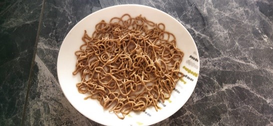
- One of the difficulties we faced was finding the right formula to extrude the maca effectively. After experimenting with the combination of chuño, maca and water, we noticed that the resulting density did not meet our requirements. We decided to investigate and test using only maca and water, which gave us much more satisfactory results in terms of consistency. Therefore, we opted to stick with the formula that only included maca and water, which allowed us to successfully achieve the desired goal of extrusion.
- To improve our product we have the reformulation of maca, coca and tocosh. With a new combination of elements we can improve our composition.
- In the structure we have difficulty getting the flexible coupling. Then it is solved with a hose. To be able to place the coupling, for the next versions we can use the metal coupling.
- In our version number 1 the board we are using is an arduino mega with a 3D Printer Controller Board RAMPS 1.4 Arduino Mega Shield
- For a possible improvement in this project we could add a little honey to the maca consumable to make it sweeter, since maca can be a little sour.
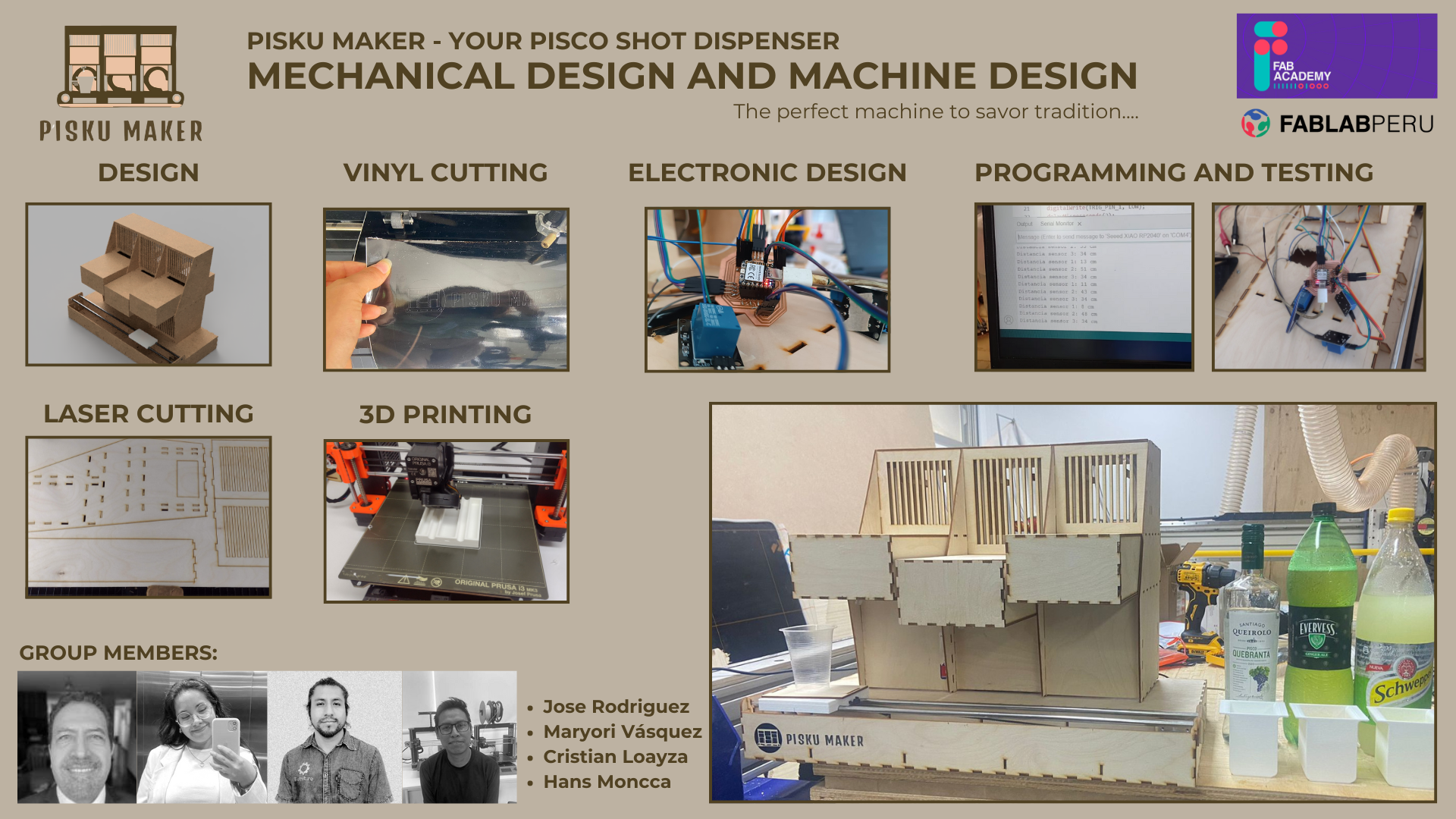
Group 2: PISKU MAKER
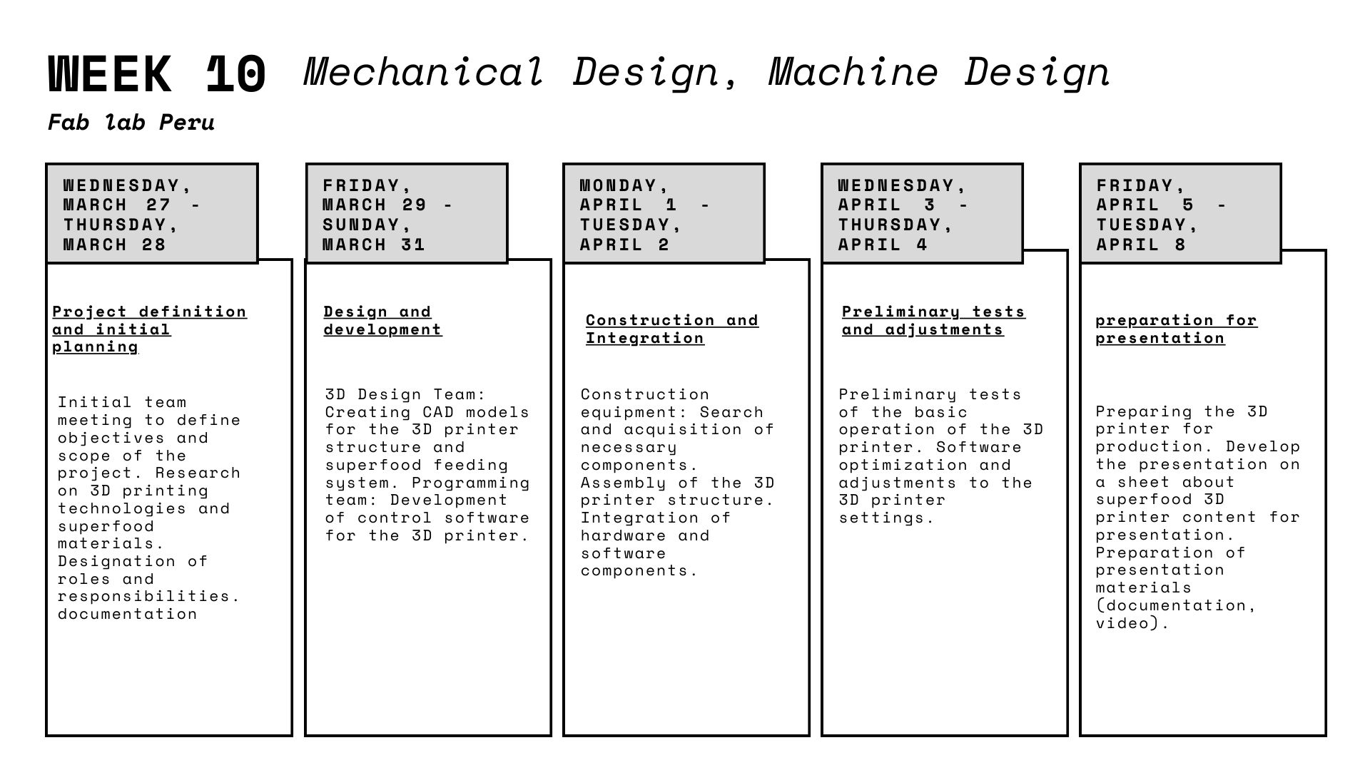
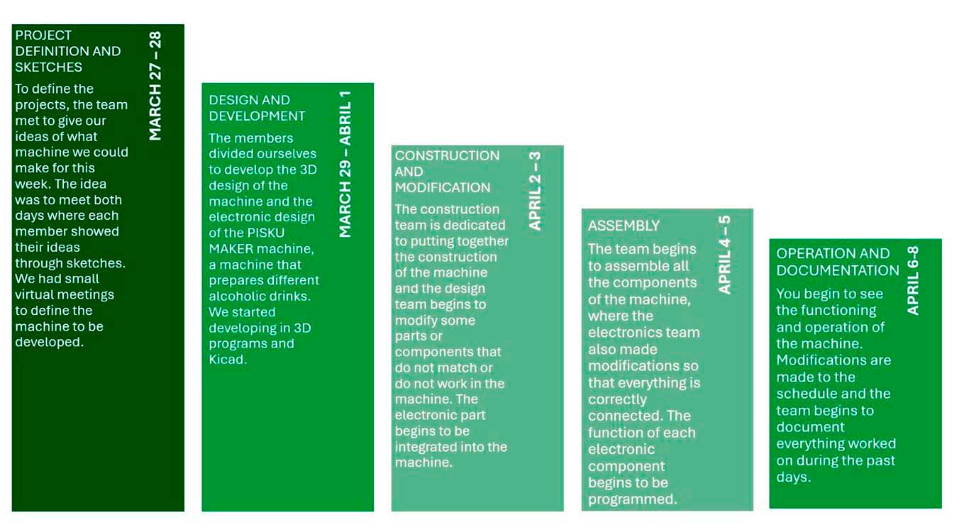
PROJECT DEFINITION
To develop the assignment, we had to meet and define our plan to be able to meet the objective of fulfilling the assignment. Therefore, we organized ourselves and scheduled dates where we had to complete certain tasks the days before the presentation of the machine. Here is a photo of our organization for the assignment.
PROJECT AND SKETCHES
After meeting virtually to discuss the machines that each one proposed to make. We chose the best option, which was the PISKU MAKER, a machine that prepares different types of drinks and mainly pisco sour, originally from Peru. From this, you proposed sketches of what the shape could be and we chose something more compact because we proposed to work with a machine that can be developed without screws and rubber bands. So, we wanted to achieve a machine that is assembled through joints, all according to what we have learned at the FAB ACADEMY so far. Here is a screenshot of a sketch made by my colleague Maryori of how we defined it.

DESIGN
After having an idea of what the machine would be like, we took care of working on the design in both 2D and 3D, where we began to model the entire structure of the machine so that everything can work through joints or press fit. The objective was to achieve this to avoid using glue or screws as are common in the machine. Here are some screenshots of the work done on the design in Fusion and Autocad for disassembly and then sending it to be laser cut.
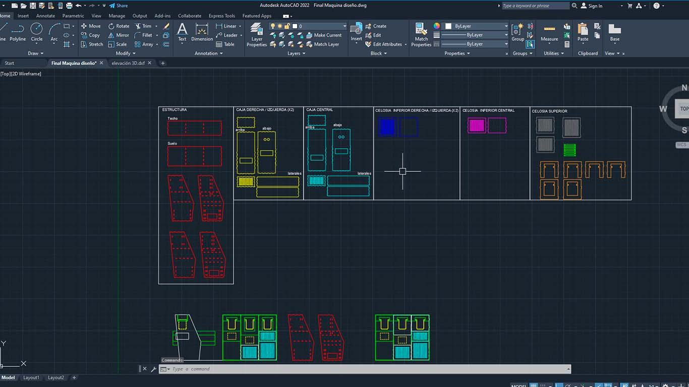

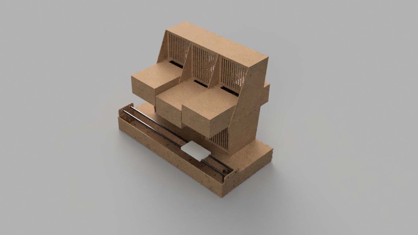
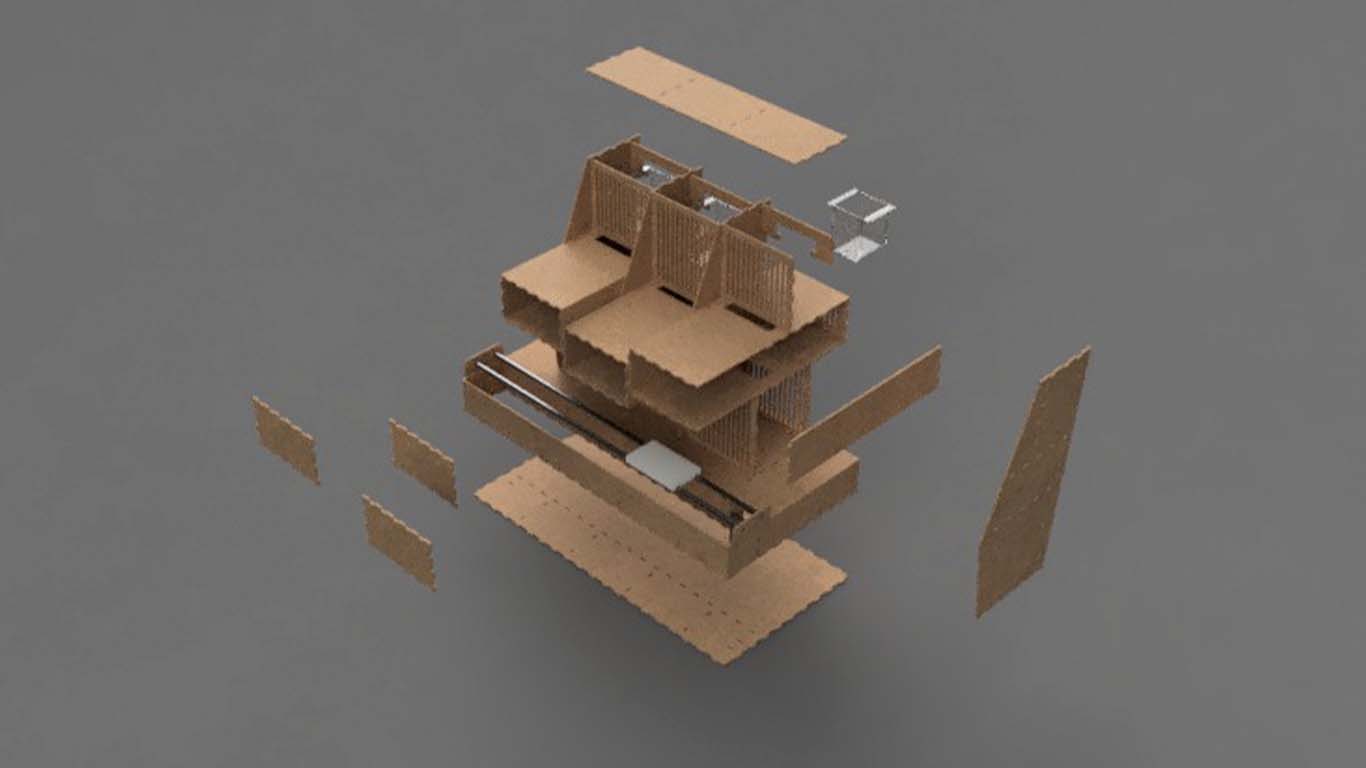
We made some renderings and also checked that all the joints can connect correctly. This is also how the part of the axis that will have movement was modeled so that a glass can move through the machine.
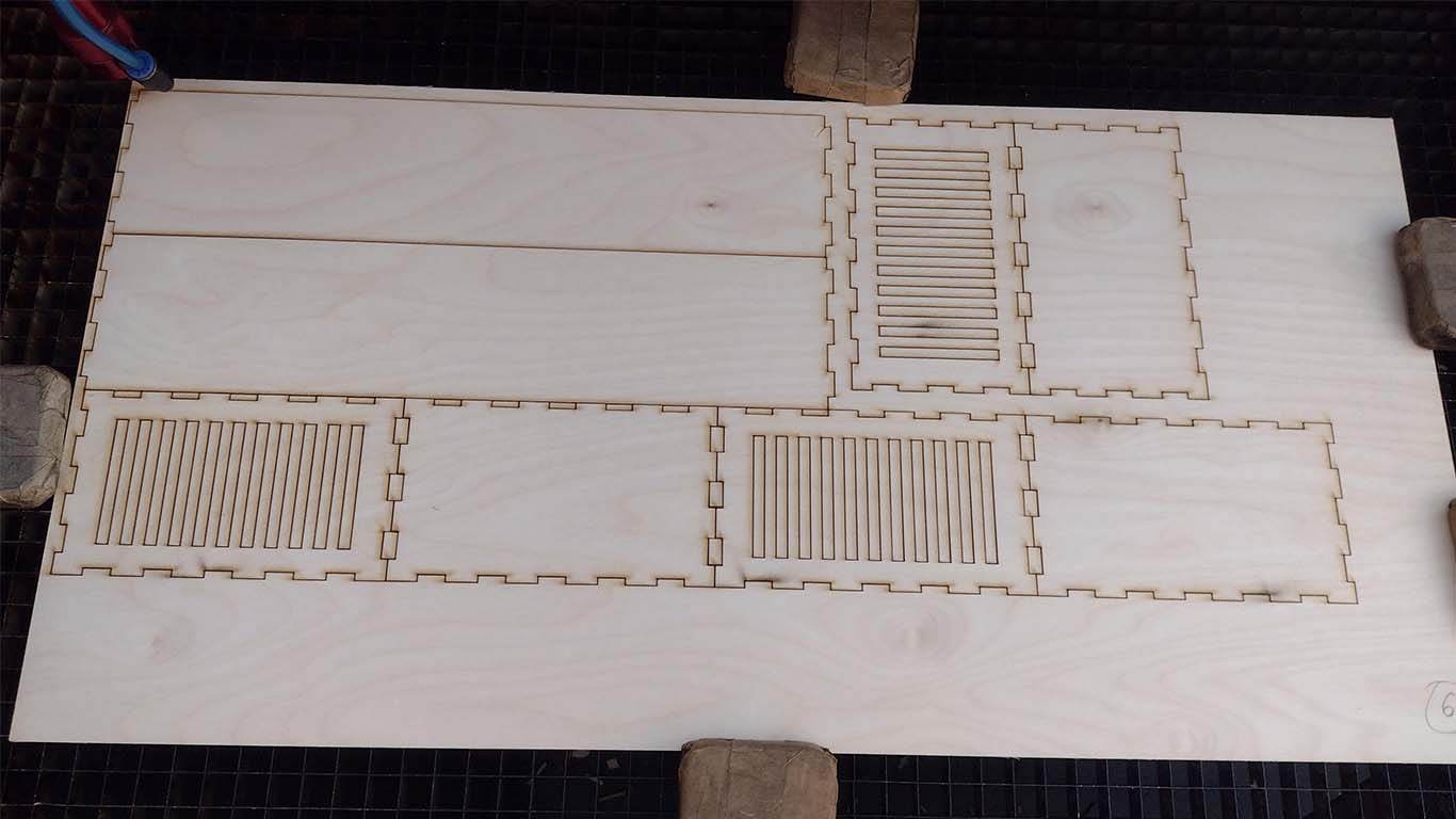
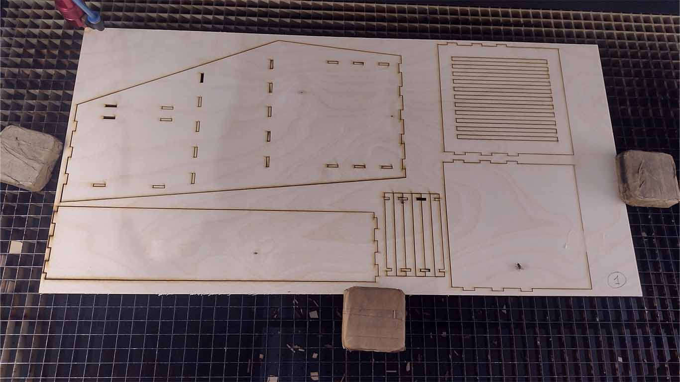
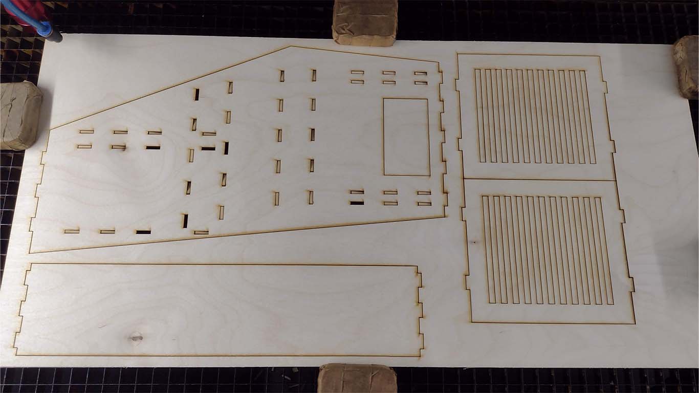
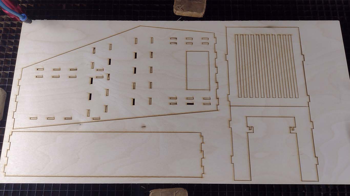
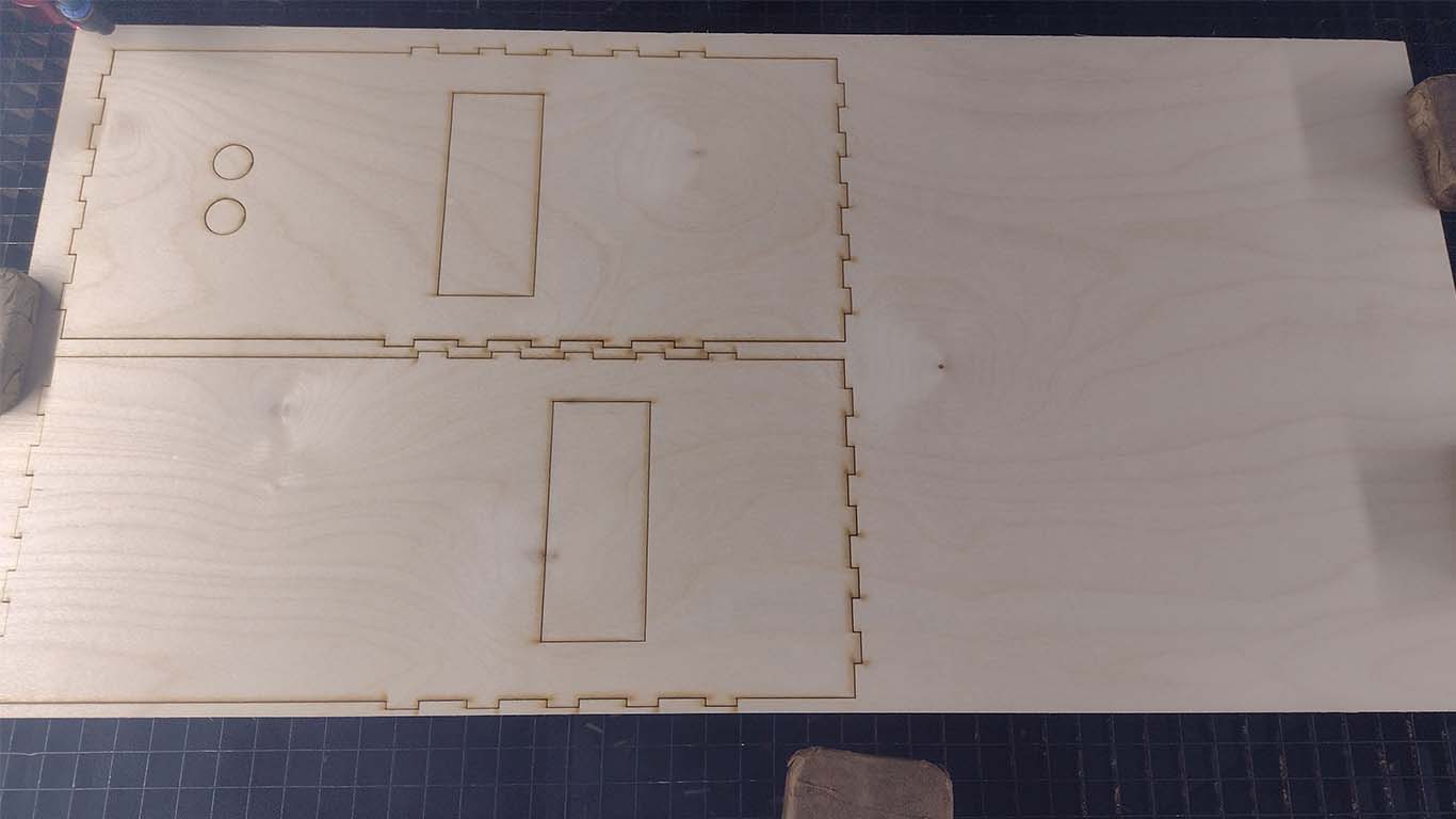
LASER CUTTING
After obtaining the design, we began to laser cut the entire structure of the machine in 3 mm PLYWOOD, it was a material that we already knew and that was tested in week 3 to find out its fitting characteristics. Approximately 9 sheets of 300 x 600 mm will be used, which is the standard size of the material. The cost is less than buying an MDF sheet here in Peru. Here are some cuts of the machine parts.
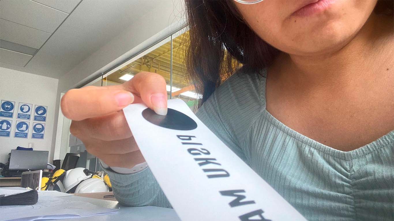
VINYL CUTTING
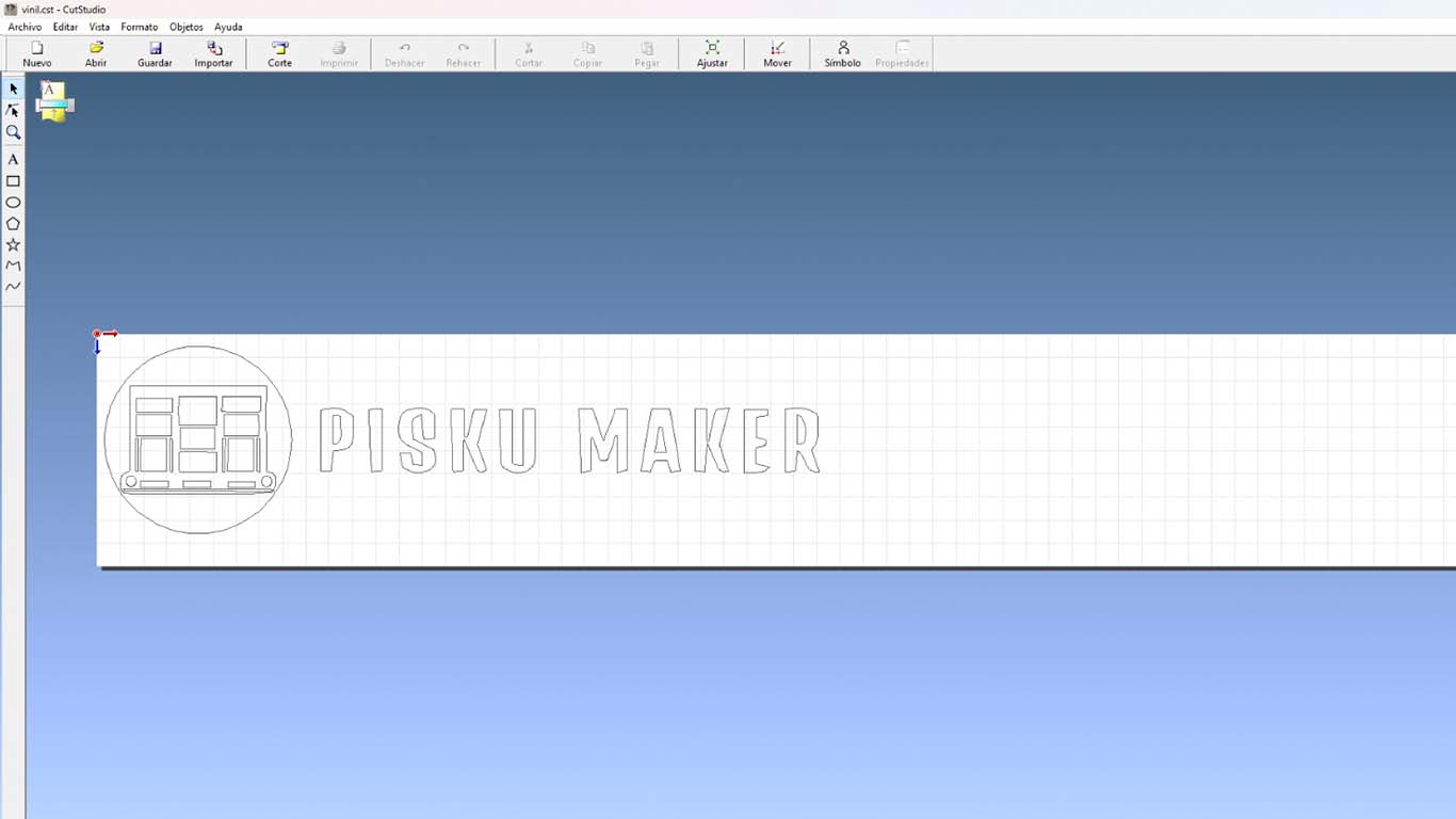
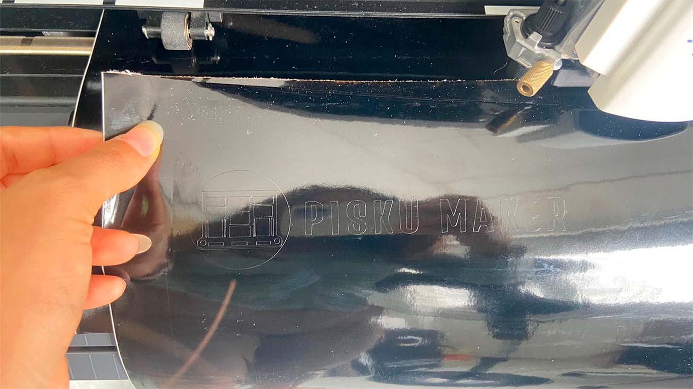
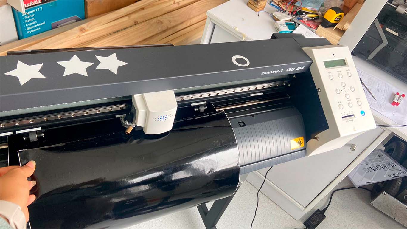
We wanted to give a characteristic to the machine, so Maryori dedicated herself to designing a logo that goes well with the design and characteristics of the machine. Here is the process of how we cut the logo in vinyl to paste it on the machine when we can have it. The logo was unique and characteristic of the machine.
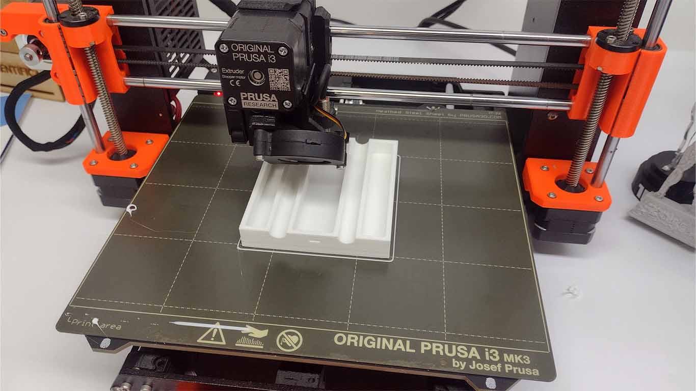
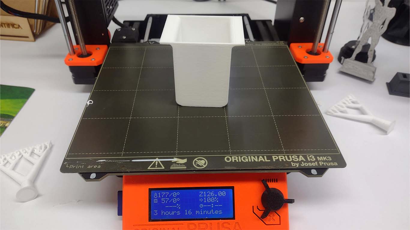
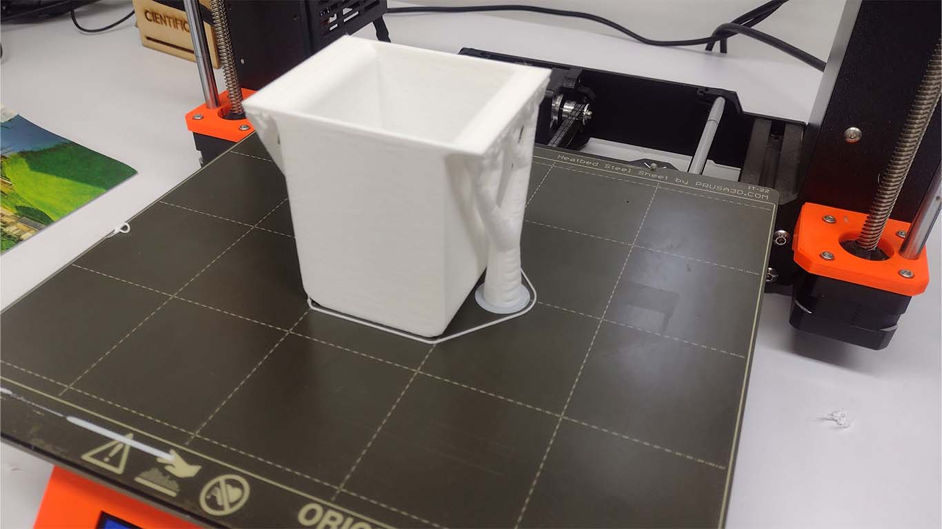
3D PRINTER
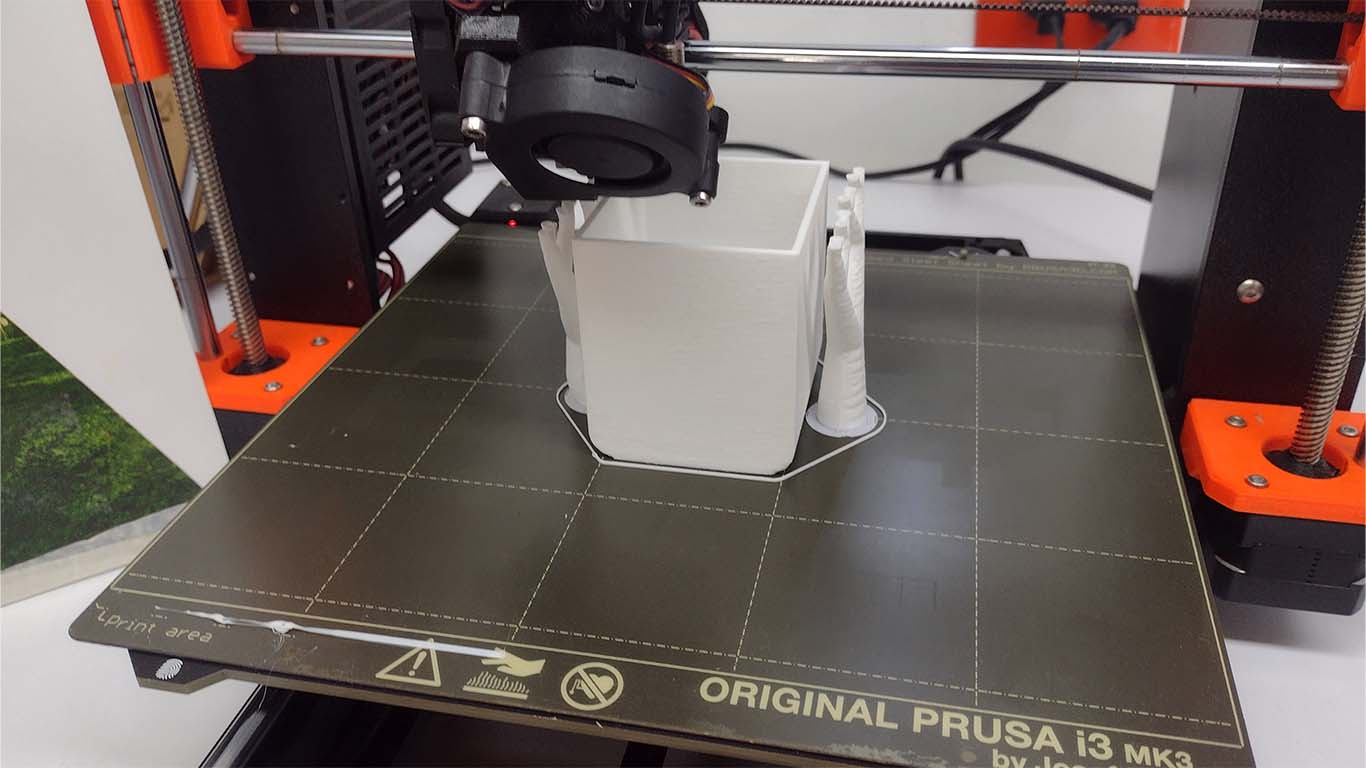
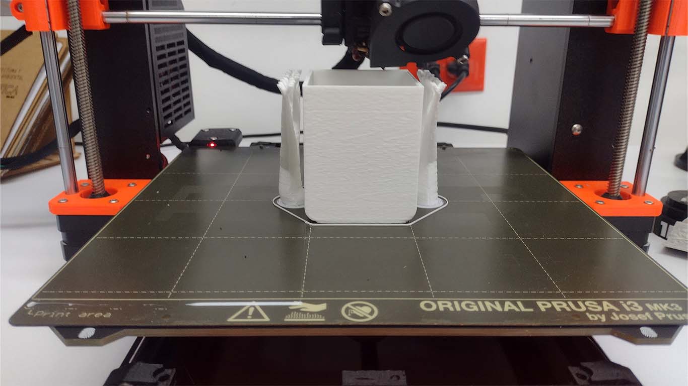
Likewise, for the machine we had to make 3D prints of the flag that will carry the glass where the drinks will be mixed and the containers where the drinks will go were also printed. Here are some photographs of the printing process, the containers took approximately 3:12 minutes to complete, all of these were printed with white PLA filament.
ELECTRONIC DESIGN AND TESTING
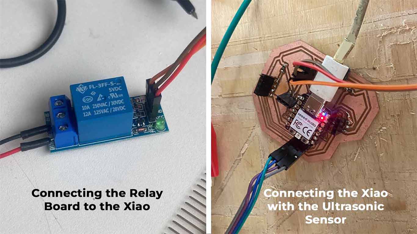
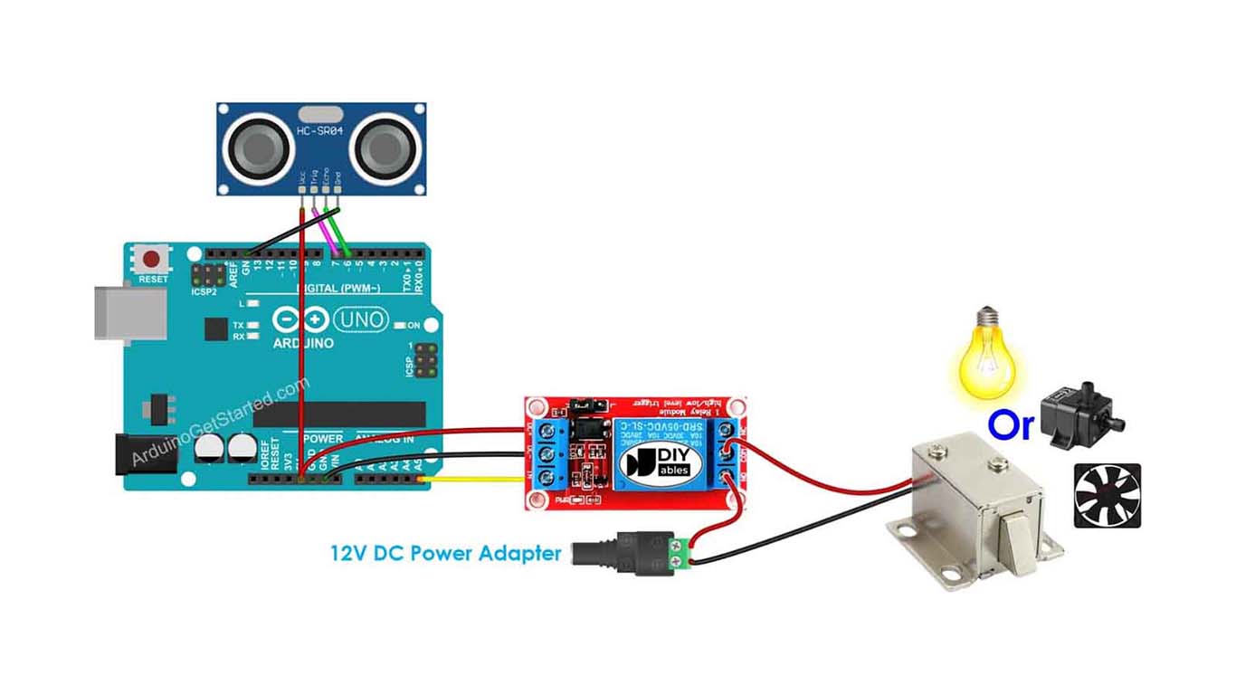
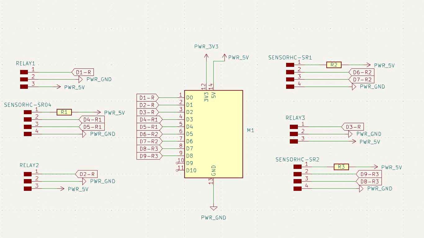
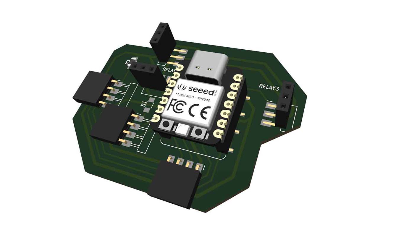
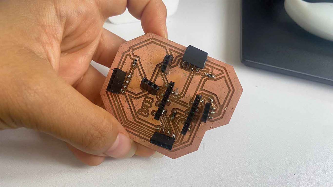
For the machine we had to design a board where we can include the XIAO RP 2040 to achieve its programming and operation. This board is aimed at controlling the dispenser of the machine. Where with pumps and ultrasounds, the idea is that when it comes to recognizing movement, the pumps can be activated and when we do not obtain measurements, they are turned off. Here I show the diagram and layout of the PCB.

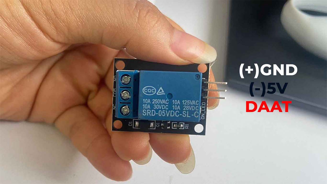
Before starting to design the board we had to research the electronic components that we will need to be able to place on the board and their connection method. Here are some components that we use to make the machine.
Then in the KICAD 8.0 program we began to design our board in diagram form and layout. Here are some screenshots of what was developed.
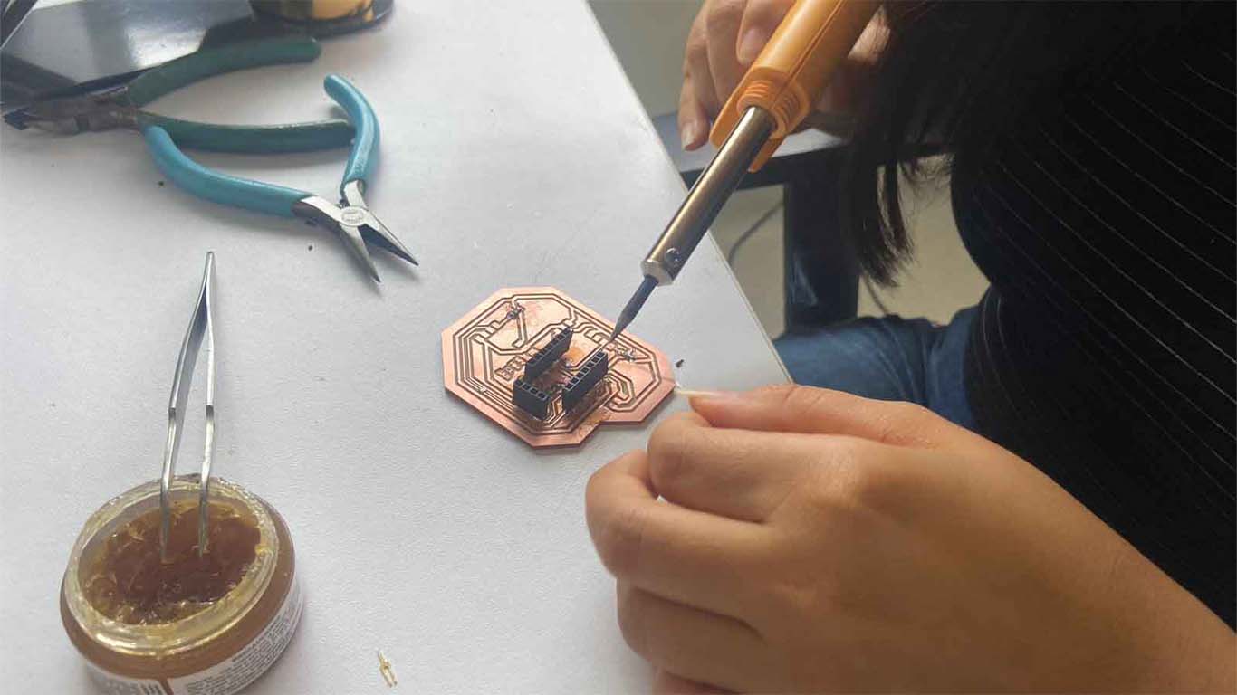
SOLDERING
Finally, after obtaining the design, we moved on to the stage of milling the board where we did it with MODS.CE and after obtaining the board, we moved on to milling the components that were going to go on the board.
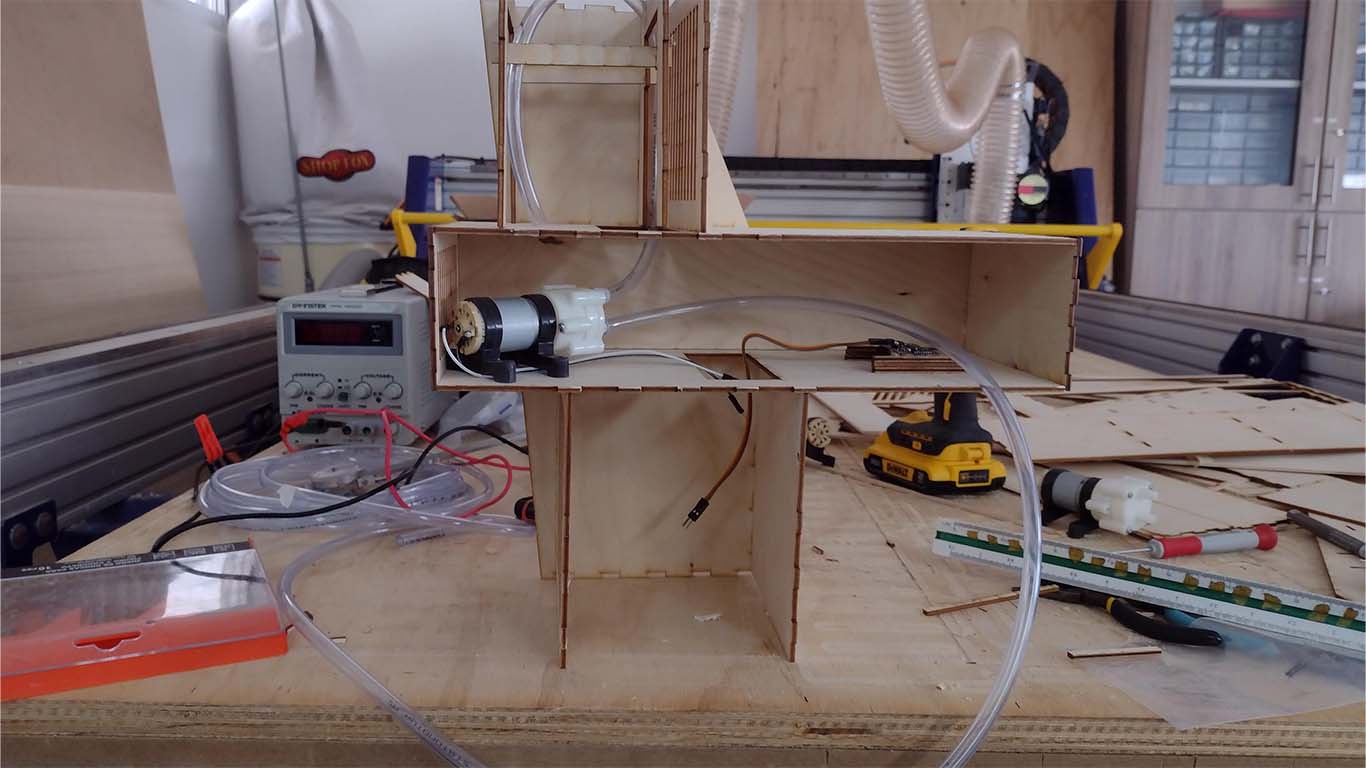
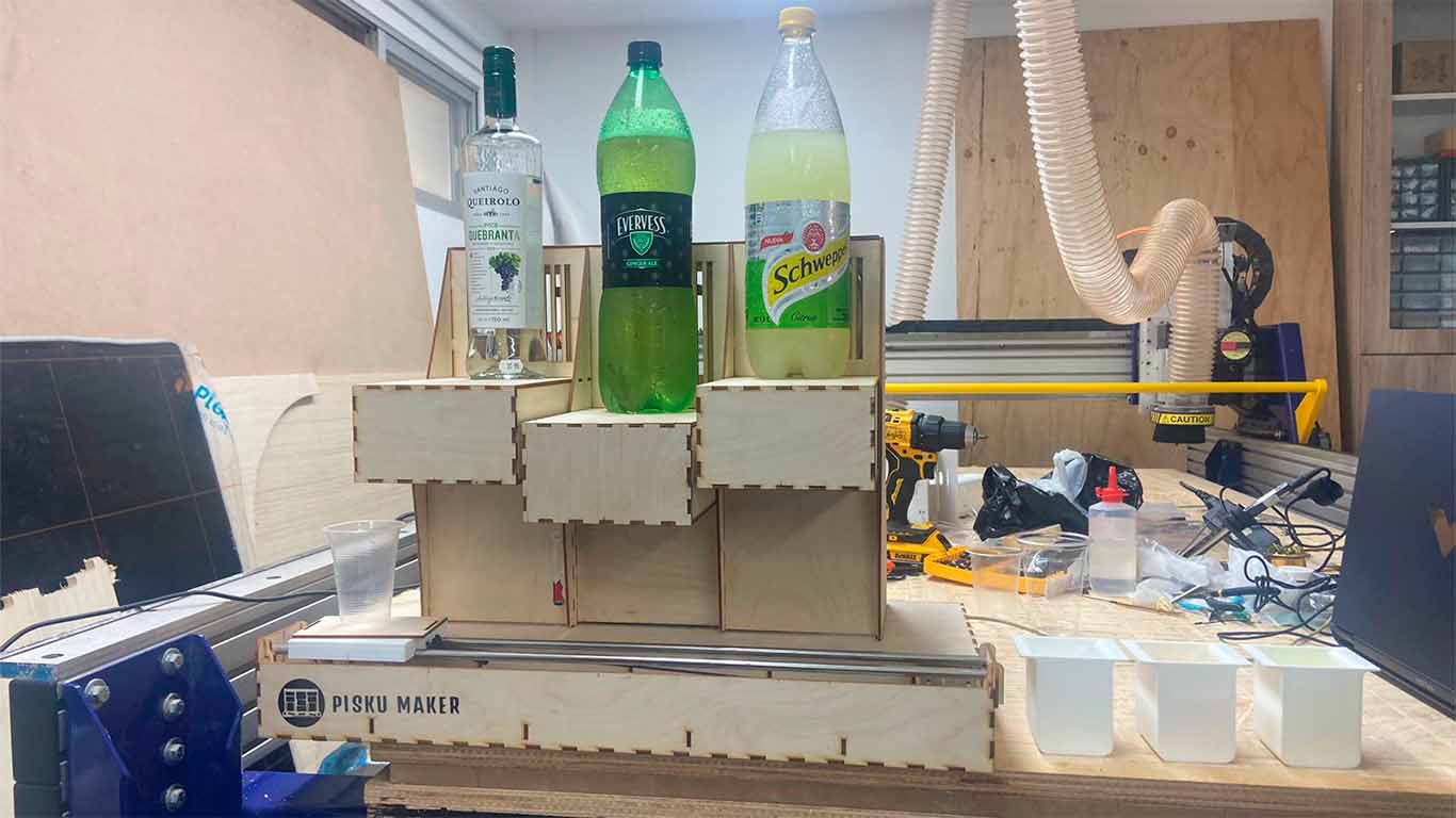
ASSEMBLY DISPENSER
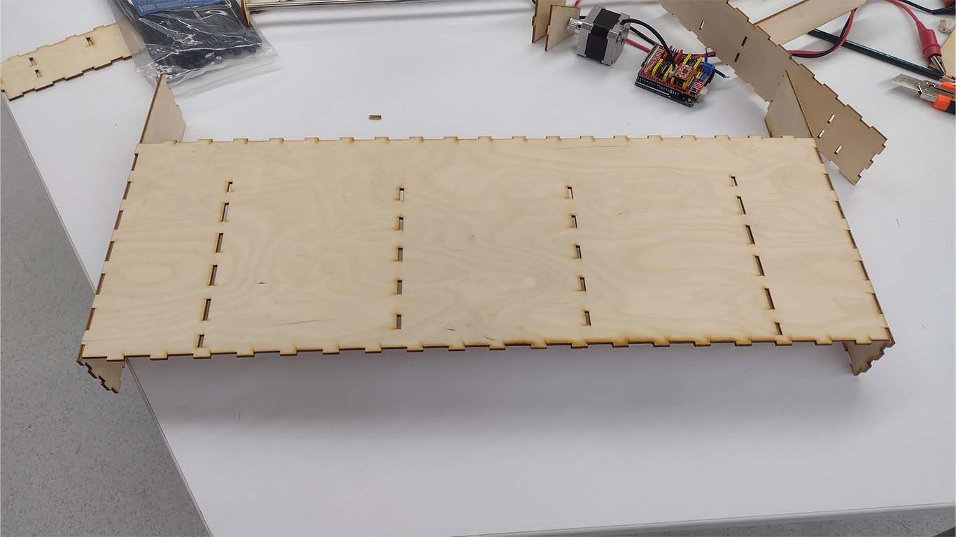
For assembly, we decided to start with the beverage dispenser since it seemed the most difficult to us, first we started by assembling the structure, everything should fit together with its parts and without using screws or glue. Finishing this, we begin to connect the motors, pipes and keys for programming and power in each of them. In the end it turned out very well, everything could be put together like a puzzle.
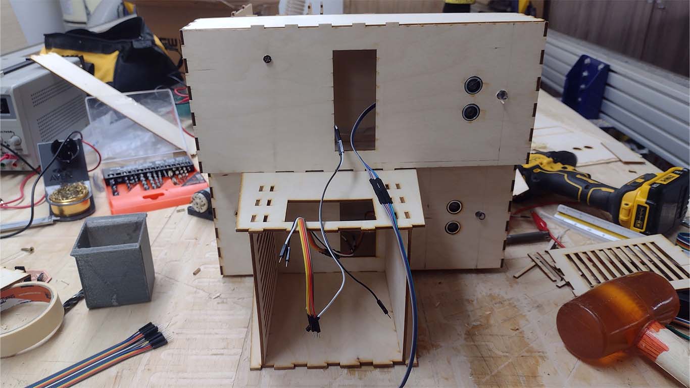
ASSEMBLY TRAY
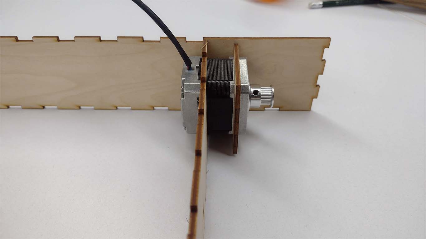
Like the assembly of the dispensers, the tray, where the glass will travel, was also done in the same way with press fit and we also added the electrical components such as the stepper motor and also an Arduino UNO with SHIELD to be able to program the stepper motor. Here are some screenshots of the process, remember that this base will receive the dispenser through press fit.
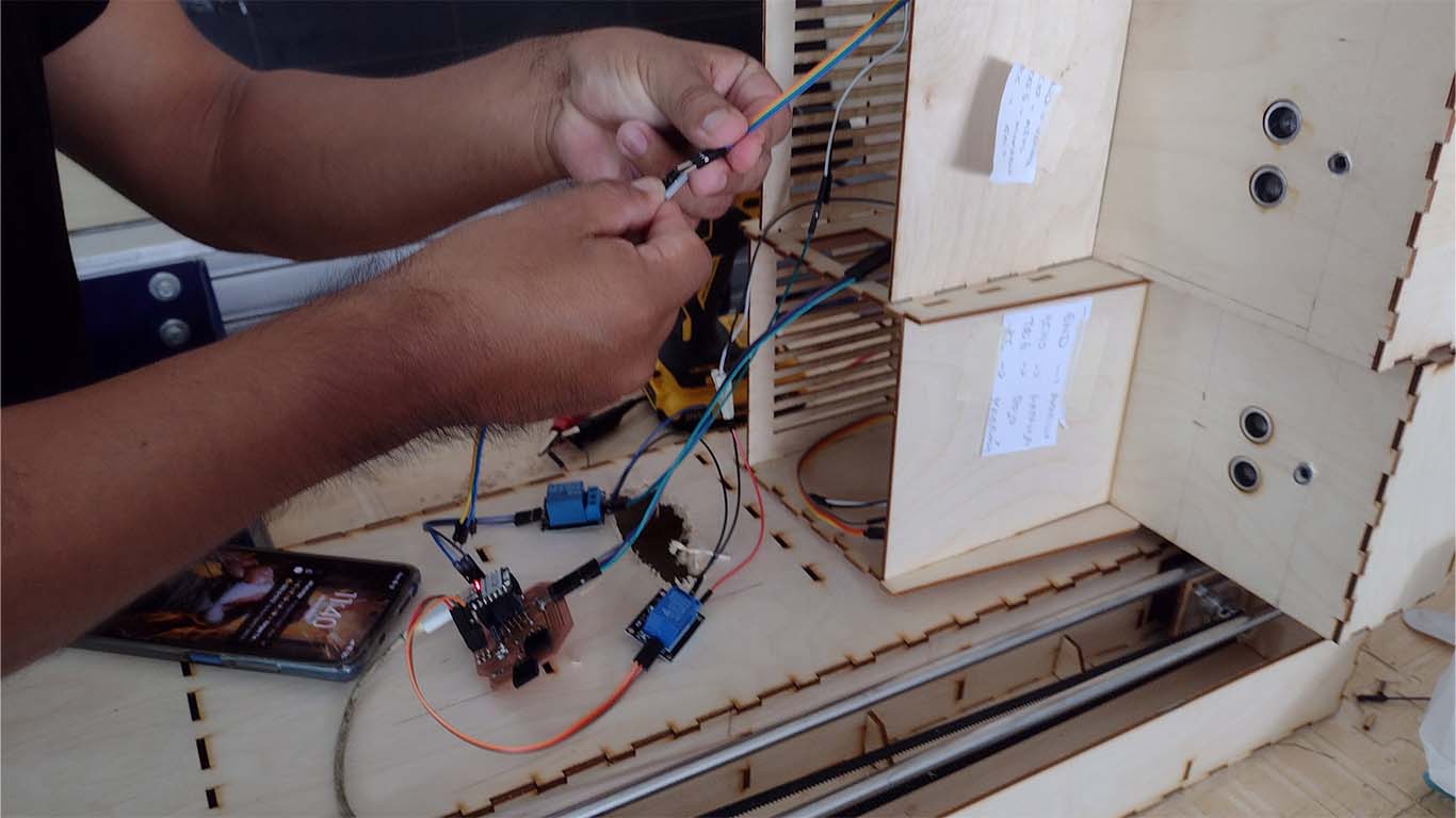
ELECTRONIC ASSEMBLY
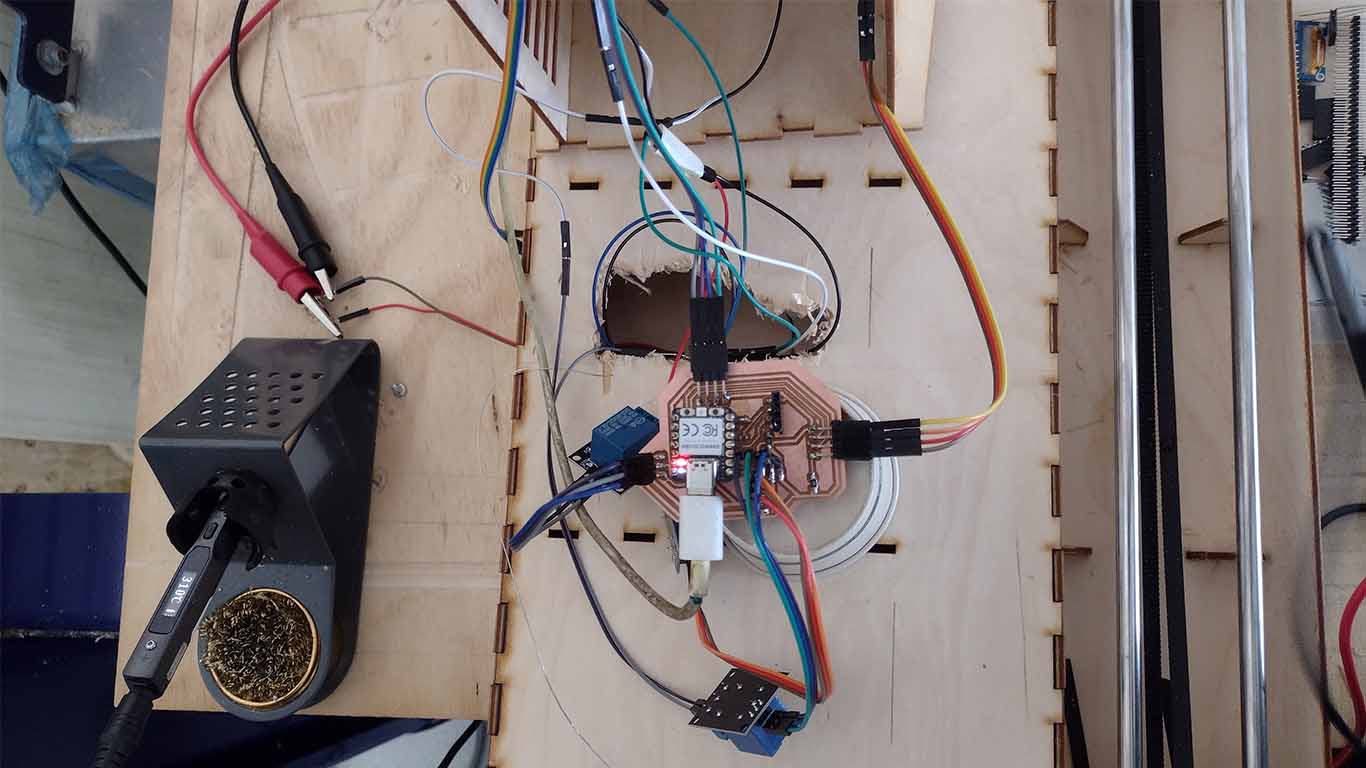
For the electronic assembly we had many complications because there were many cables and it confused us a lot when connecting each of them to the pins. In addition, we had to send the board to be milled twice since the first time some pins broke and it no longer worked. It was a low-stress stage but in the end we were able to put things in order and do a good job with them.


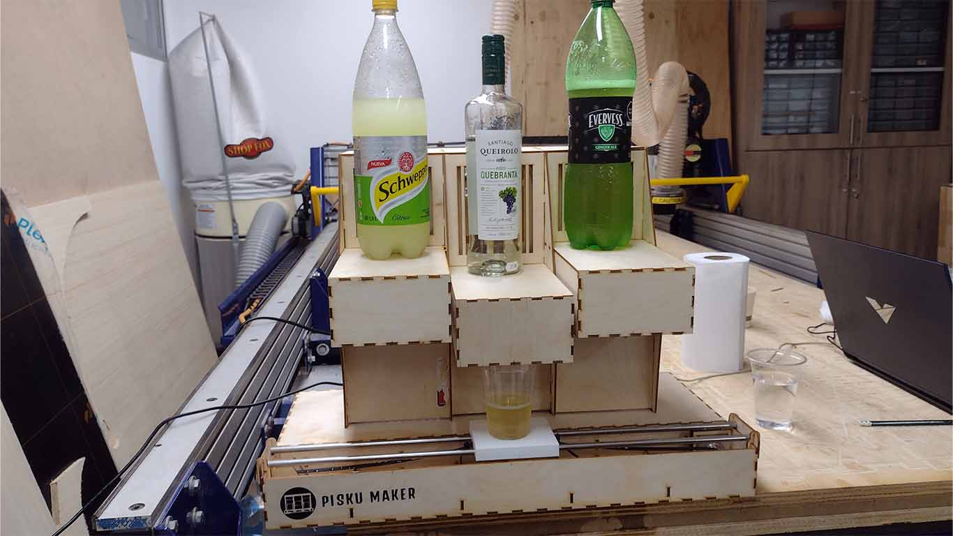
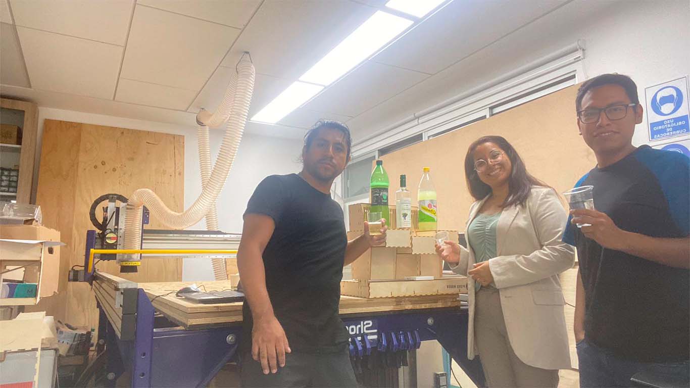
RESULTS
The results were very good in the assembly and design. But when it came to programming there were some things that we could not solve, mainly the communication between the motor and the ultrasound. It was complicated for us because we could not ensure that the ultrasound could only read when the glass passes and stop working when it is no longer there, because in operation, everything is fine, only the programming we needed to investigate more and synchronize properly for its correct operation.
Problems described and how the team resolved them
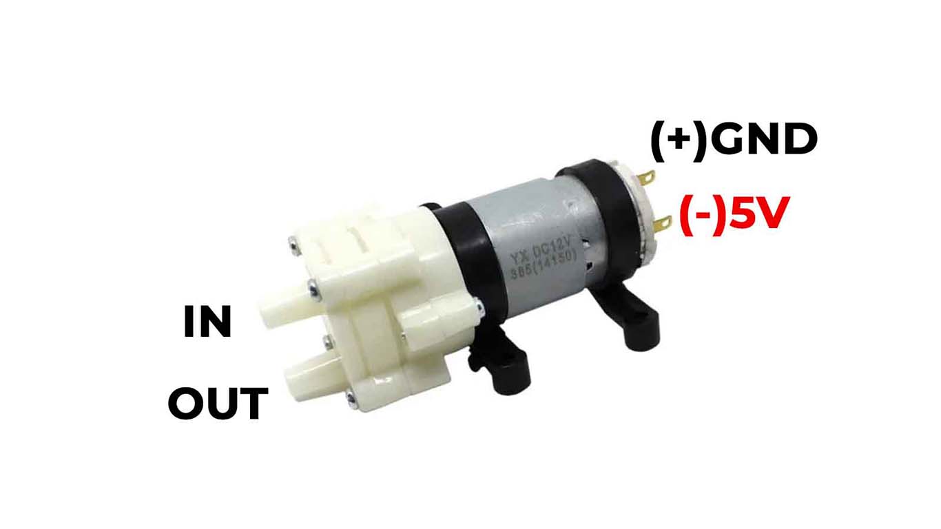
1. One of the difficulties that we were able to observe when making the machine is how to be able to work with liquids on these machines so that they function correctly and do not affect the circuits so much. Therefore, we did research on peristaltic motors that helped us manage the liquid. We also had to find these liquid tubes that can transport the liquid and in the end we were able to make them work without affecting the machine due to the liquids.
2. Another difficulty was how to work with the stepper motor. It is the first time that everyone in the group did not know how to start programming and what components are needed for its operation. For this reason, we started to find out and also asked some colleagues for help so that they could support us in this.
3. Other difficulties we have is the lack of materials at hand that can facilitate or save time for progress. Many of the components had to be purchased in places far from the FAB LAB and it was very difficult for us to find some of them. Despite this, we were able to carry out the design and operation.
4. We encountered difficulties in programming and the lack of some specific components that we may need in our design so that it can function efficiently. We tried to solve some components that we couldn't find and the truth is that it worked, we were able to solve some limits or inconveniences that happened to us almost daily.
Project improvements
1. The machine works correctly, except that due to the lack of some components it remains very basic, but to improve it is to try to add more components that allow communication between components for better synchronization.
2. We could improve the design or the way we can connect different types of drinks so that just by placing a bottle or container, for example, it can work with any type of drink and be able to prepare different types for parties or meetings.
3. For the stepper motor, a shield and an Arduino UNO were used, the ideal would be to work with boards designed and manufactured by oneself. We consider that the XIAO RP2040 could handle the entire circuit and operation of this machine.
4. Finally, try to improve the connectivity of the containers or change the design to be able to receive whichever container or bottle is the most used.