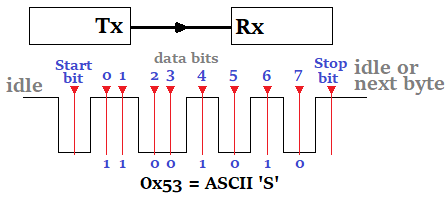
It's a method of data transmission that doesn't rely on an external clock. It involves various elements such as baud rate, synchronization bits, data bits, and optional parity bits. A TX (transmitter) to RX (receiver) connection is used for point-to-point communication between devices.
Asynchronous serial communication is a communication interface in which the signals used are not synchronized to each other using a common clock signal. Instead, start and stop bits are used to indicate the beginning and end of a data message. This type of communication utilizes a point-to-point type of interface, meaning that only two devices can be linked together to communicate. These two devices must also agree upon the rate at which bits will be transmitted and received, known as the baud rate, since there is no clock signal to indicate such transitions. Furthermore, asynchronous serial communication can be implemented in either a full-duplex (independent transmit and receive lines) or half-duplex (shared transmit/receive line) configuration, making it a versatile communication protocol that can be used in many different applications.
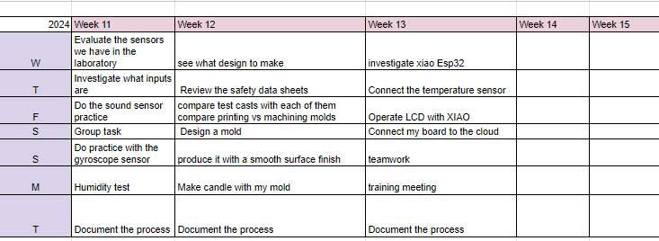
BAUD RATE:
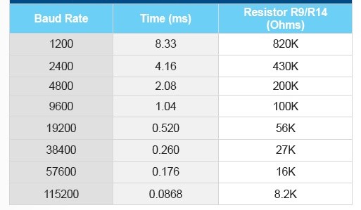
An important parameter when using asynchronous serial communication or when interfacing with a UART is how fast data can be transmitted across a serial line. The number of bits per second sent over a UART is defined as the baud rate. Possible baud rates span a wide range and can be almost any value, but since both devices must support the same baud rate, certain values have become standard baud rates. As the baud rate increases, the amount of time required to send or receive data decreases. Table 4.1 provides a list of standard baud rates and the amount of time required to transmit 100 bytes of data using the standard 8-N-1 configuration (requiring 10-bits per byte of data).
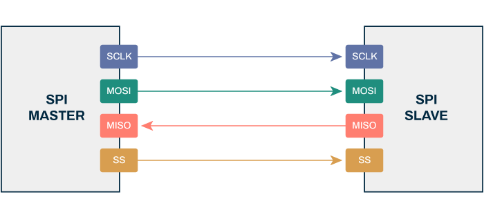
SPI (Serial Peripheral Interface)
It's a synchronous protocol used for communication between electronic devices. It involves a master-out-slave-in (MOSI) line and a master-in-slave-out (MISO) line, along with a clock line and a slave select line. It's suitable for high-speed communication over short distances.
The SPI communication protocol consists of four lines in addition to the ground, these are:
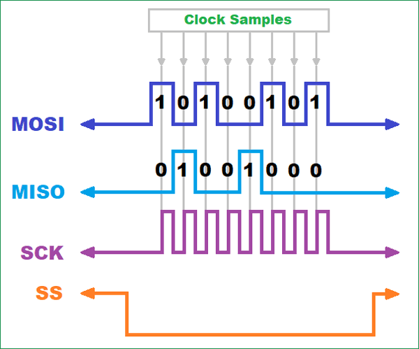
SCLK - Serial clock (Output from master): For communication to take place between both devices that are going to communicate, both the Master and the Slave must be synchronized in their clocks. This will also determine something of utmost importance and that is whether the information is sent in the rising or falling edges, this protocol within its composition has four modes, distributed according to whether the sending is made on the rising or falling edge and at what value the clock starts.
MOSI - Master Out Slave In (Data output from master): Master Input Slave Output, this port is responsible for the Master receiving information from the Slave.
MISO - Master In Slave Out (Data output from slave): The MOSI stands for: Master Output Slave Input; This port is responsible for allowing the Master to send information to the slave.
SS or CS - Slave select or Chip select (often an active-low signal, output by the master): Called Slave Selection, this port allows the Master to know which of the multiple Slaves it has it wants to send the order to send information to.
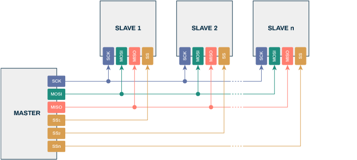
The SPI standard architecture typically consists of one master device and multiple slave devices that the master communicates with, which means that one set of data lines can be connected to multiple slave devices. However, the slave selection is quite different from I2C. The number of slave devices that can be used in an SPI communication protocol network is limited by the number of SS (Slave Select) or CS (Chip Select) pins you have available
I2C (Inter-Integrated Circuit)
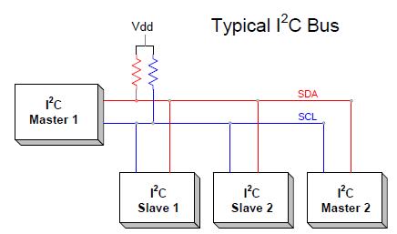
I2C is a serial communication protocol that is based on data transmission over two lines: SCL and SDA. SCL is the clock line, which is used to synchronize data transfer. SDA is the data line, which is used to transmit the actual data.
I2C is a master-slave protocol. An I2C device can be a master or a slave. The master initiates communication and controls the data flow. The slave responds to the master's requests.
SCL (System Clock) is the line of clock pulses that synchronize the system.
SDA (System Data) is the line through which data moves between devices.
Common GND (Ground) of the interconnection between all devices "hooked" to the bus.
The SDA and SCL lines are of the open drain type, that is, a state similar to open collector, but associated with a field effect transistor (or FET). They must be polarized in a high state (connecting to the power supply through "pull-up" resistors), which defines a bus structure that allows multiple inputs and outputs to be connected in parallel.
Definition of terms:
Maestro (Master): Device that determines the times and direction of traffic on the bus. It is the only one that applies the clock pulses on the SCL line. When several master devices are connected to the same bus, the configuration obtained is called “multi-master”.
Slave: Any device connected to the bus that does not have the ability to generate clock pulses. Slave devices receive command and clock signals generated from the master.
Bus Free: State in which both lines (SDA and SCL) are inactive, presenting a logical high state. It is the only time a master device can begin to use the bus.
Start: Occurs when a master device occupies the bus, generating the condition. The data line (SDA) goes low while the clock line (SCL) remains high.
Stop: A master device can generate this condition, leaving the bus free. The data line and clock line take a logic high state.
Valid Data: Situation present when a data present on the SDA line is stable while the SCL line is at a high logic level.
Data Format: The transmission of data through this bus consists of 8 data bits (1 byte). Each byte transmitted to the bus is followed by a ninth clock pulse during which the device receiving the byte must generate an acknowledgment pulse.
Acknowledgment: The acknowledgment pulse, known as ACK, is achieved by placing the data line at a logic low level during the course of the ninth clock pulse.
Address: Every device designed to operate on this bus has its own unique access address, pre-established by the manufacturer. There are devices that allow part of the access address to be defined externally,
which enables a set of devices of the same type to be connected to the same bus, without identification problems. Address 00 is the so-called "general access" address; All devices connected to the bus respond to it.
Read/Write (R/W Bit): Each device has a 7-bit address. The eighth (least significant) bit sent during the addressing operation, completing the byte, indicates the type of operation to be performed. If this bit is high the master device reads information from a slave device. If this bit is low, the master device writes information to a slave device.
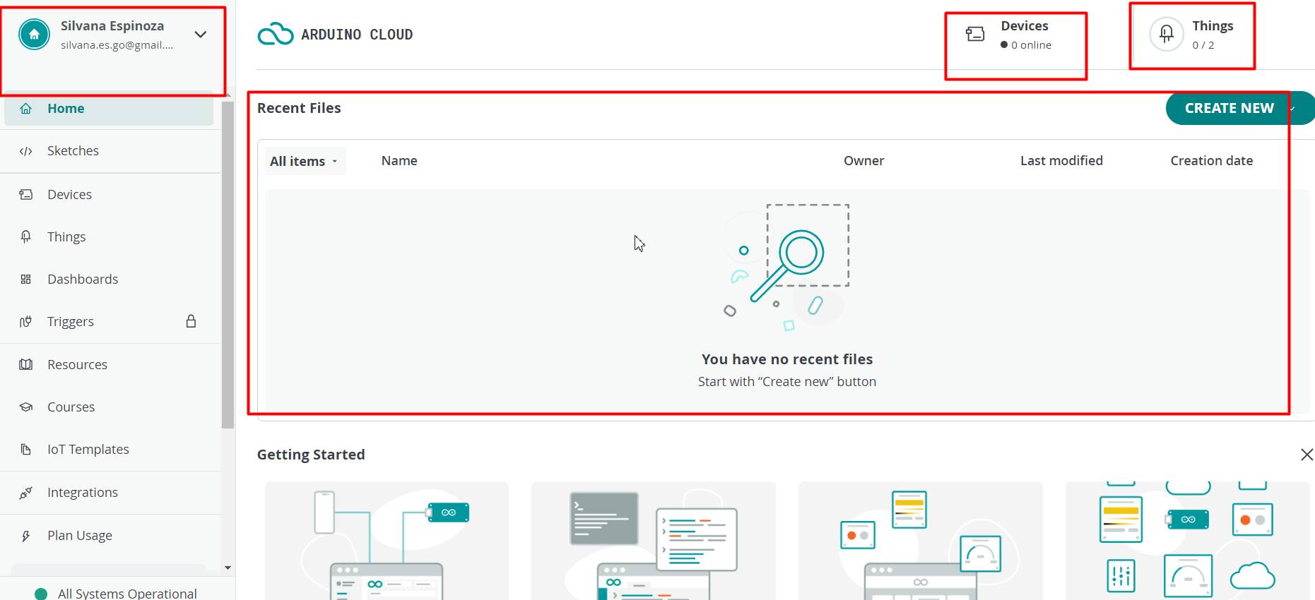
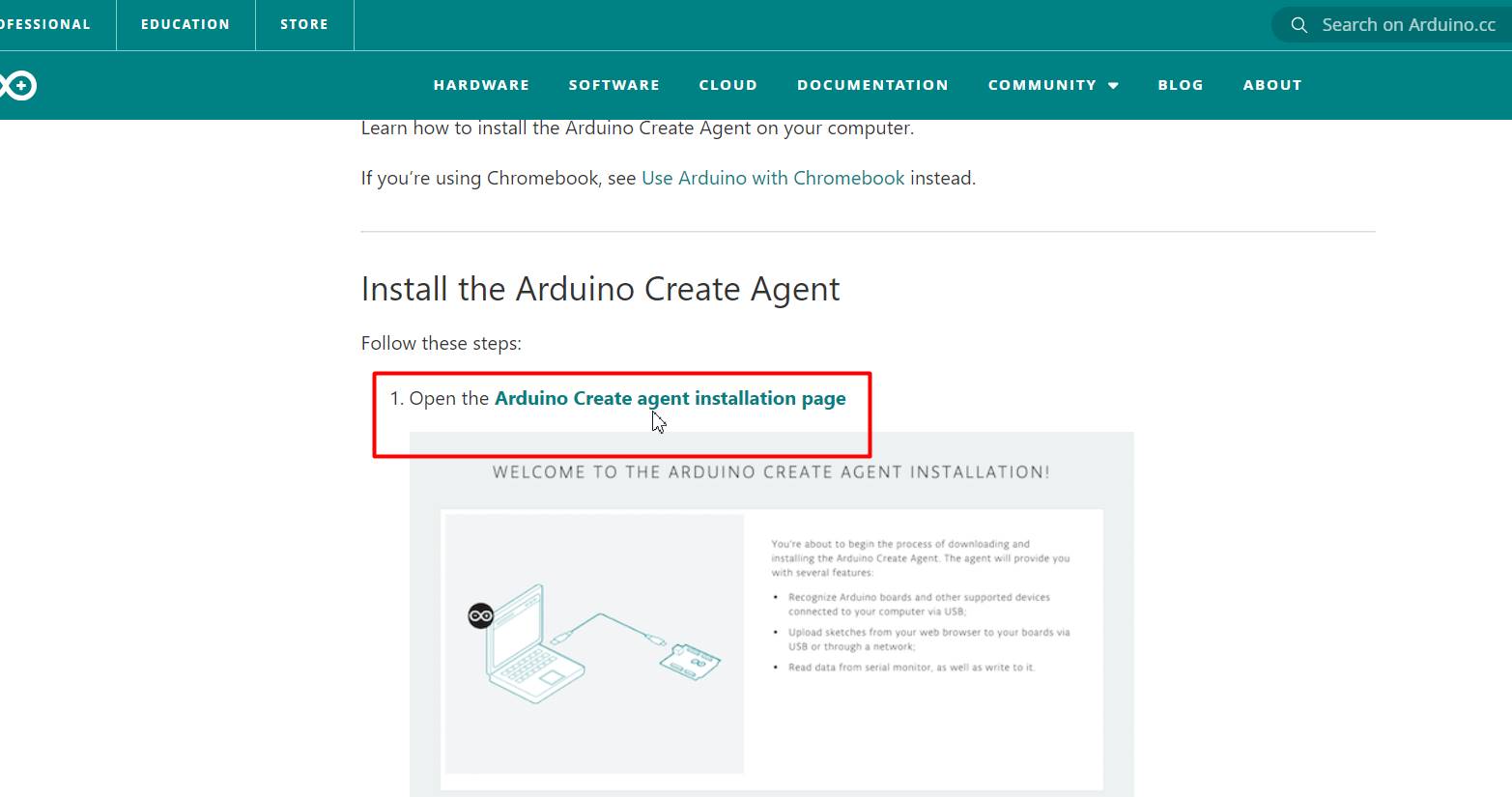
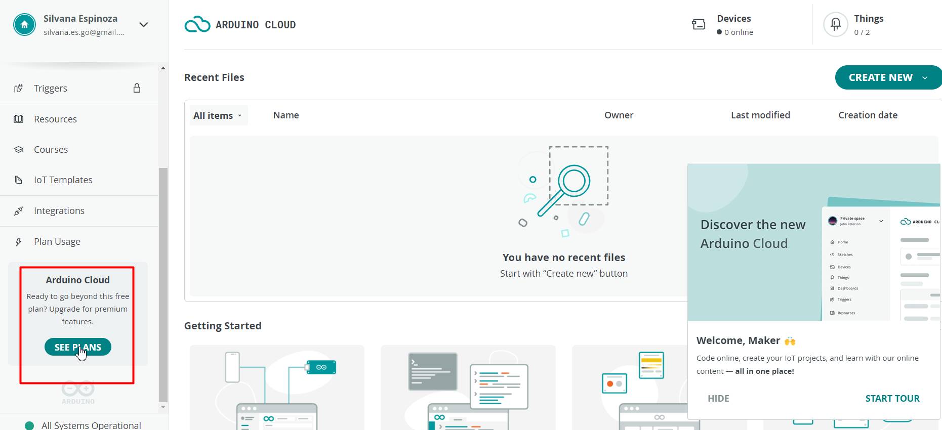
Create an Arduino Cloud account: Go to the Arduino website and create an account if you don't have one already. If you already have an account, log in.
Board
Connect your Xiao to the Internet: We will need a device compatible with WiFi or Ethernet connectivity to connect to the Internet. Make sure your device is properly connected to your WiFi network or via an Ethernet cable.
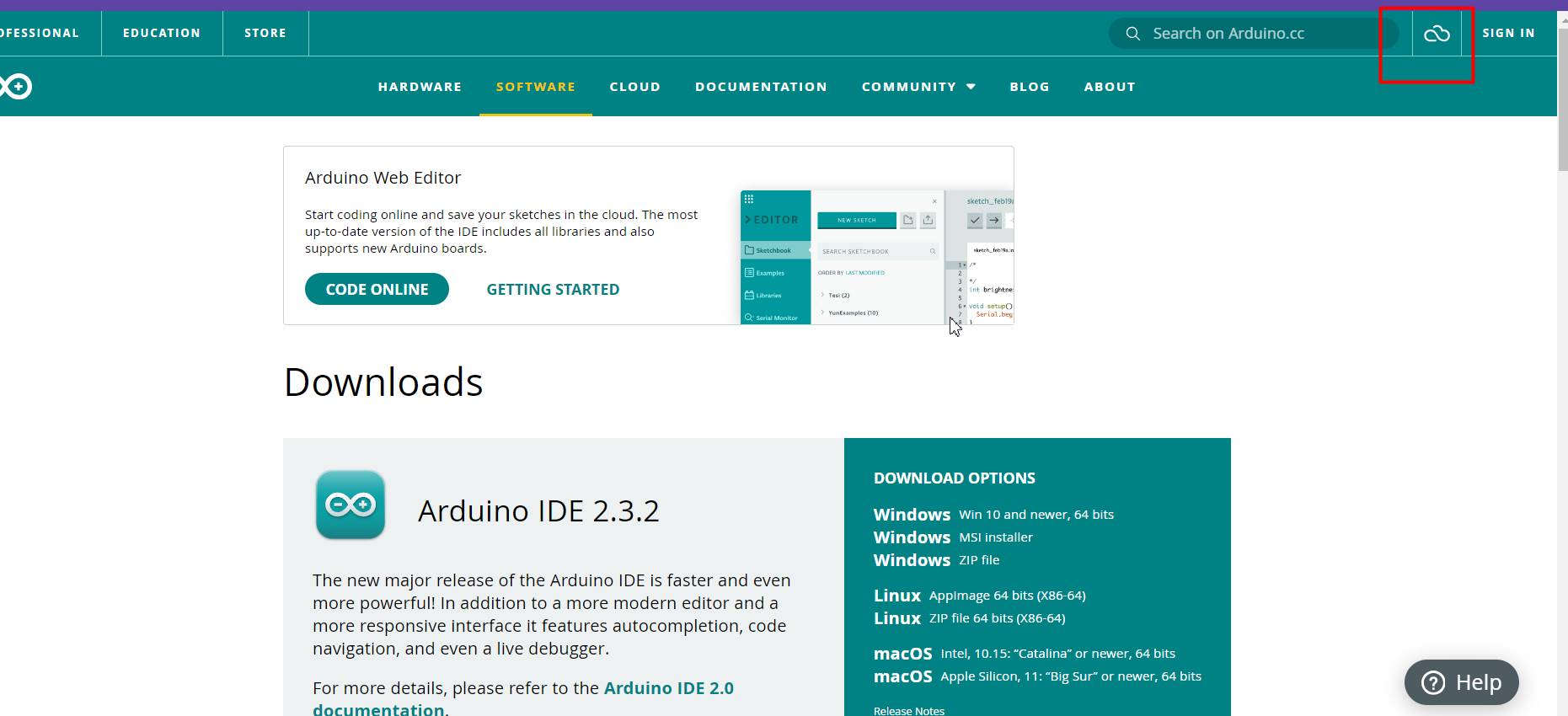
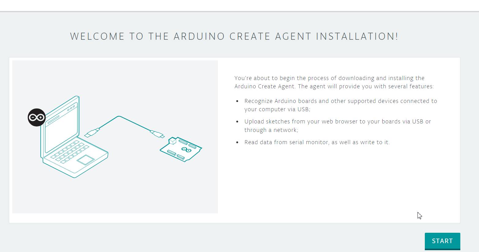
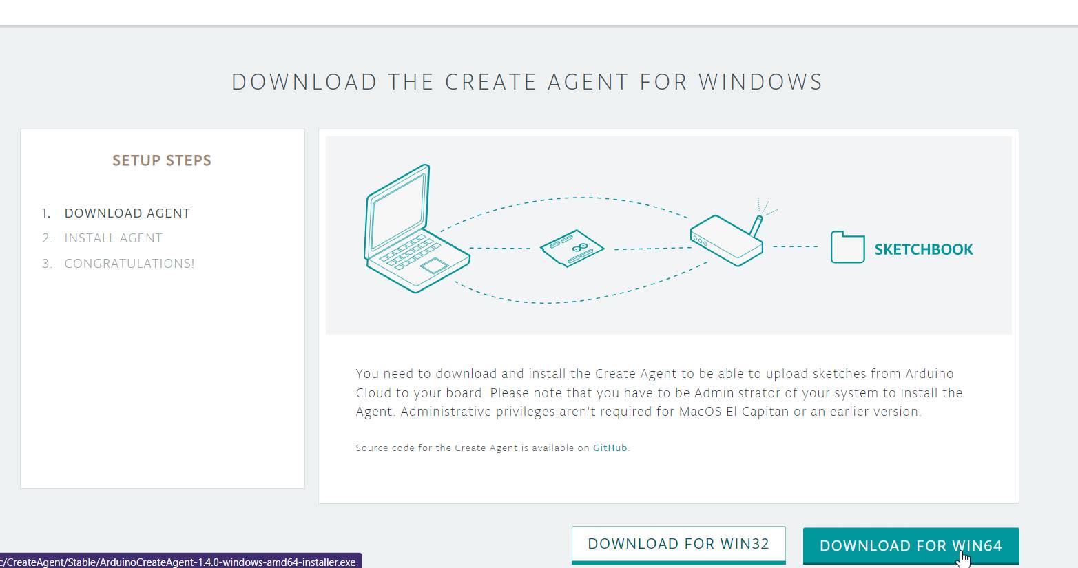
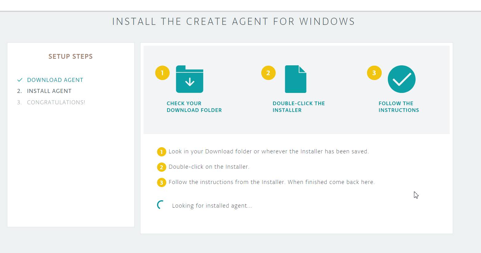
Set up your Arduino: Use the Arduino IDE software to program your Arduino. Make sure you have the latest version of the IDE installed.
Install the Arduino Cloud library: In the Arduino IDE, go to "Sketch" -> "Include Library" -> "Manage Libraries". Search for "Arduino Cloud" and click "Install" to install the library.
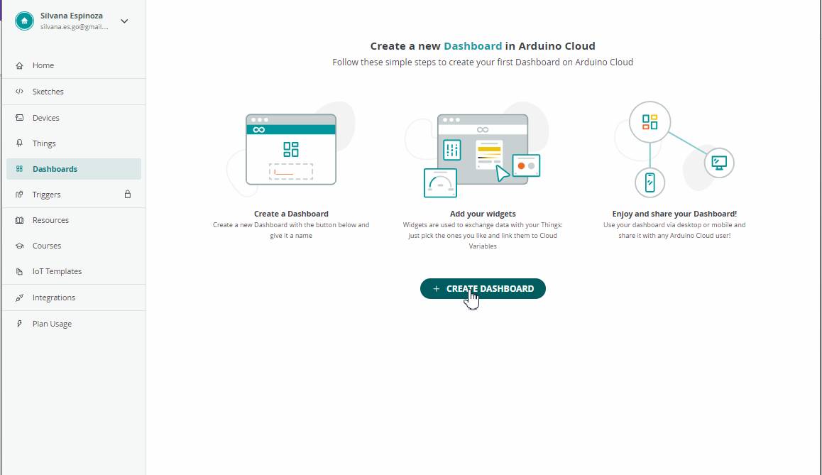
Create a new project in Arduino Cloud: Go to the projects section on the Arduino Cloud website and click "Create New Project." Give your project a name and follow the instructions to set it up.
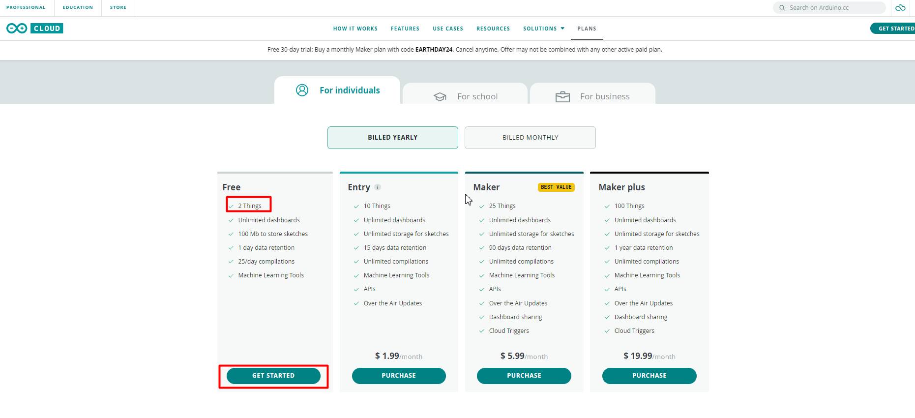
Here we can see the plans that Arduino has, but it also has its free plan.
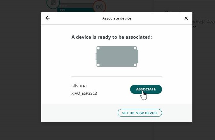
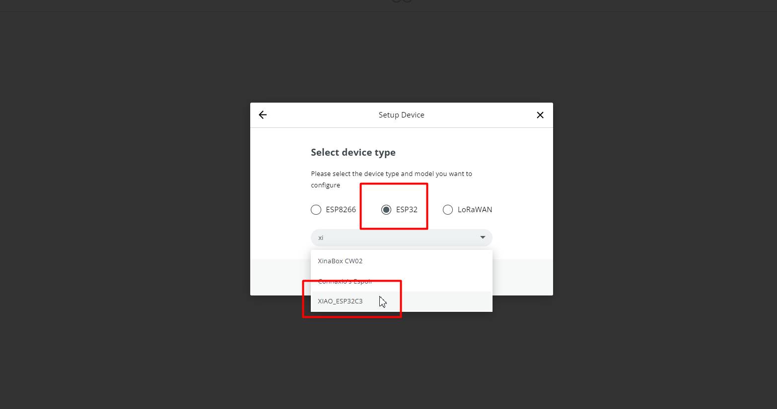
We associate the XIAO ESP32 C3, to connect our board
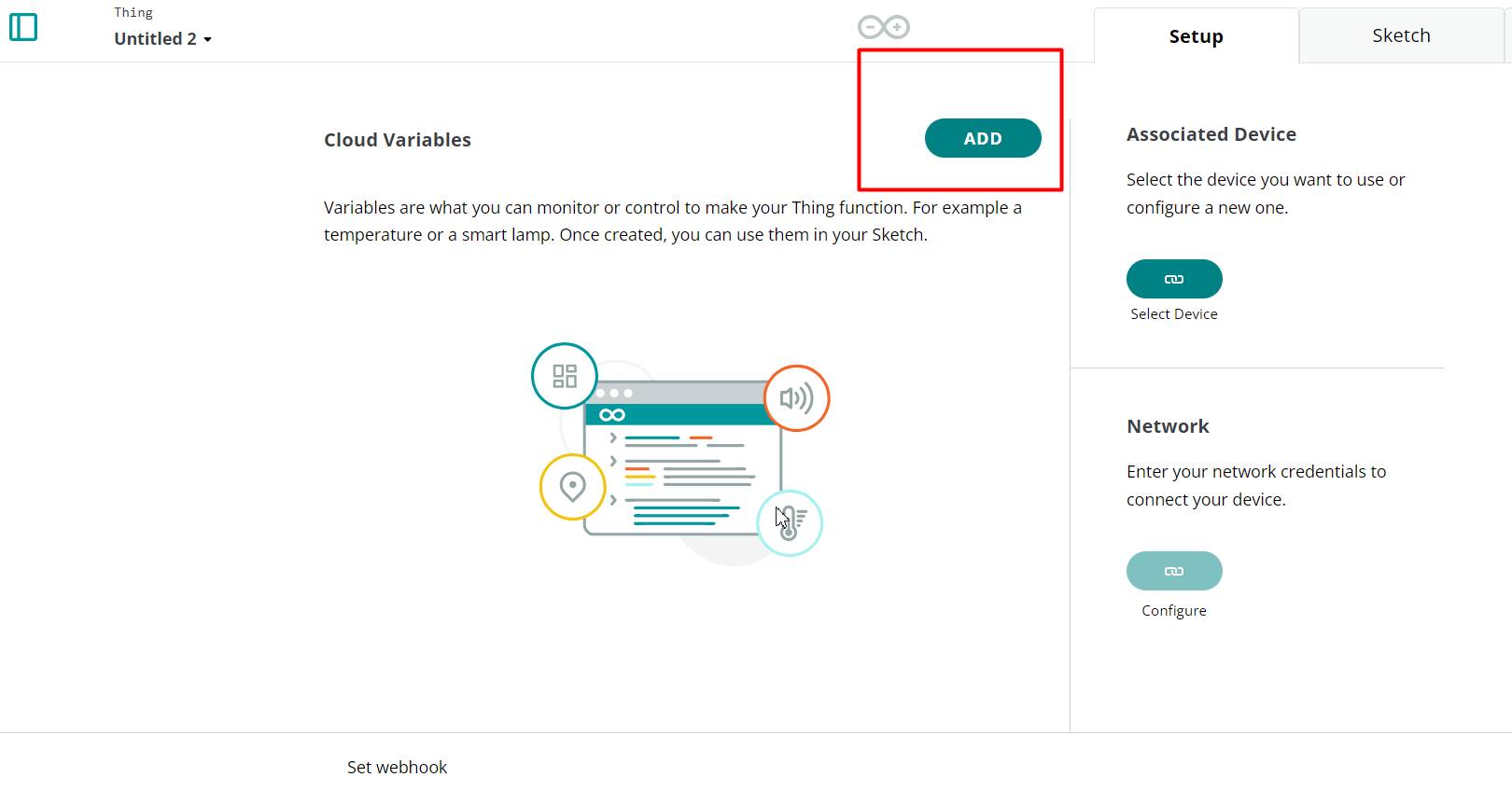
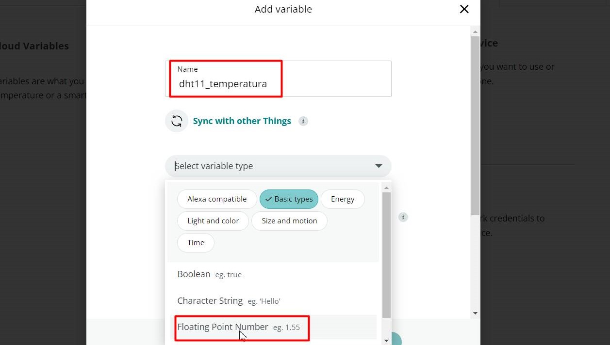
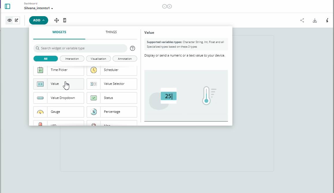
Variable
We add the variables according to the sensors you will use, in my case I will use the DTH11
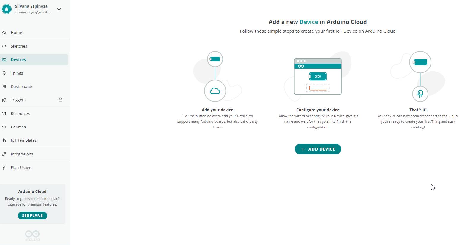
We add the device
We add the Esp32
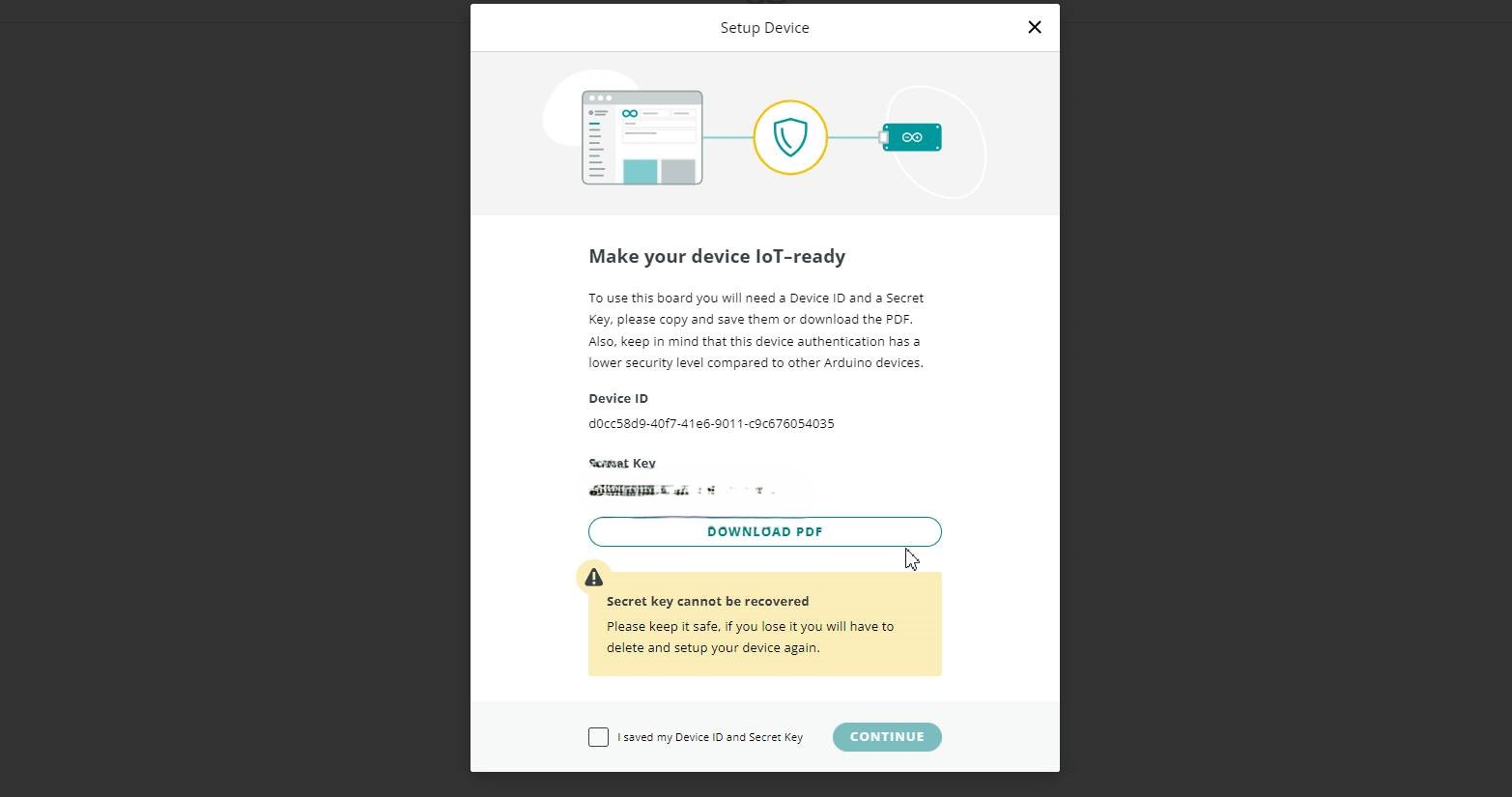
Make your device IoT, To use board you will need a device ID and a secret key.
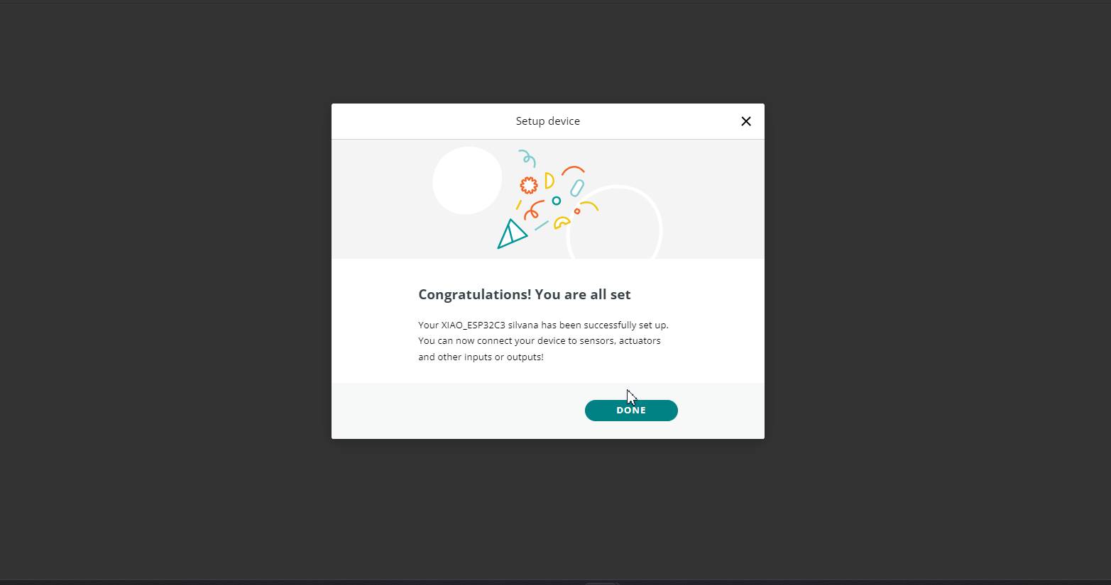
Ready!
If you got this far, that's fine, but I'll tell you that I created the variables again because I first connected to my home's Wi-Fi...
and then I did the steps again
You can see it in these steps so you can review it again...
successes!
WiFi connection
Device status history
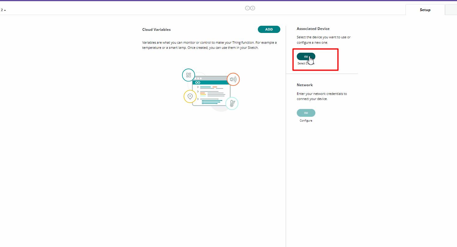
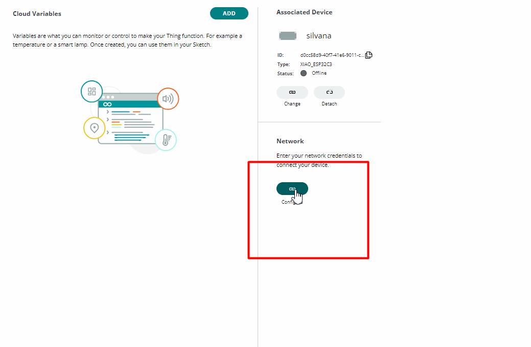
Select device you want to use or configure a new one
Associate
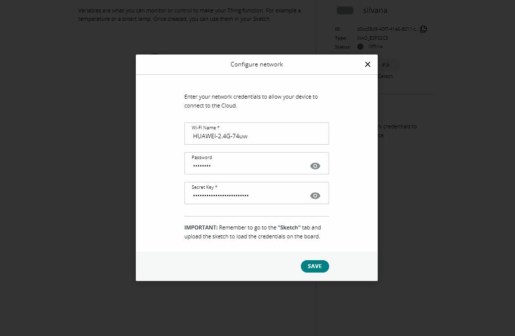
Network: Enter your network cdredentials to connect your device.
Here the wifi and the password, here also place the key.
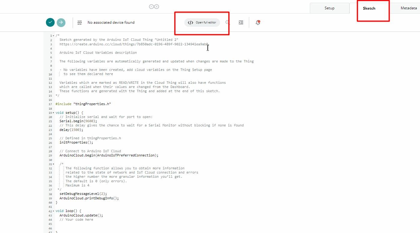
Open full editor
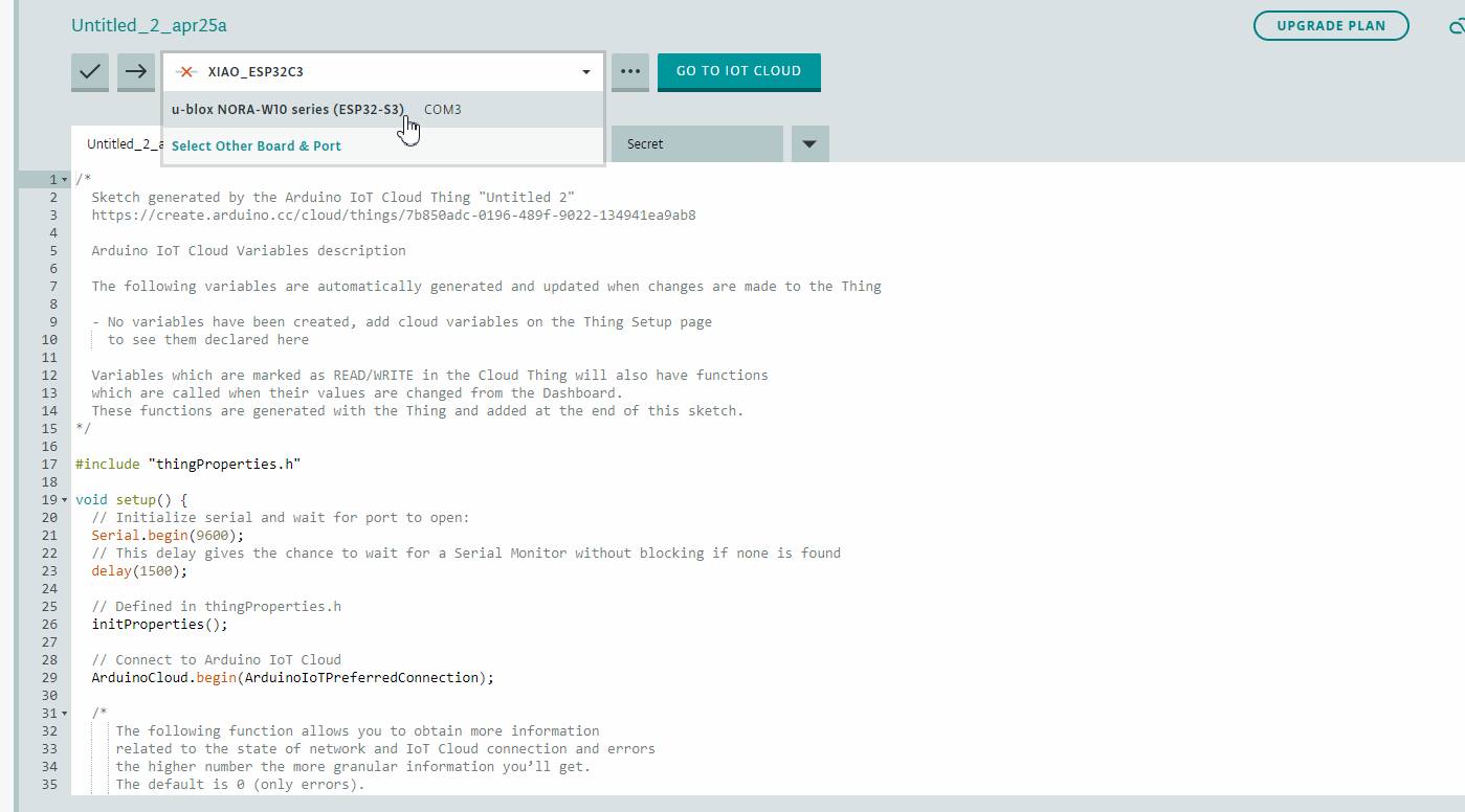
Connect the device, in my case Xiao
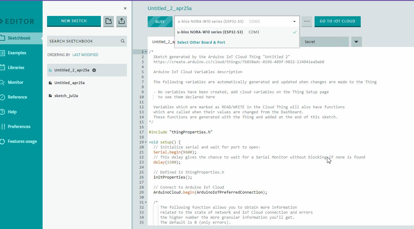
Now in full editor I connect u-blox Nora W10 series
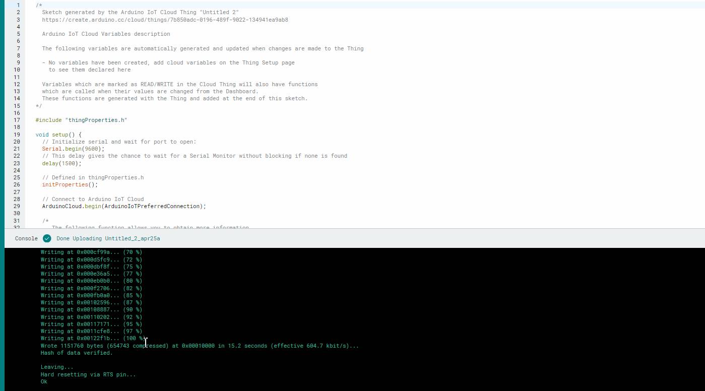
We give it a check to see that the code is correct.
Here we can see that I am already charged at 100%
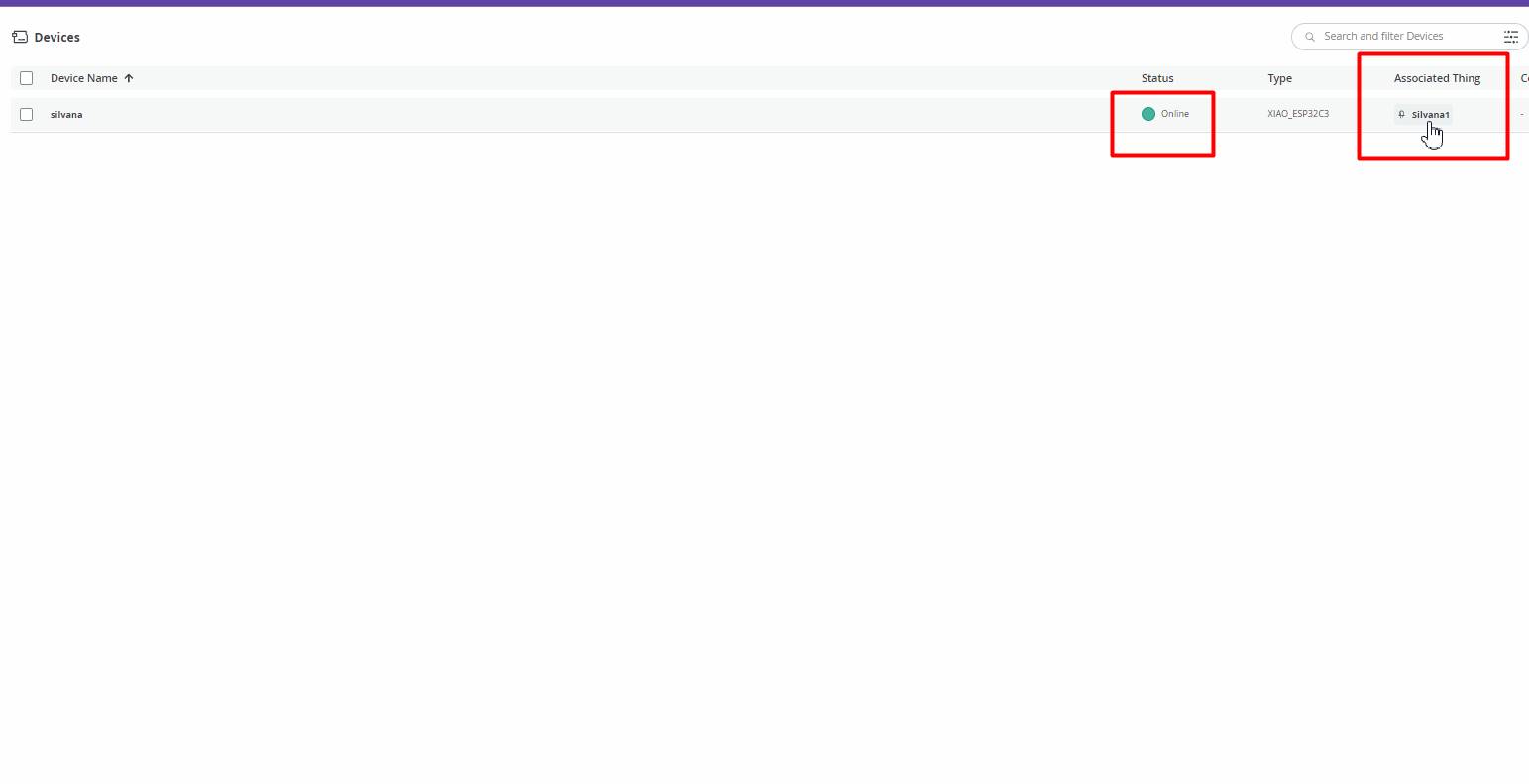
We can see that it is already online.
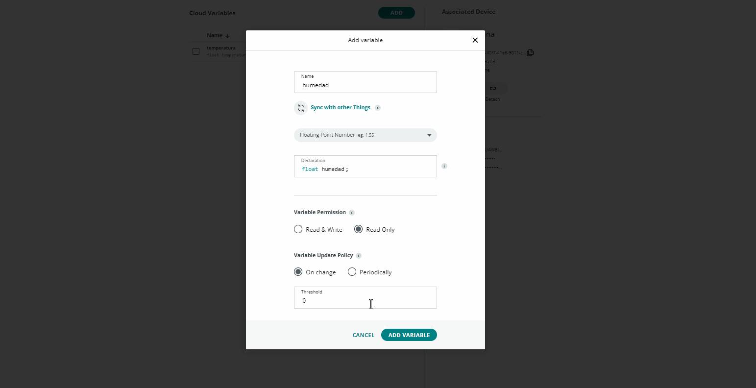
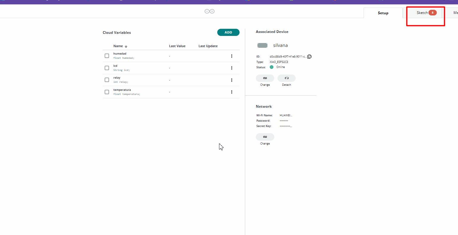
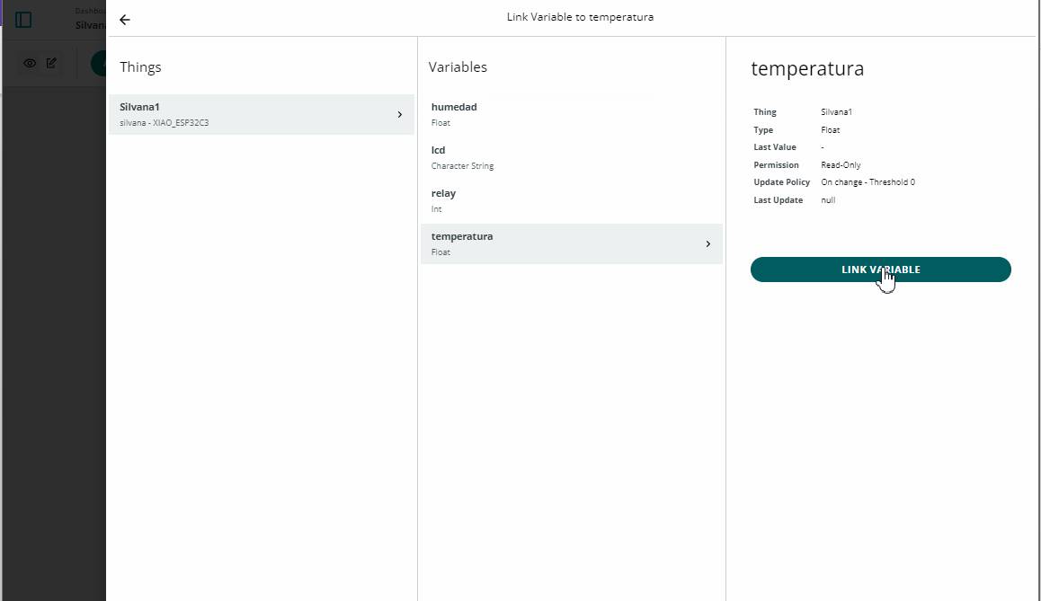
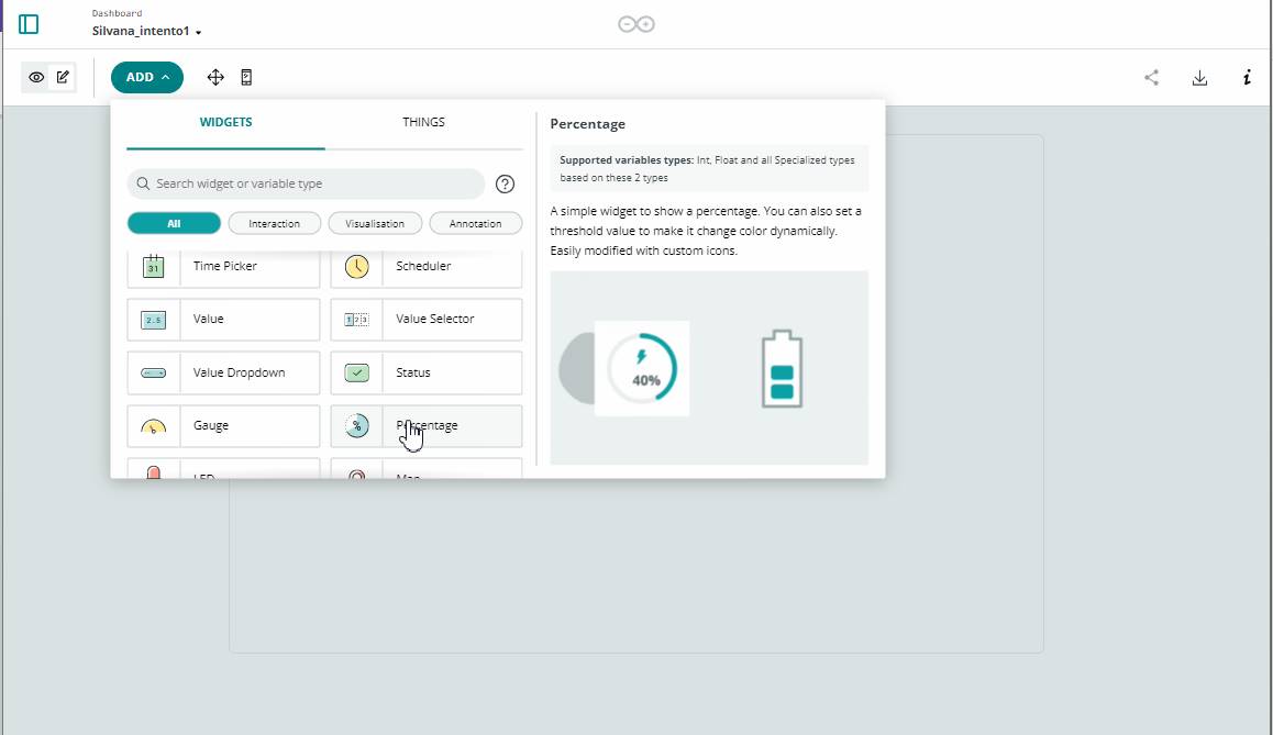
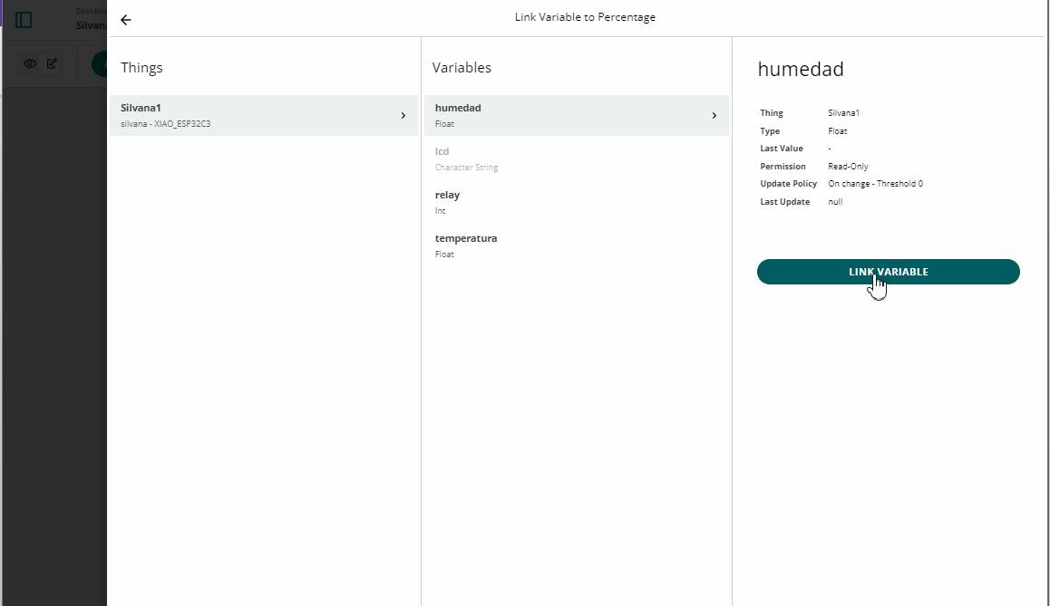
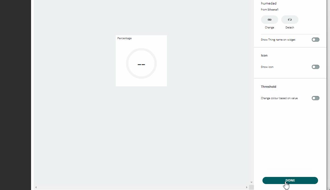
Here we add the new variables
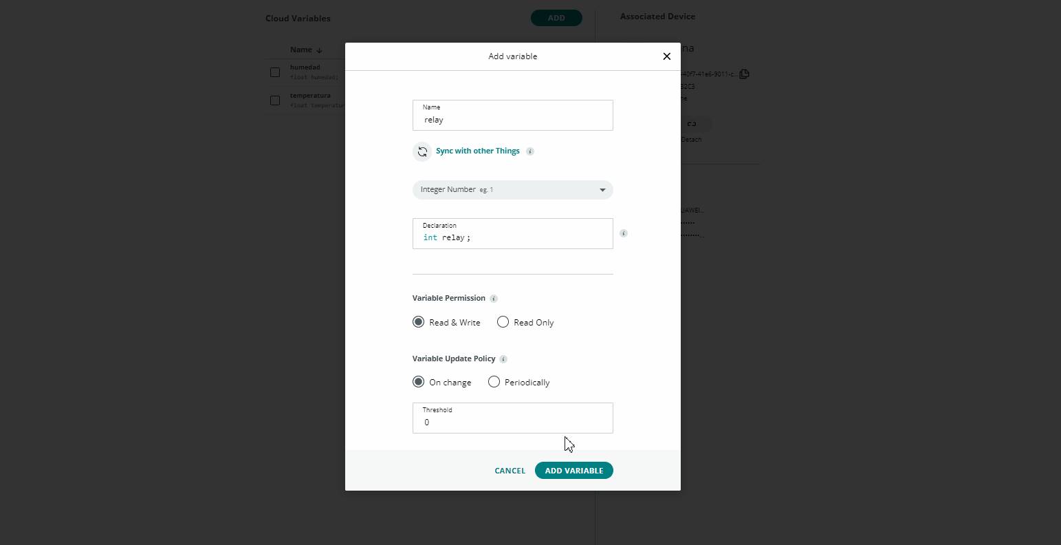
Here the relay variable
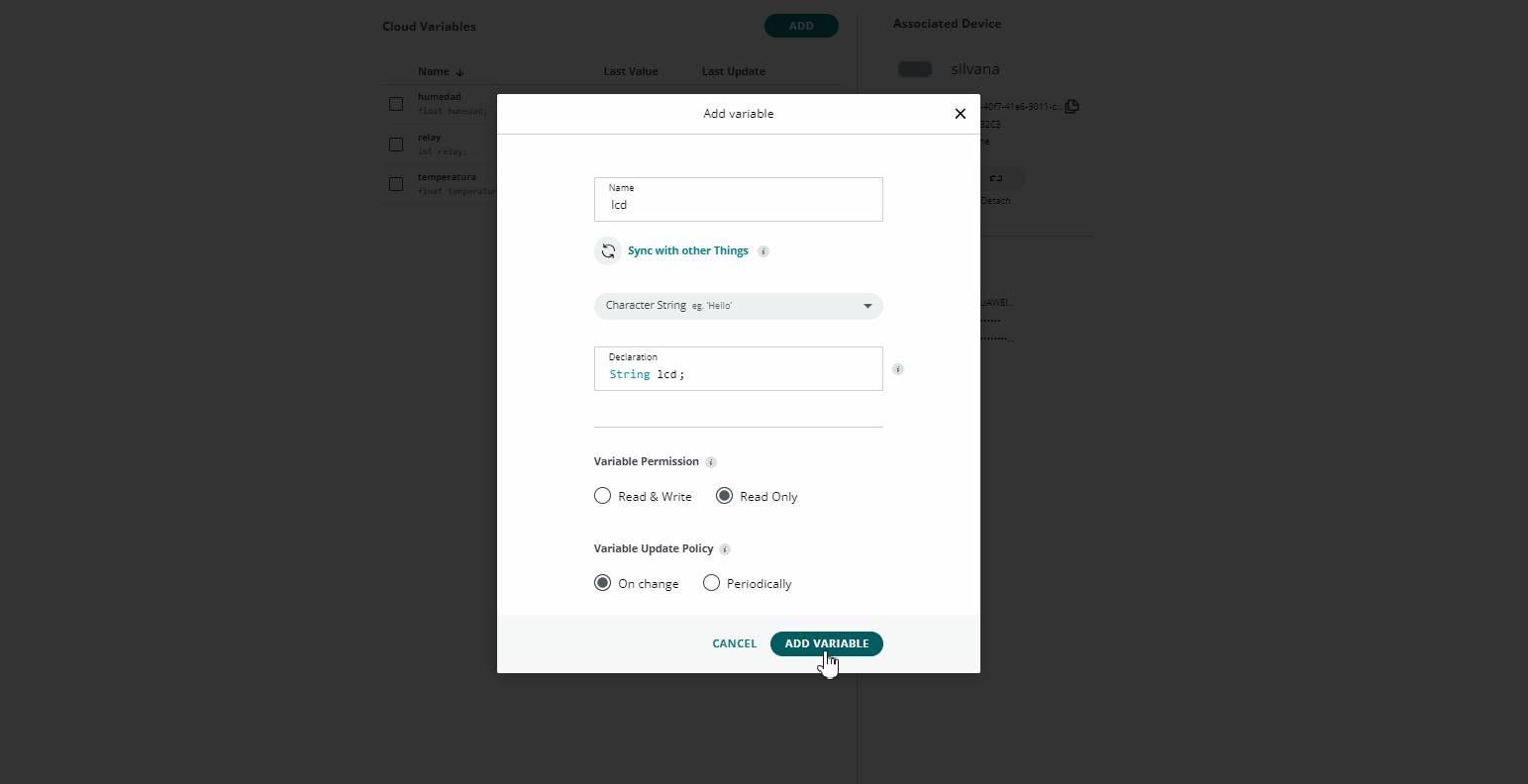
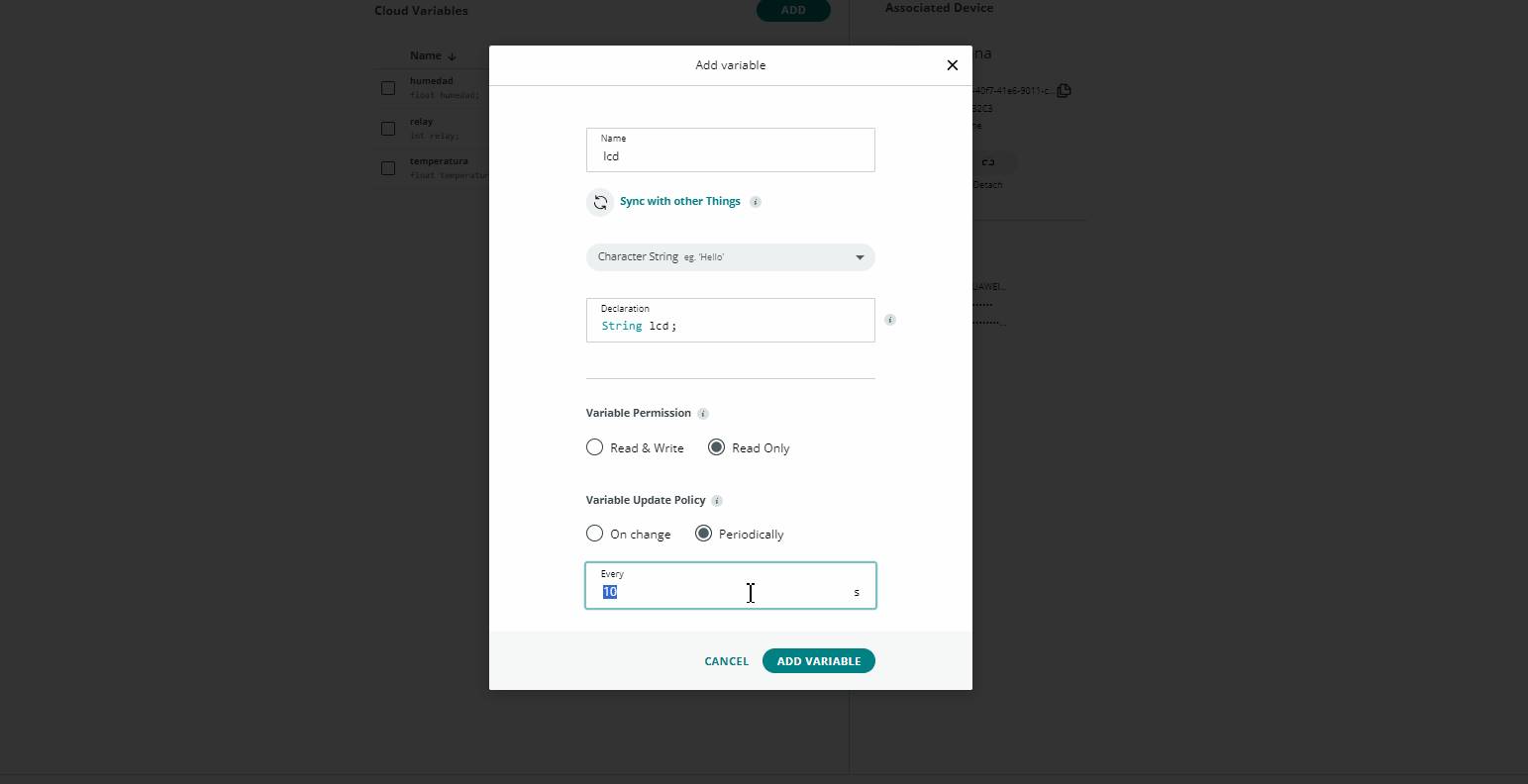
Here the LCD variable
We add Declaration String LCD, variable permission Read Only
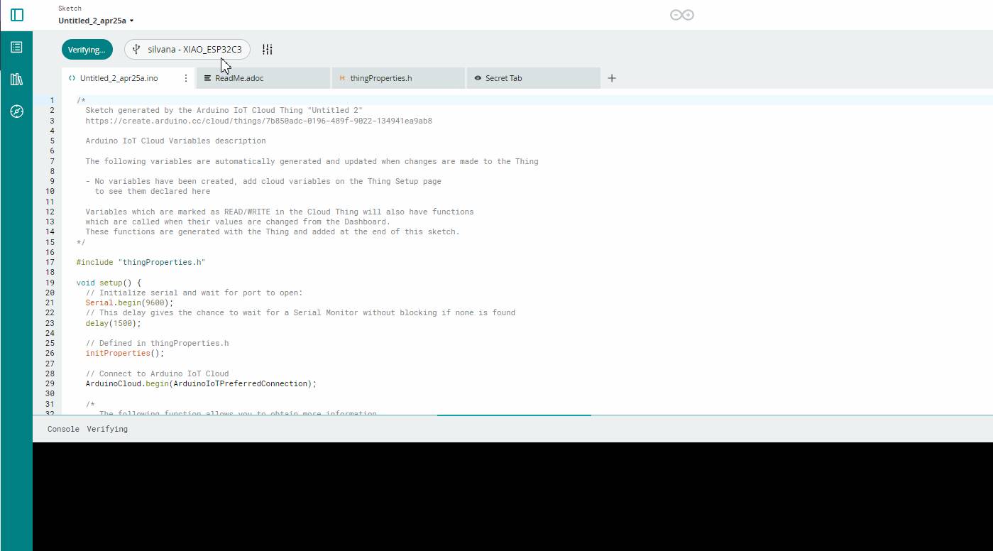
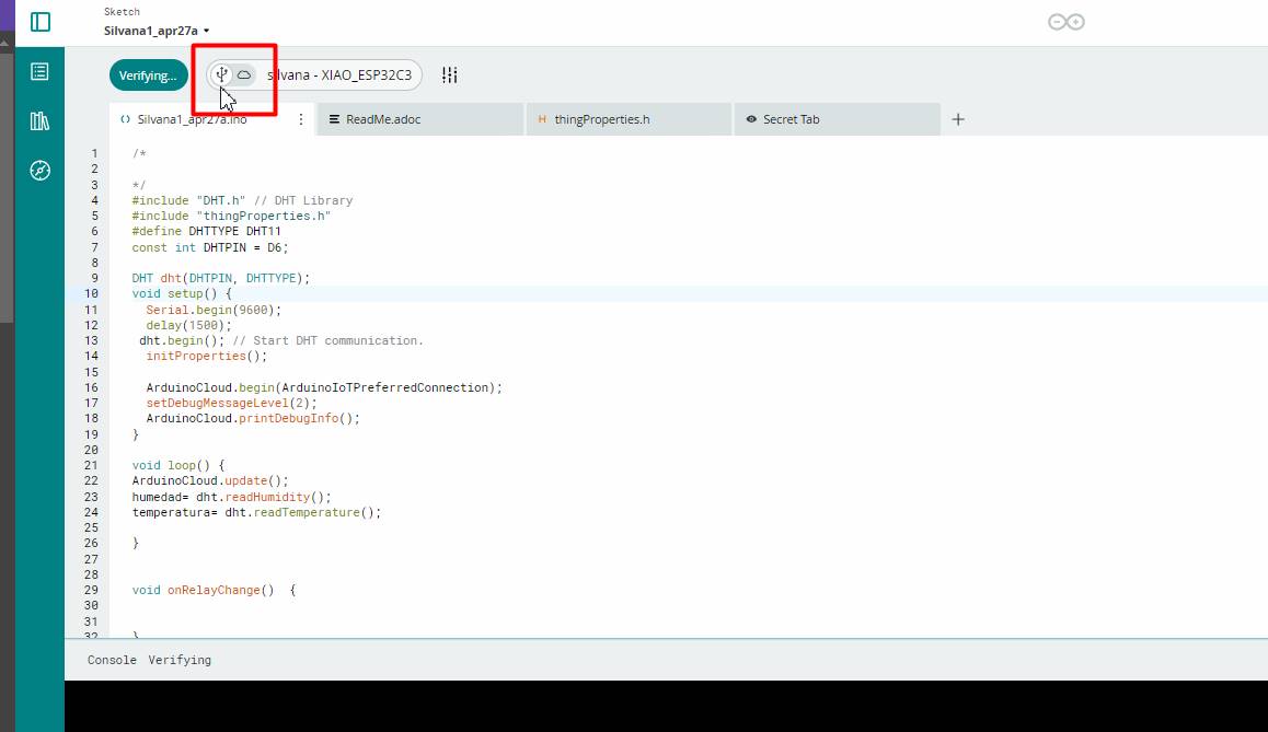
We click on Sketch after verifying that the Network is ready and the Associated Devices are ready
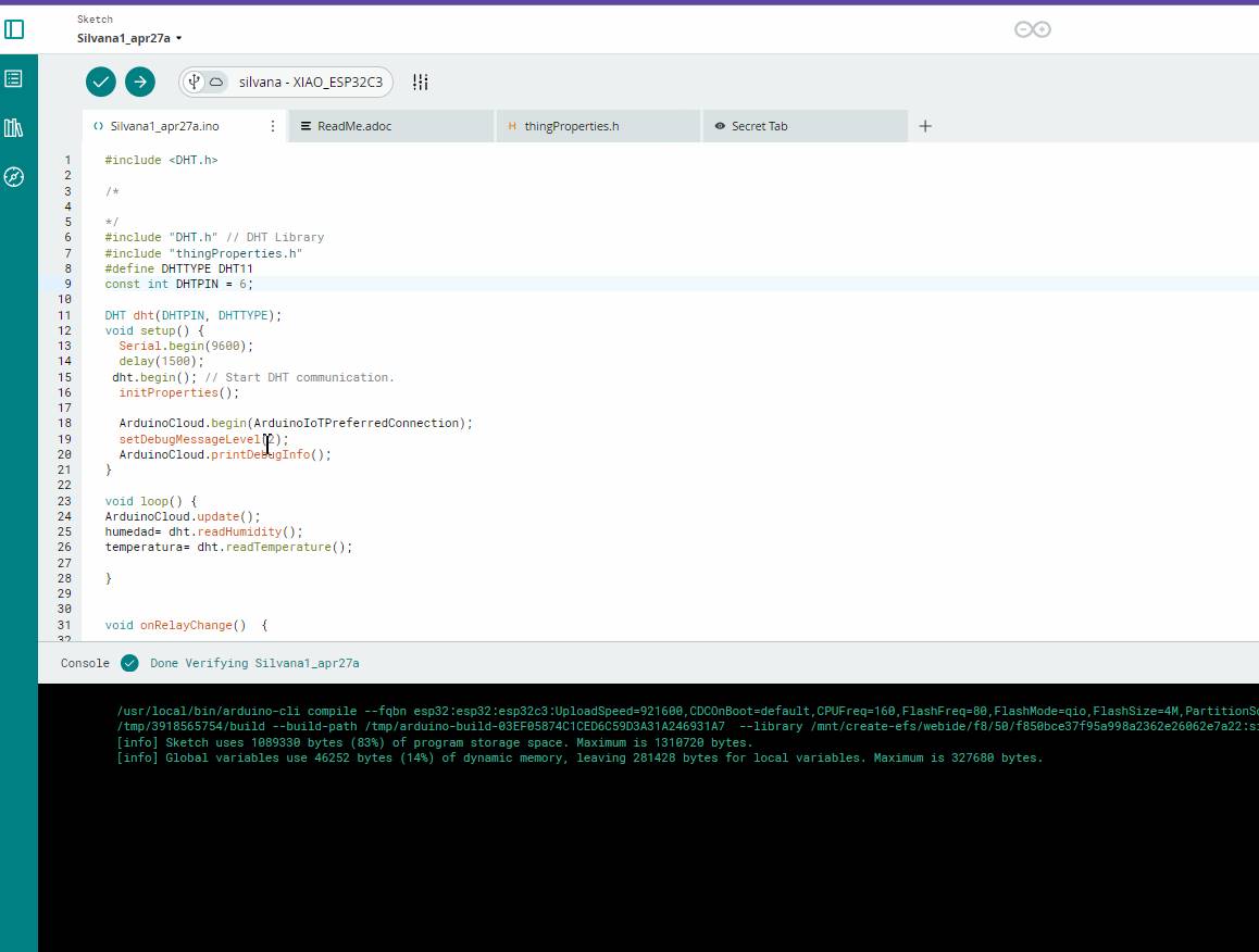
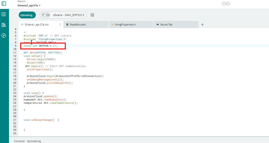
I place the DTH11 program according to the structure it gave me, do not delete what it says, otherwise it will replace some lines.
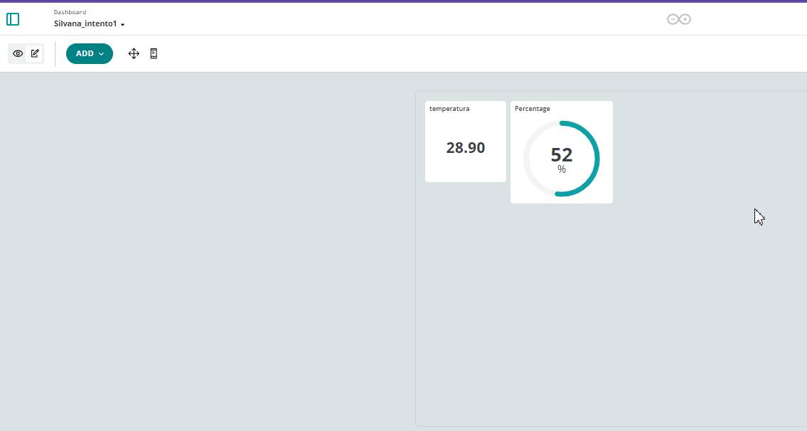
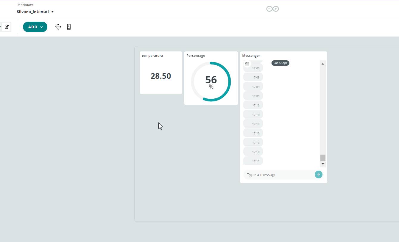
Now we connect with the USB to upload the program to the XIAO and be able to see the temperature and humidity, where we can see that, now I will explain.
In my group task I was able to turn my classmates' devices on and off.
With Hans I was able to turn a neopixel on and off with MQTT from my computer to his house.
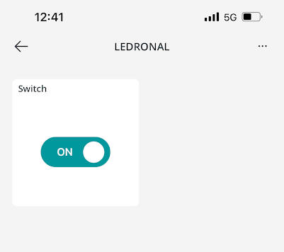
In the next one from the Arduino cloud applications I was able to turn on and off an LED from Ronal's project, as this was a Sunday Ronald had his device connected all the time and I could turn it on and off at any time, he even thought that I was not there connected and I was able to turn on its LED and he got scared, then he remembered that I had access, hahaha it was funny.
Wired connection
We connect Hans' board with mine, I as a slave to be able to use a motion sensor to detect and change the neopixel from green to red.
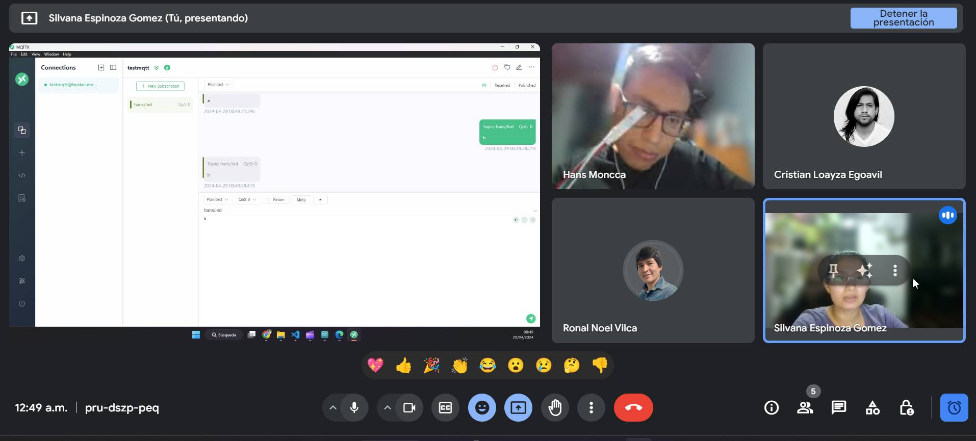
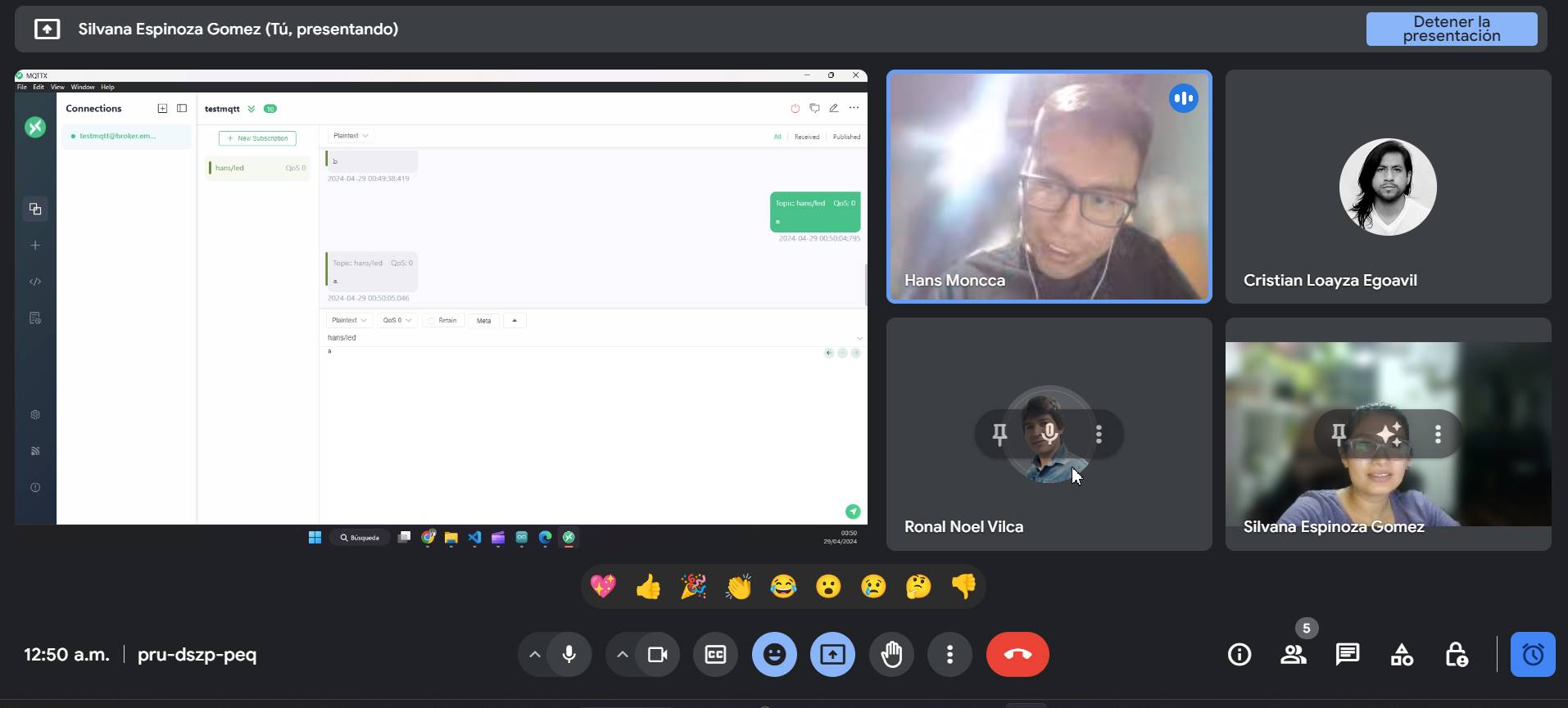
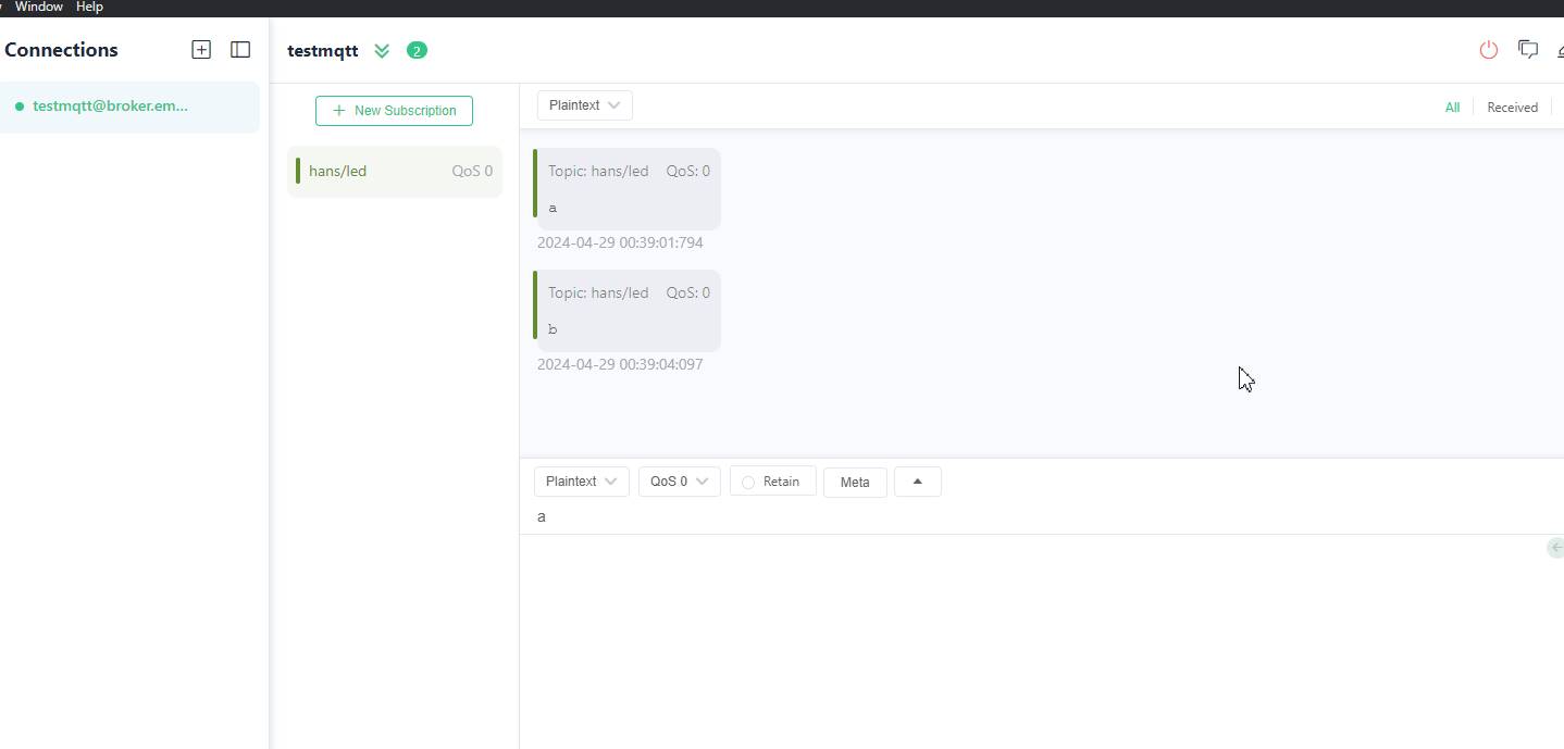
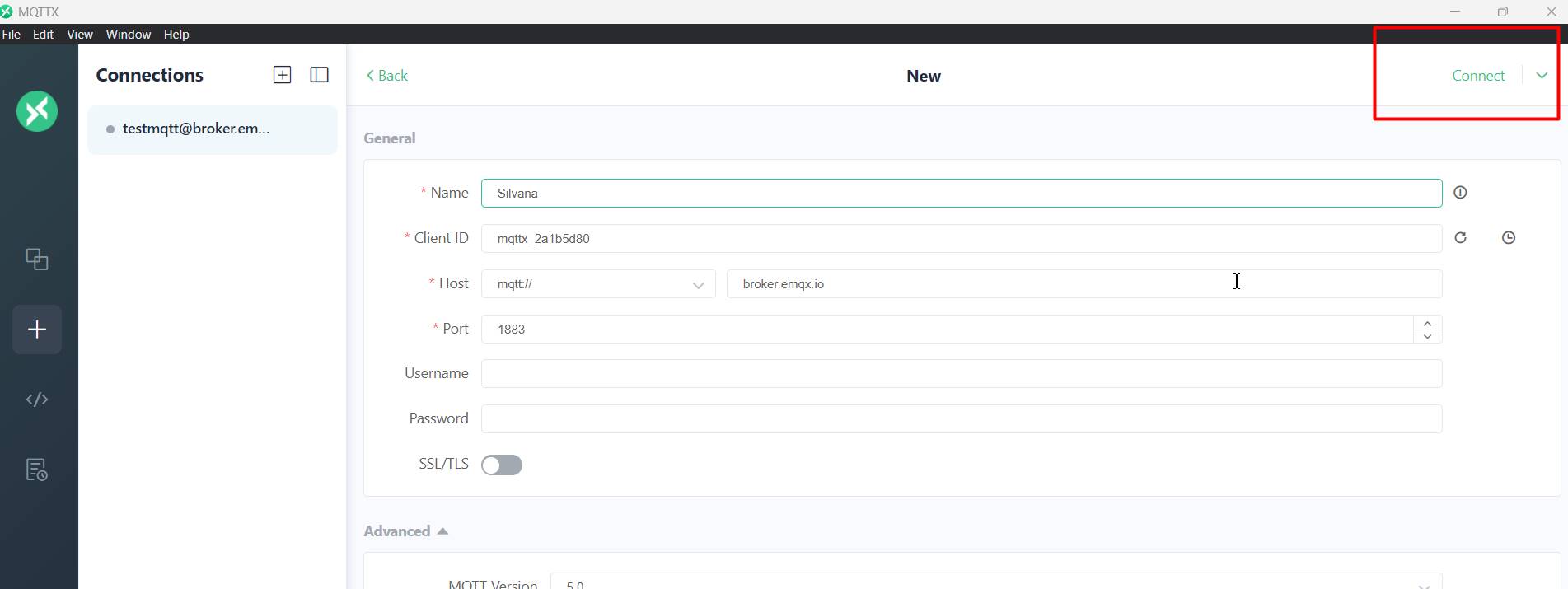
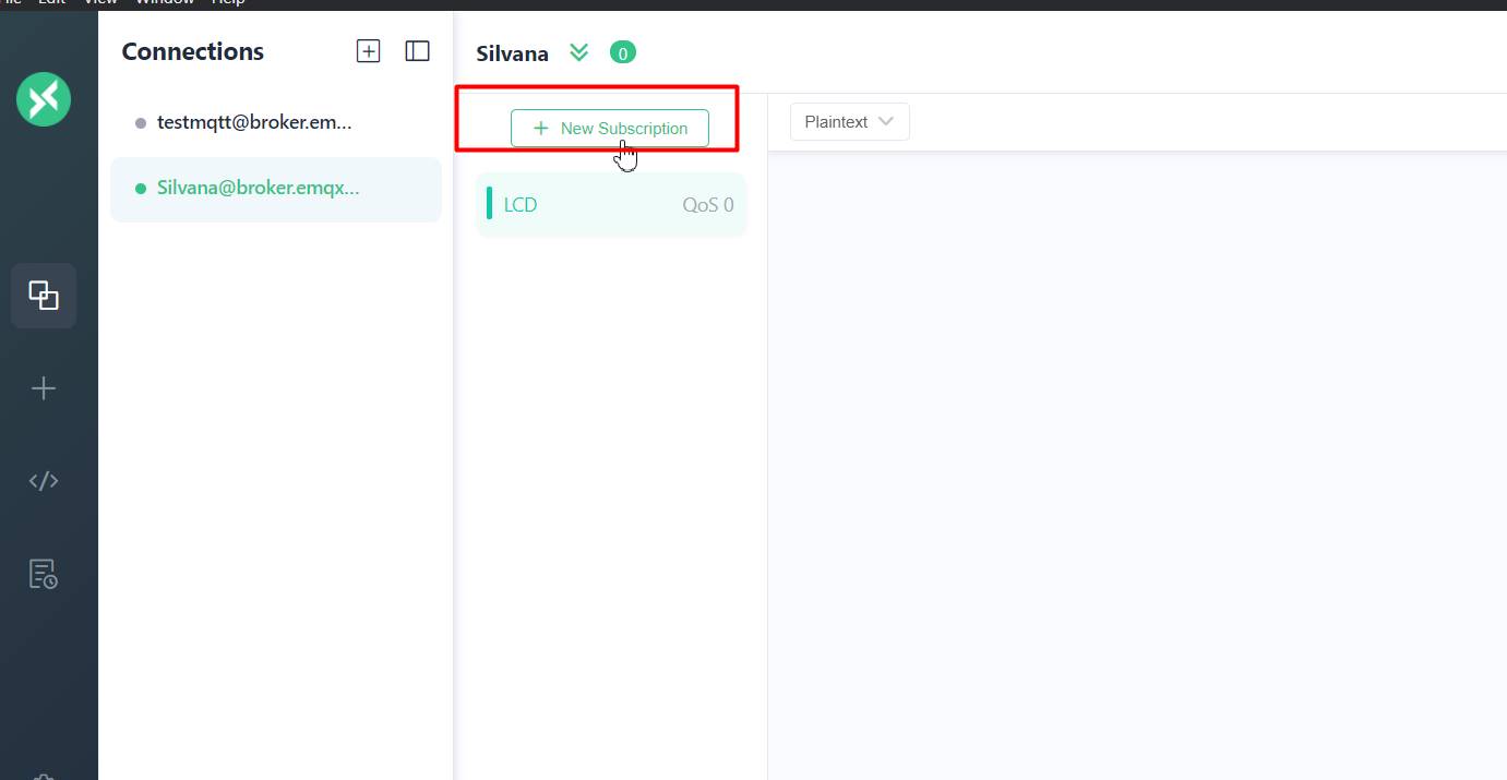
MQTTX is a cross-platform desktop application that makes it easy to connect and interact with MQTT brokers. It allows you to publish and subscribe to MQTT topics, send and receive messages, and monitor MQTT broker activity visually.
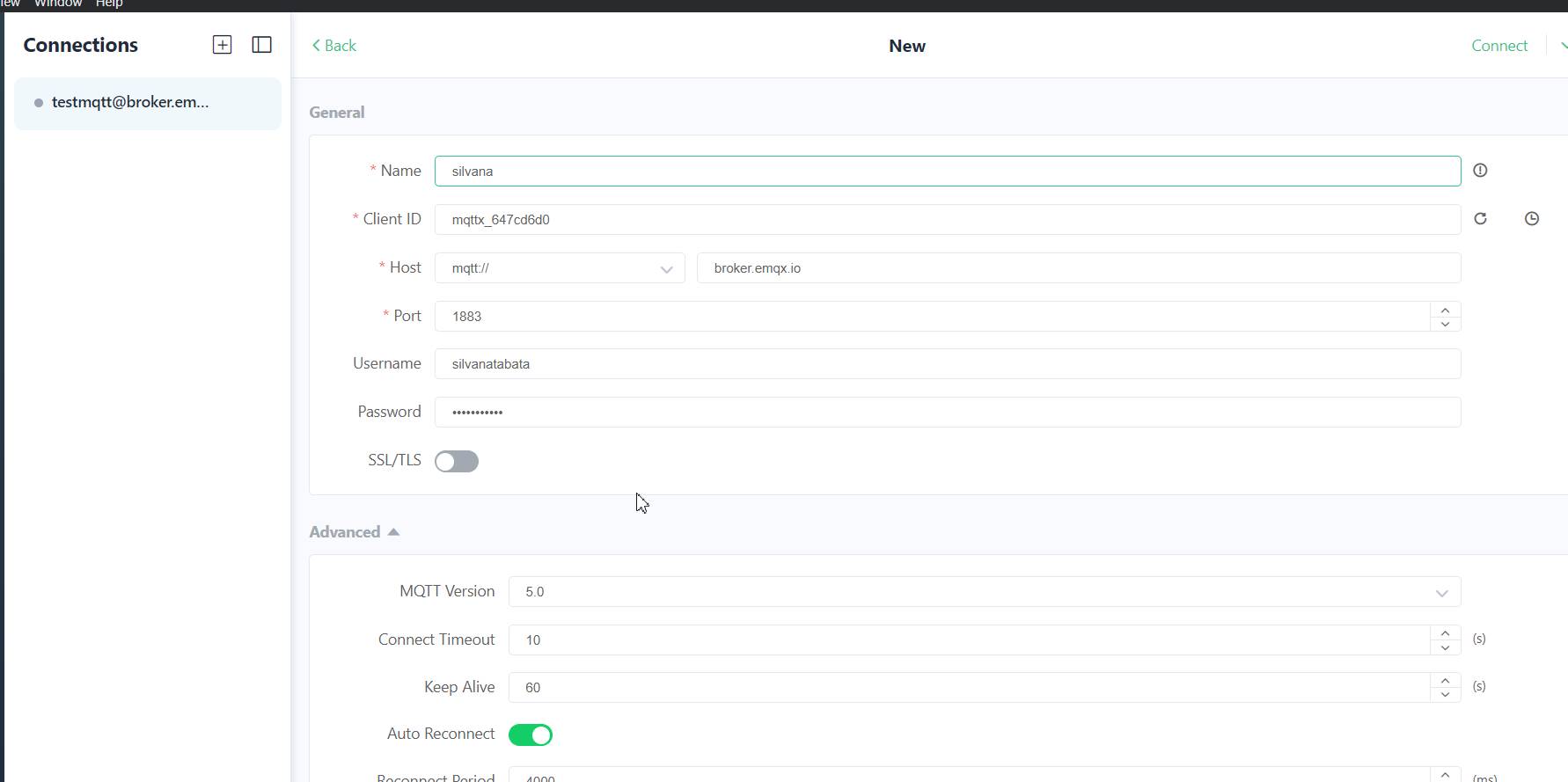
To use MQTTX, you first need to download and install the application on your computer. Once installed, you can configure it to connect to your MQTT broker. This usually involves providing the MQTT broker's IP address, port number, and, if necessary, authentication credentials.
The process involves the following:
Open MQTTX on your computer.
Connect MQTTX to your MQTT broker.
Post MQTT messages to the corresponding topic to control the neopixel of your partner's board, in my case hans.
Observe the response of the neopixel on your partner's plate when the message is received.
It is a powerful way to demonstrate remote communication between devices via the MQTT protocol.
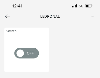
"a" was turned on and "b" was turned off
TEST WITH RONALD
Imagine that you are in Lima, your classmate, is in Huánuco. They are both working on projects for Fab Academy, but it turns out that you need to control Ronald's device from Lima for testing or demonstrations.
To achieve this, they have used Arduino Cloud, which is a cloud platform that allows the connection and remote control of Arduino devices over the Internet. Here's how it works in simple terms:
Connecting devices to the Arduino Cloud: First, Ronald has configured his Arduino device to connect to the Arduino Cloud. This involves using the Arduino IoT library and setting up the appropriate credentials in your code so that the device can communicate with the cloud platform.
Here we can see that it is on
Developing an application on Arduino Cloud: Then, you have accessed Arduino Cloud from your respective locations. They have created an application that allows you to control device remotely. This involves defining the necessary controls in the Arduino Cloud user interface to perform the desired actions, such as turning lights on and off, moving motors, etc.
Here it is paid, with the video it is clearer.
Share Access: Ronald has shared access to his device and app with your Arduino Cloud account. This means I can view and control Ronald's device from your own account, even while in Lima.
Remote Control: Now, from Lima, I can log into my Arduino Cloud account and access the application that Ronald has shared with me. From this app, you can send commands to Ronald's device and watch the changes happening in real time, such as turning lights on and off, moving motors, etc.
So from my home in Lima, to open the app on the Arduino Cloud and control Ronald's device in real time!able to turn lights on and off, move motors, you name it! It was like I was right there in Huánuco, even though we were miles away! Technology is amazing
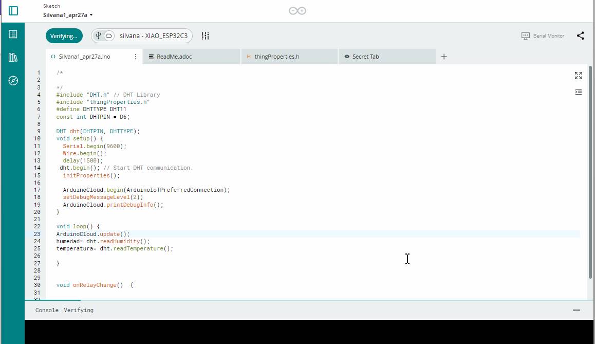
#include "thingProperties.h"
#include < LiquidCrystal_I2C.h>

LiquidCrystal_I2C lcd(0x27,20,4);  // set the LCD address to 0x27 for a 16 chars and 2 line display


void setup() {
  // Initialize serial and wait for port to open:
  Serial.begin(9600);
  // This delay gives the chance to wait for a Serial Monitor without blocking if none is found
  delay(1500);

  // Defined in thingProperties.h
  initProperties();

  // Connect to Arduino IoT Cloud
  ArduinoCloud.begin(ArduinoIoTPreferredConnection);
  setDebugMessageLevel(2);
  ArduinoCloud.printDebugInfo();

  lcd.int();                      // initialize the lcd
  lcd.backlight();
  lcd.setCursor(0,0);
  lcd.print("Hola Silvana :D :");
}

void loop() {
  ArduinoCloud.update();
  // Your code here


}

void onMensajeSilvChange()  {
  // Add your code here to act upon MensajeSilv change
  lcd.setCursor(0,1);
  lcd.print(mensaje_silv);
  delay(500);
}
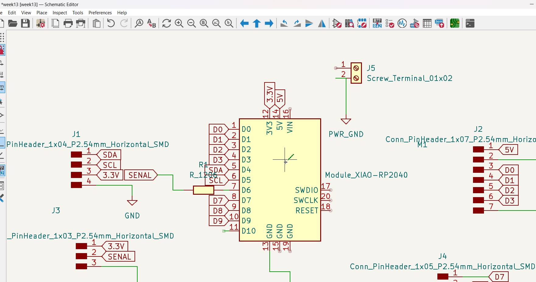
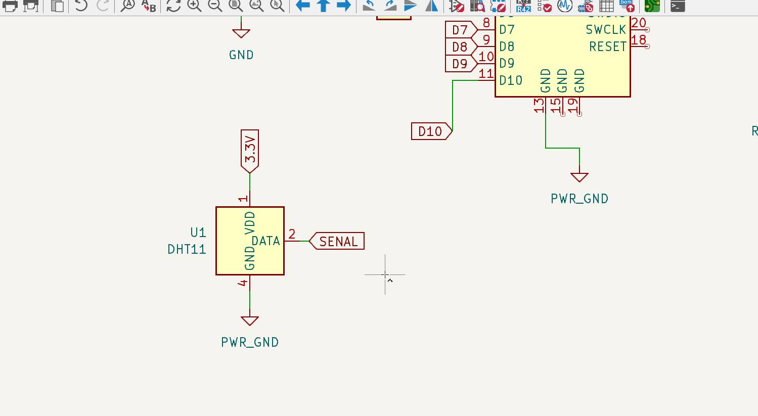
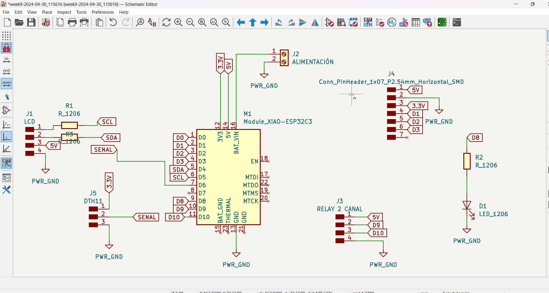
I am making the DTH11 pins, taking into account the 3.3V power and signal pins
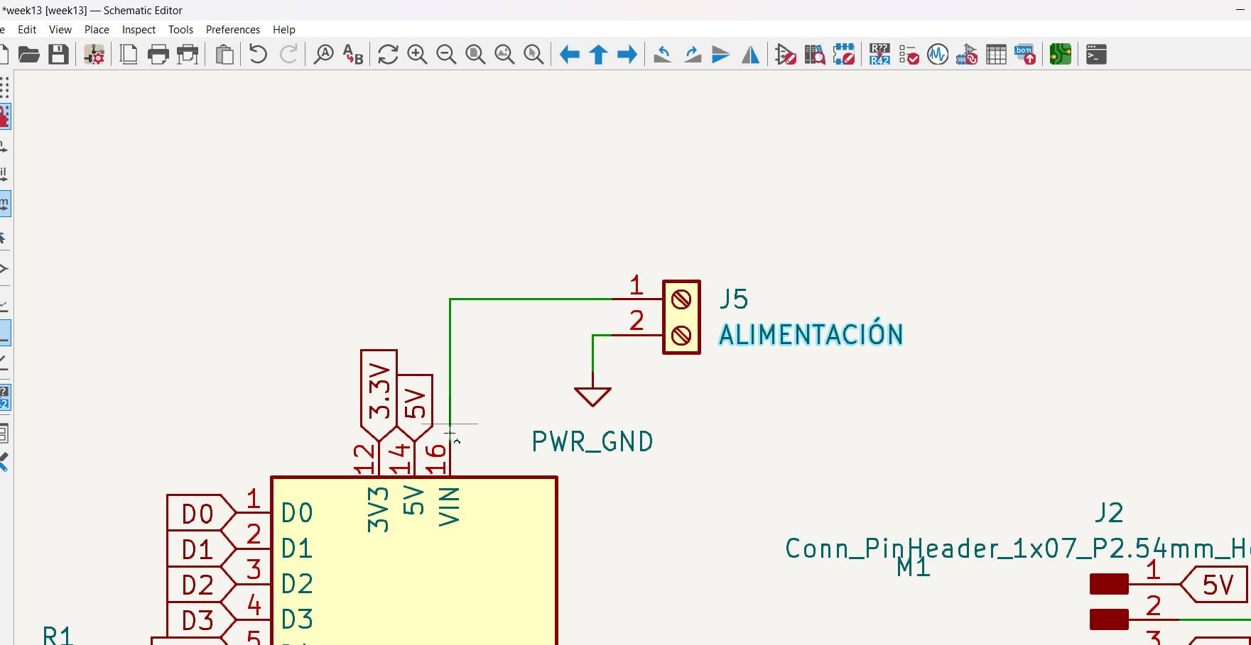
Here I placed an input to feed my board.
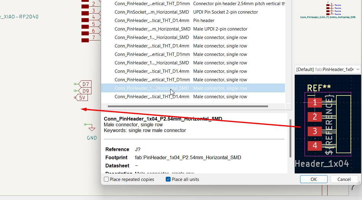
Here add a 4 pin to add other outputs
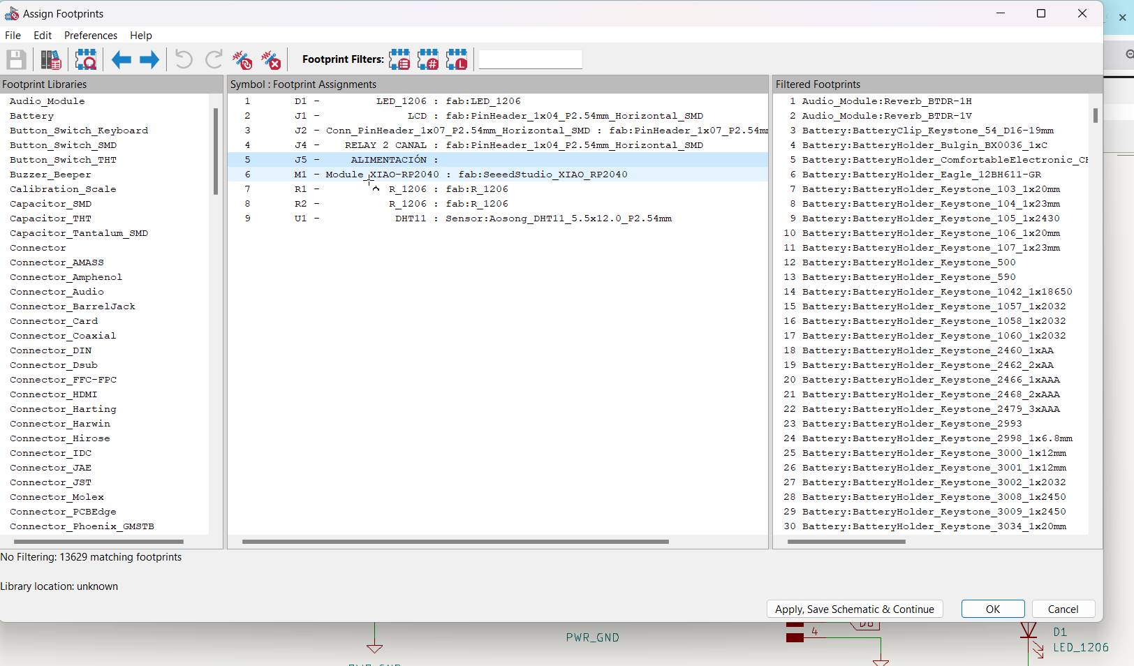
Here I see the list of components that I am using.
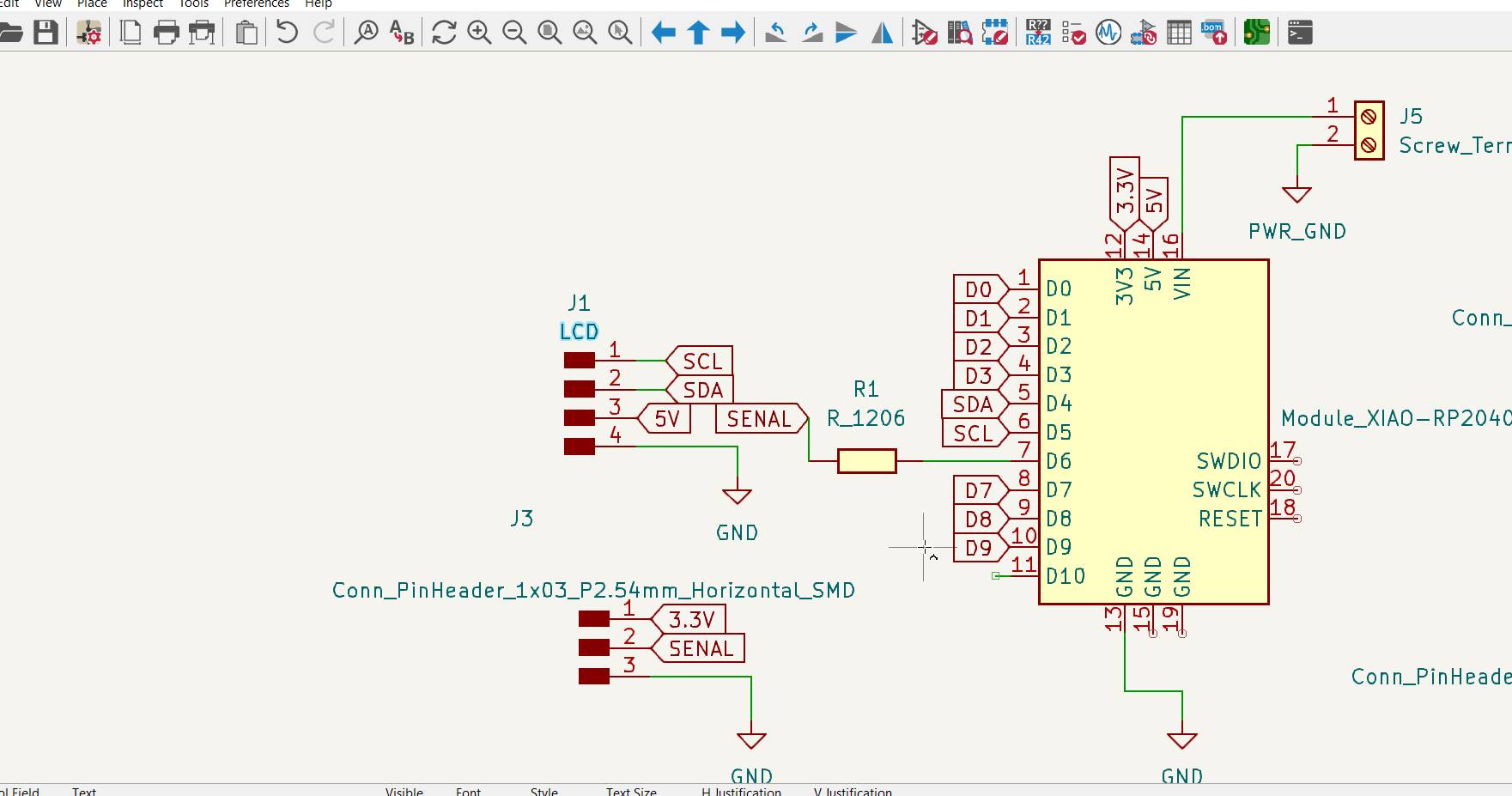
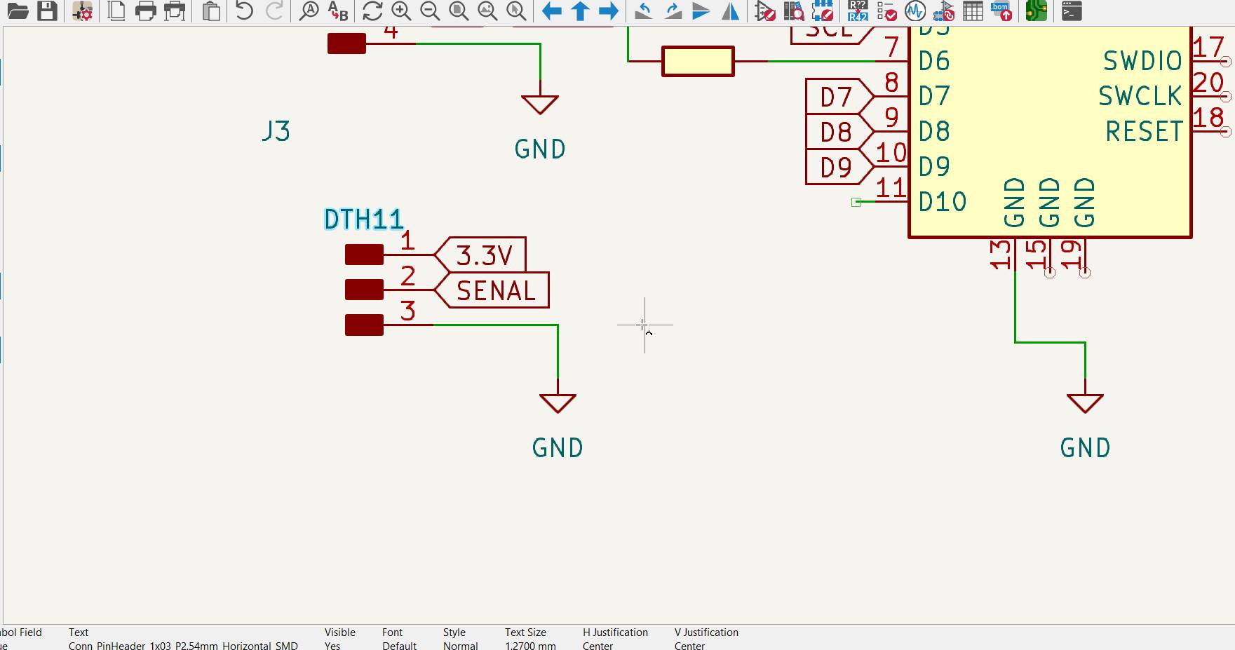
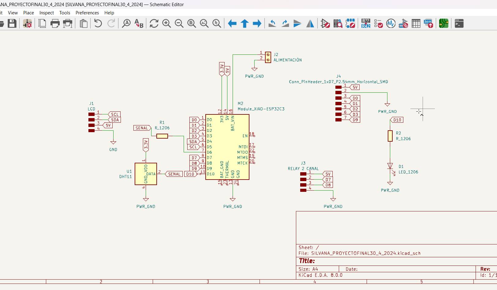
an overview of how my scheme is going
General view diagram
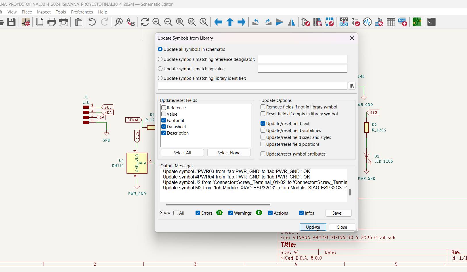
We load the symbol
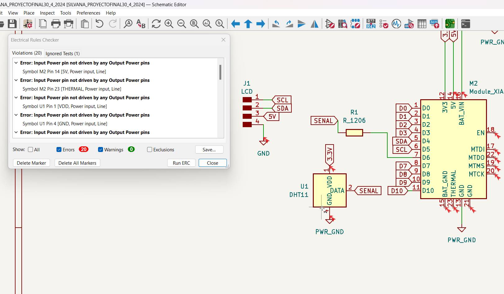
We see connection errors or that something is not connected correctly or is not connected.
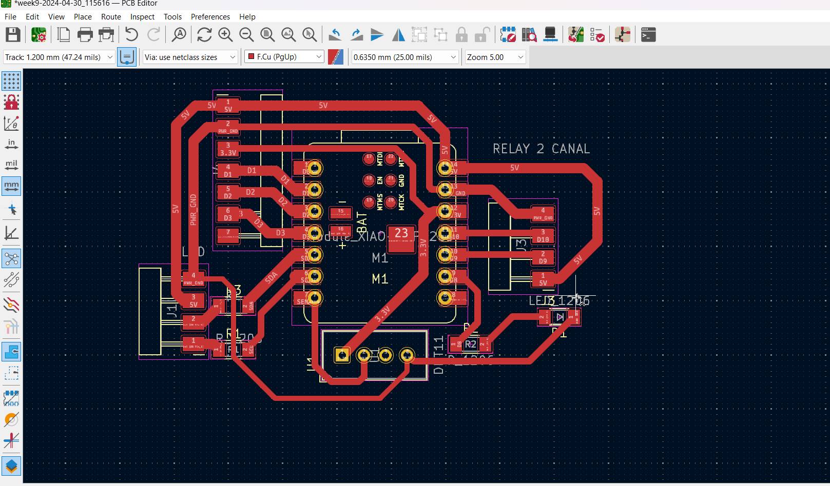
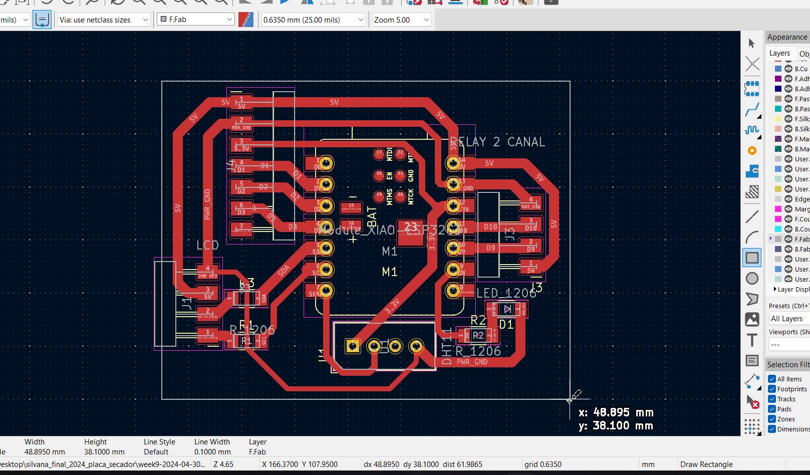
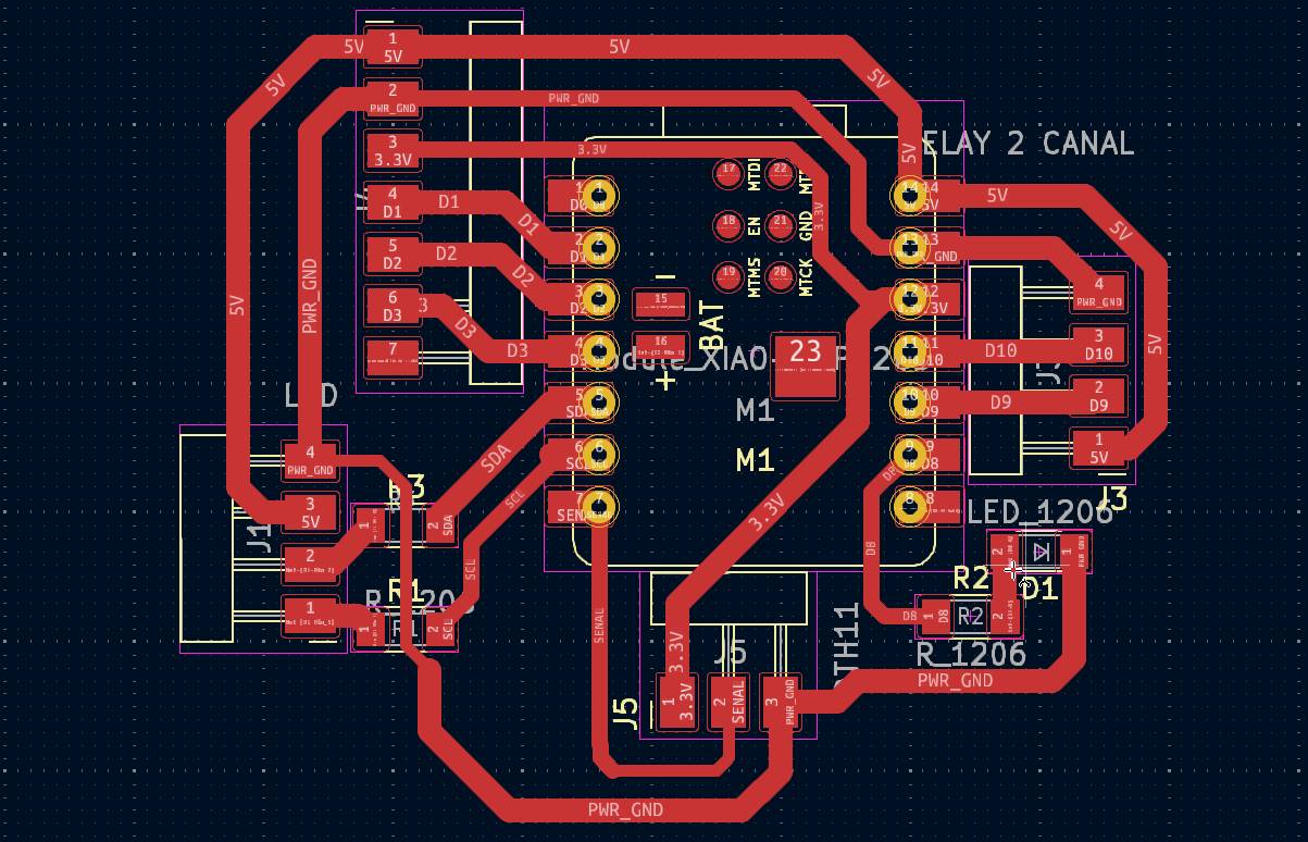
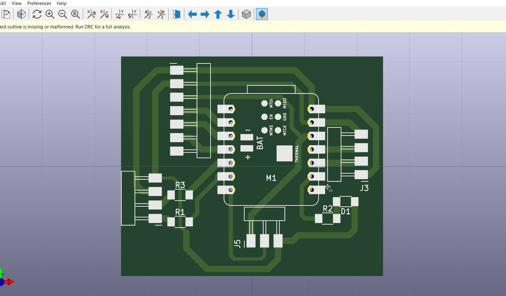
Final result
Here in 3D plan of how the tracks would go
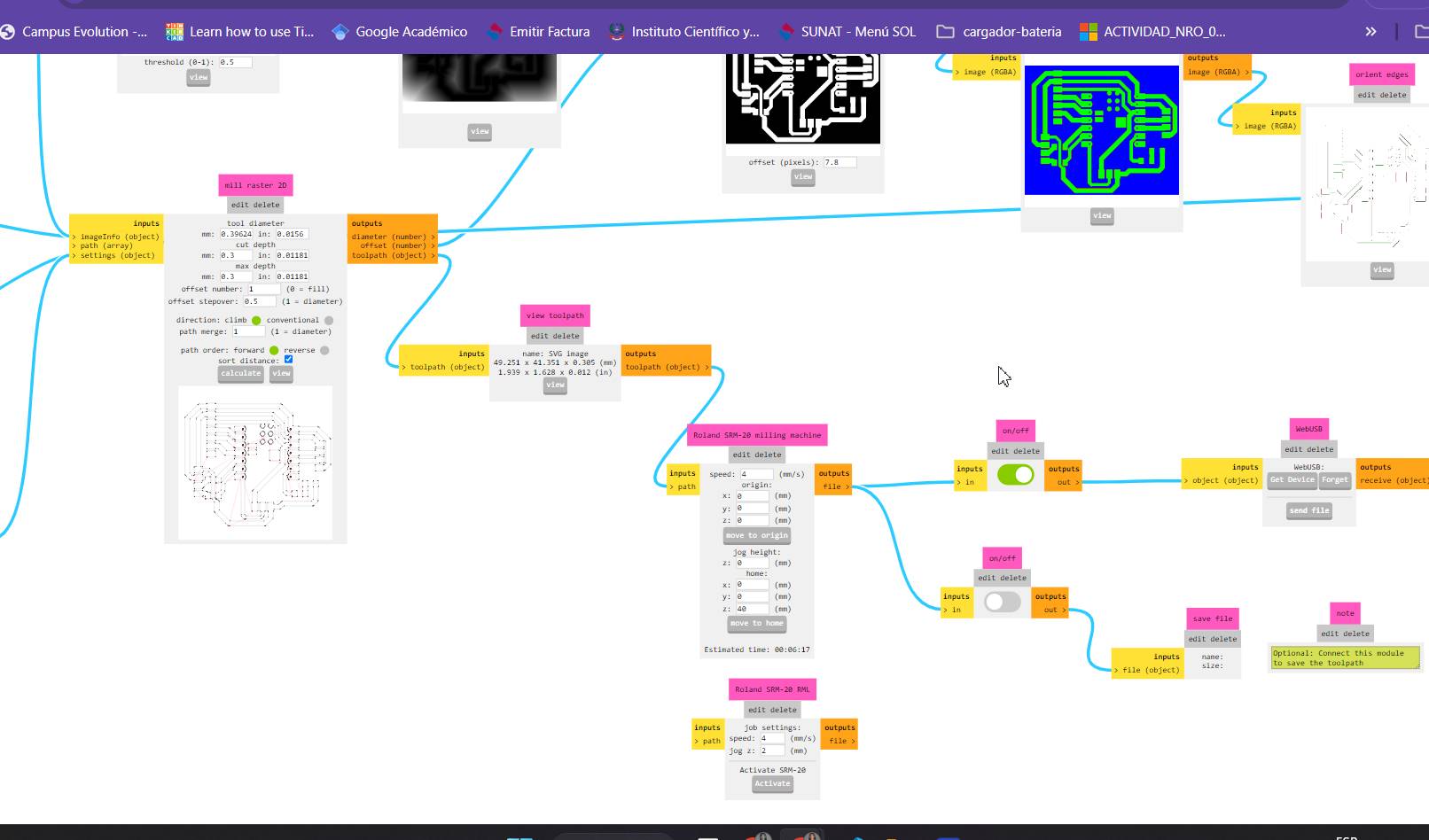
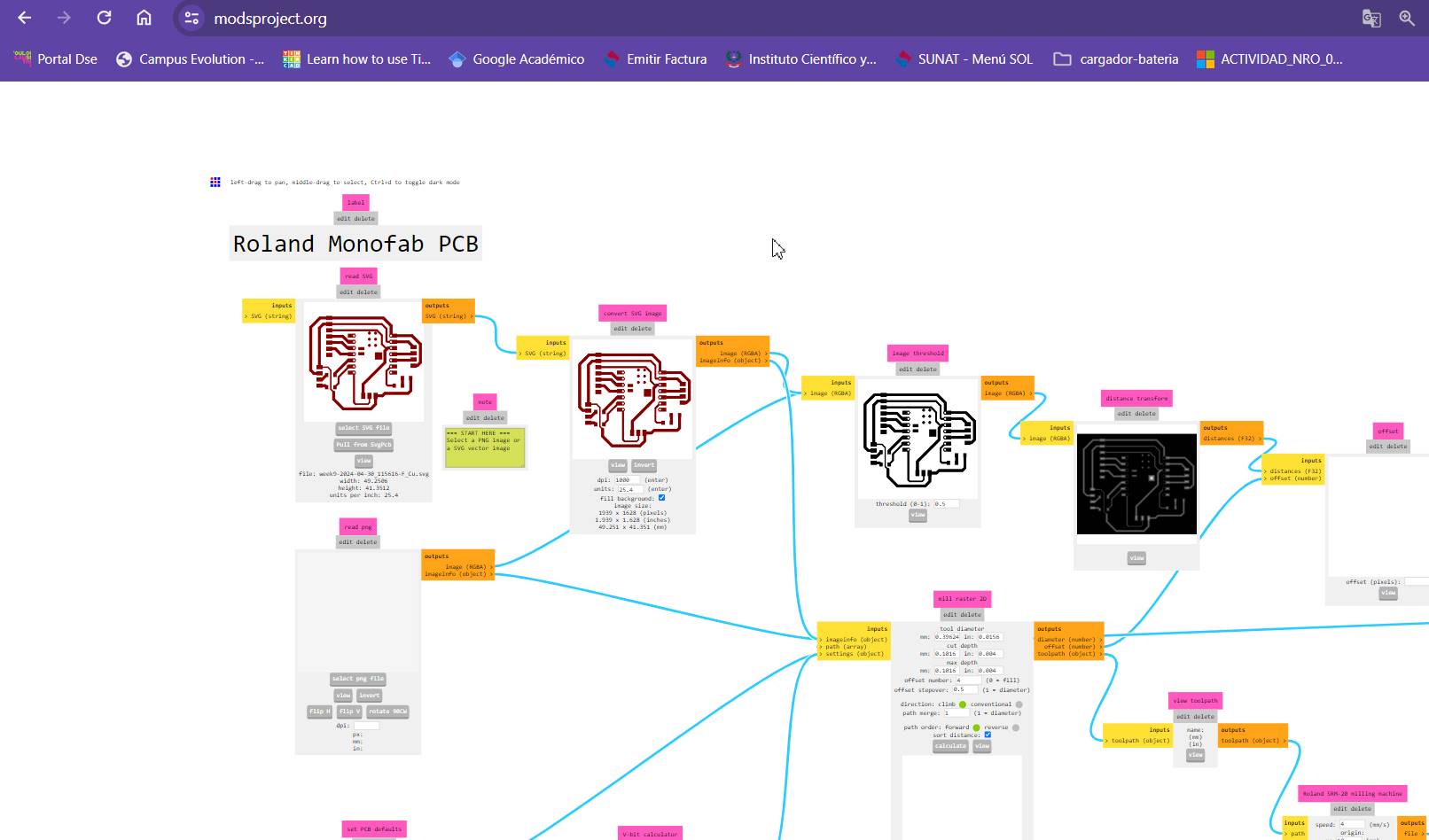
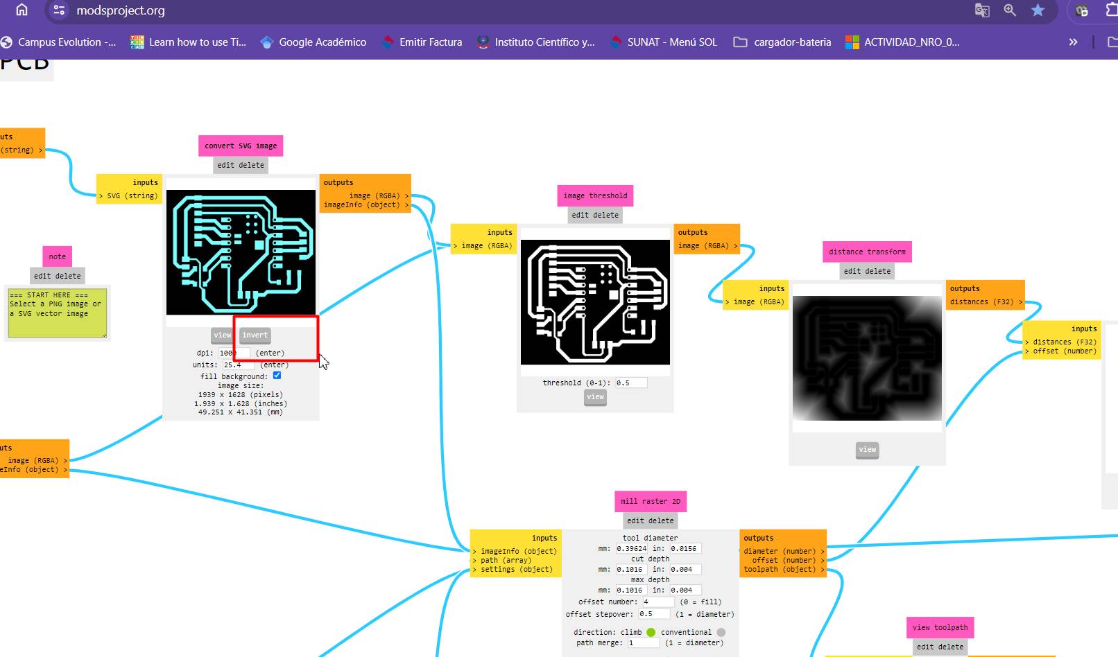
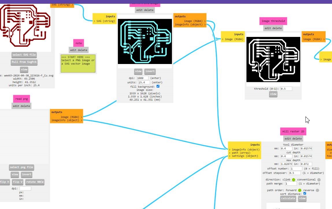
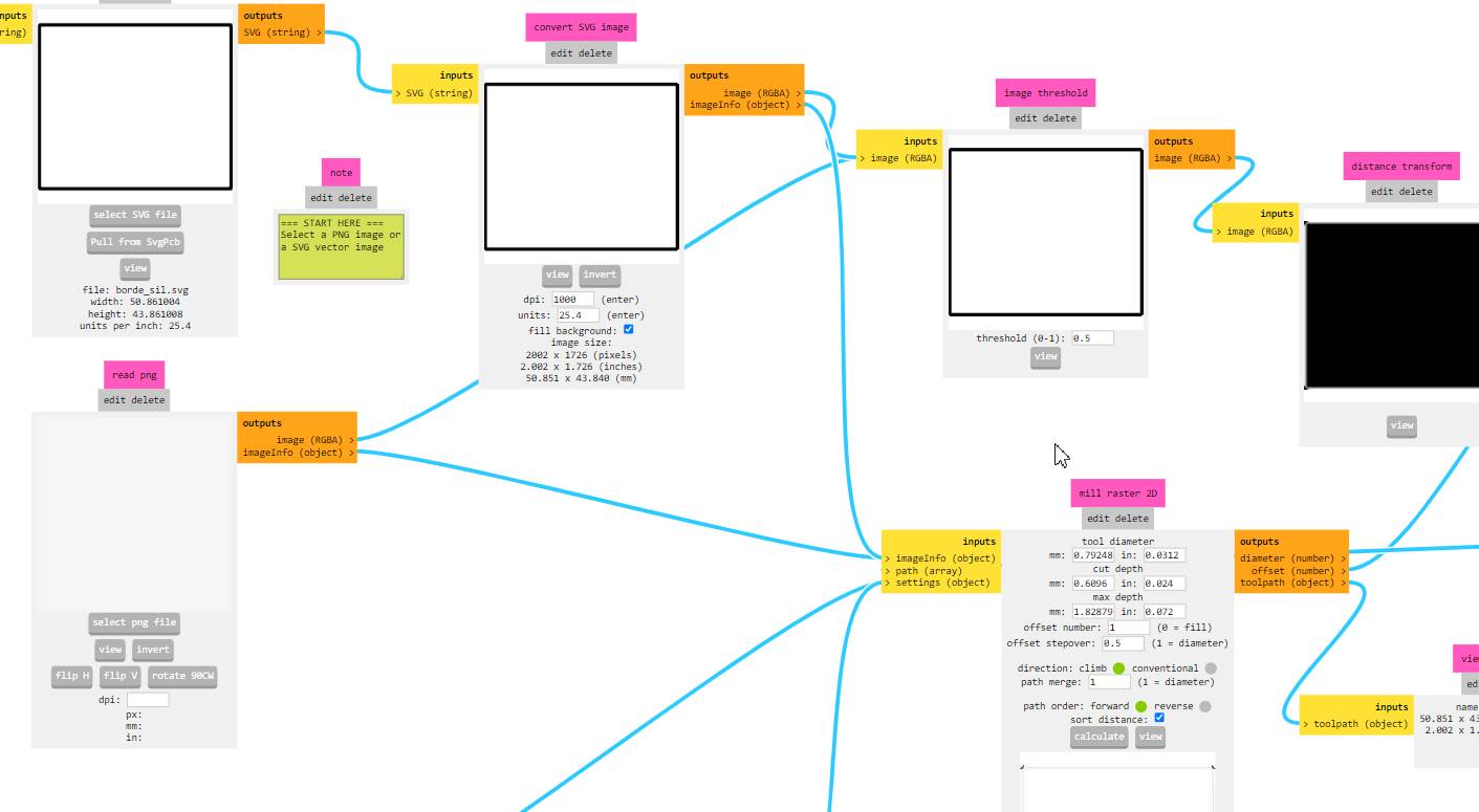
Now we go to the mods to be able to enter SVG
Here it is placed in red, depending on what you export from kicad
I reversed it so that it is black and the tracks come out well.
We can see it in black and white now.
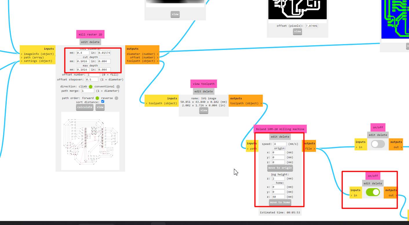
Now I changed the values to be able to mill, only everything went wrong, so I did it again.
Lines of my board
The edge of my end plate will be rectangular
Milling & Soldering the Board
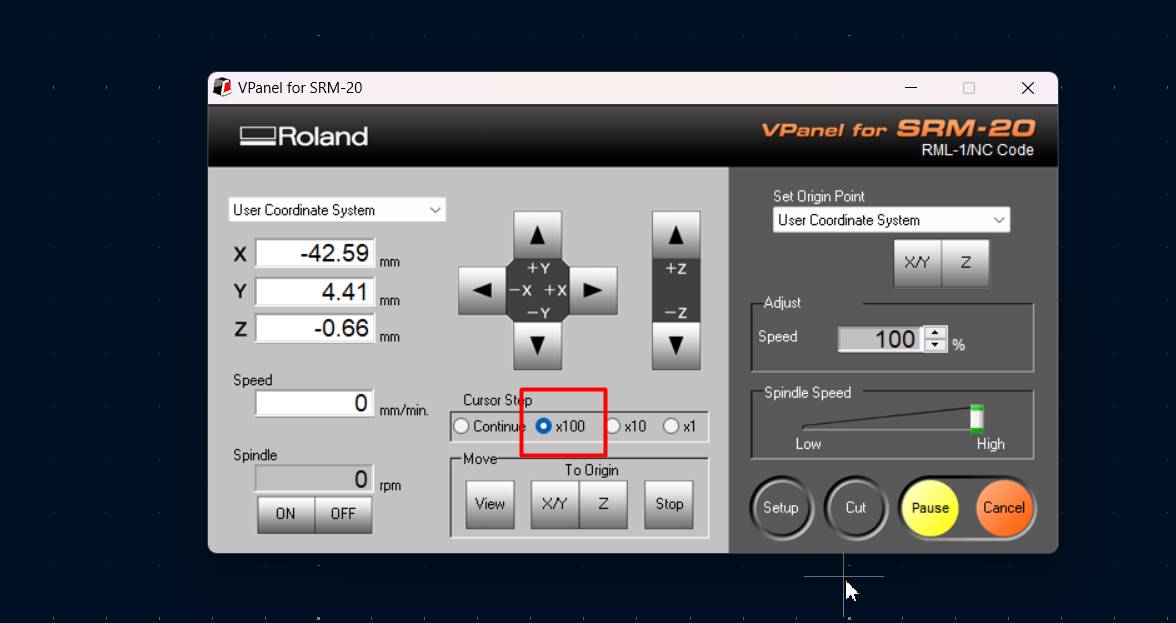
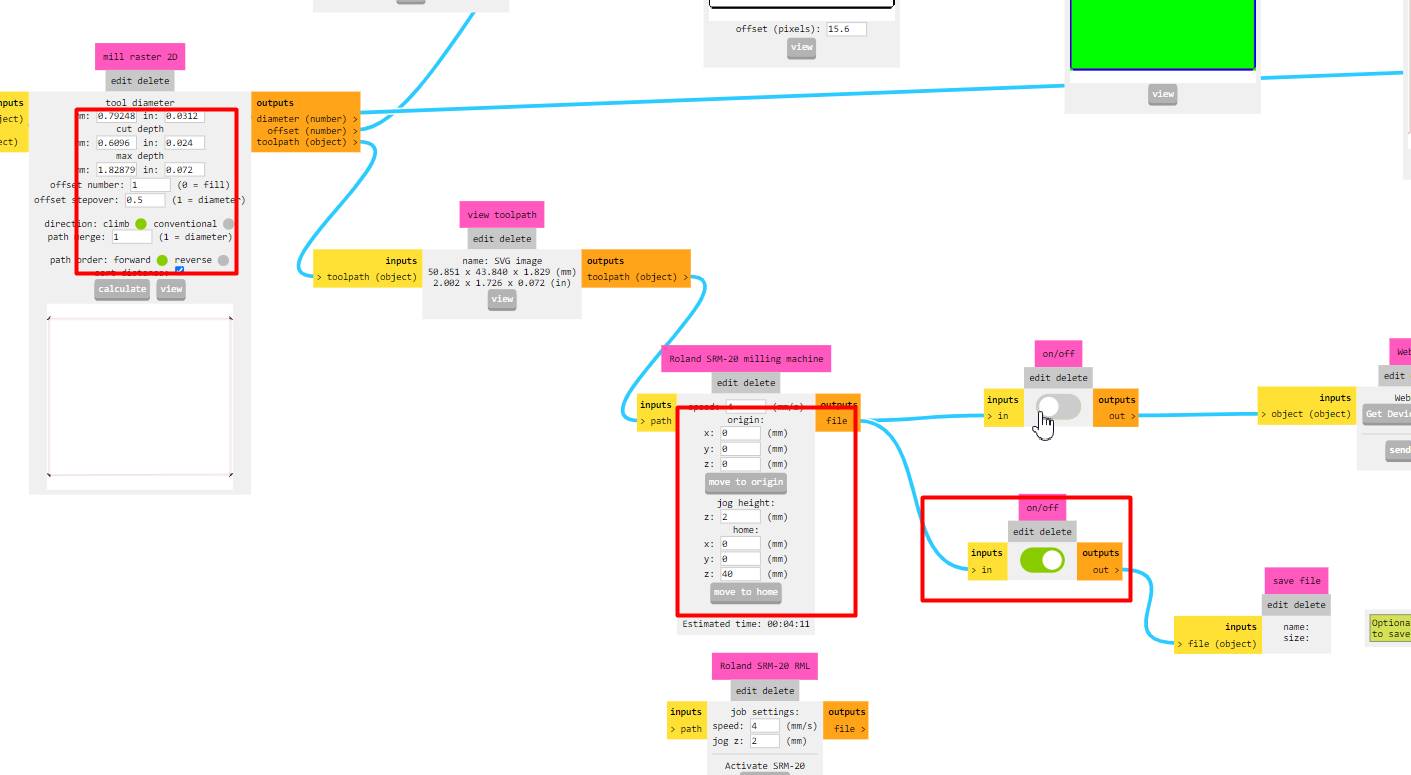
Here I am placing the point of origin with which I will start the machine
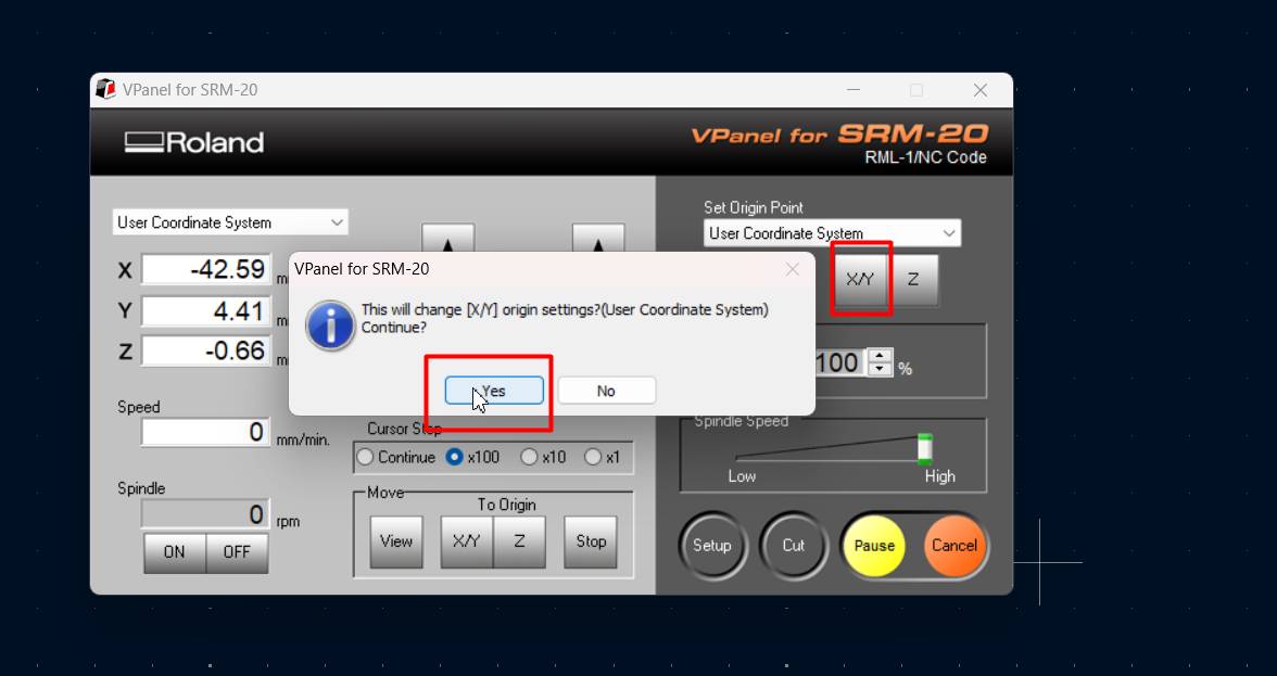
Here I am placing the new coordinates of origin, I understand more and more how to use it.
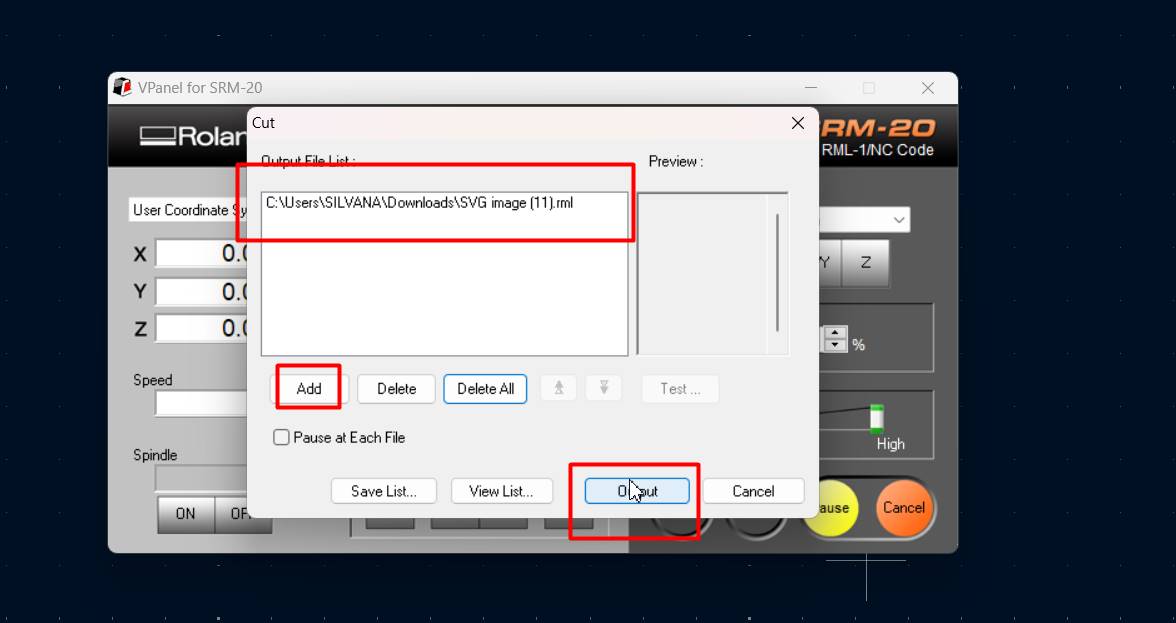
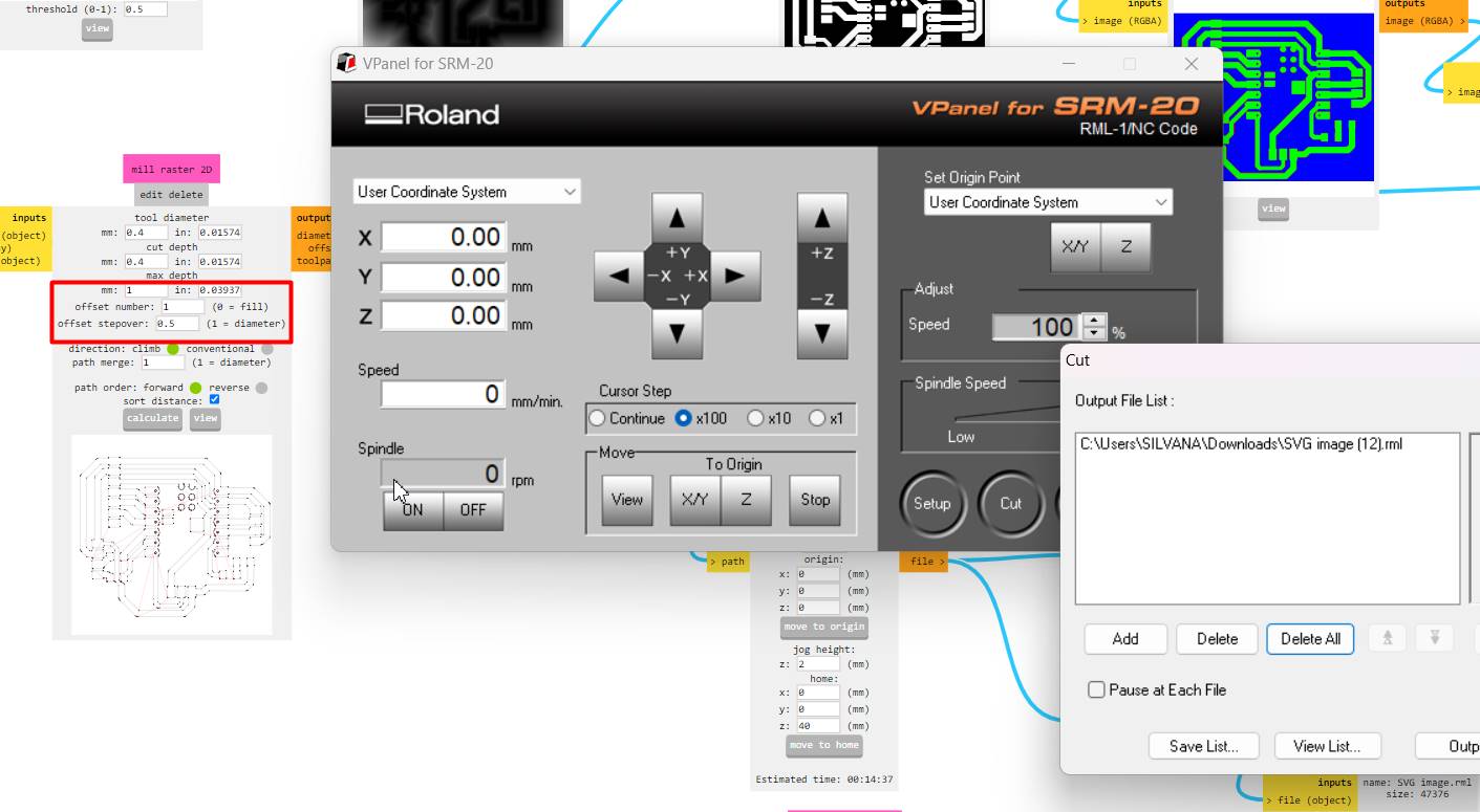
Now I download the .rml file, place ADD and give it Output
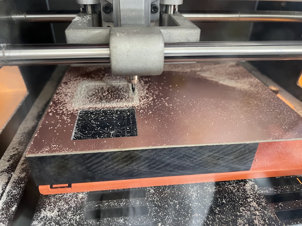
After carefully reviewing the values I entered, guess what was very deep and my first test was ruined, I wanted to cry because I only had that piece of plate left T_T
Here set the slice and then the origin point to 0 and just the home on the Z axis to 40mm remember that so it doesn't scratch your plate.
Now I changed the values to be able to mill, only everything went wrong, so I did it again.
This is the successful result I had for my board, later I will show you my mistake.
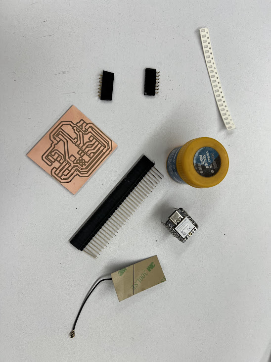
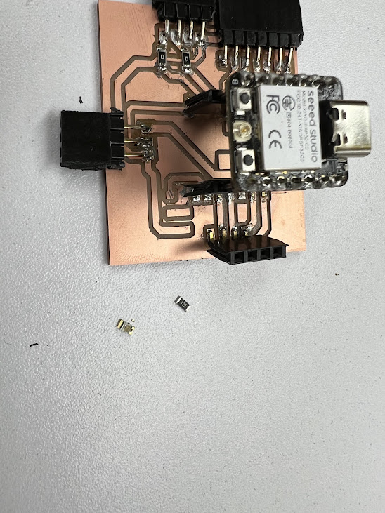
Here I gathered everything I was going to need, and you know that it was very useful for soldering, the soldering paste, which is very difficult to get in Peru.
beautiful soldering, here I almost forgot to tell you that I also have the resistors and the LEDs ready to place it, as I told you, super easy to place with the paste.
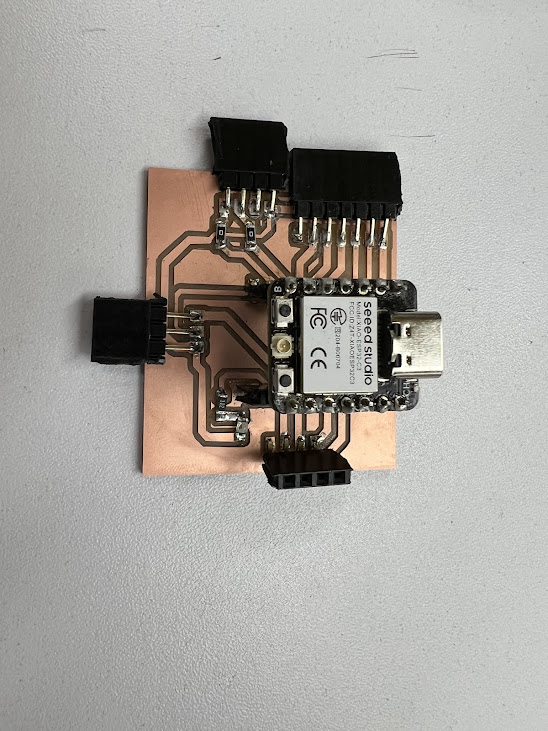
Final result of my welding, shiny
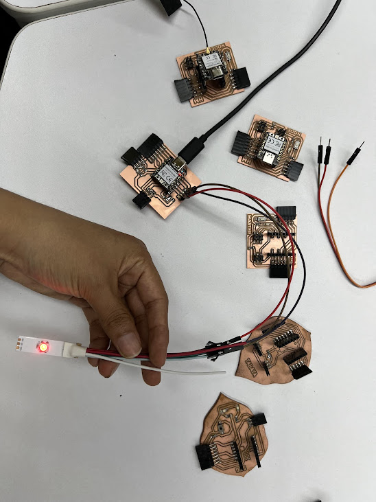
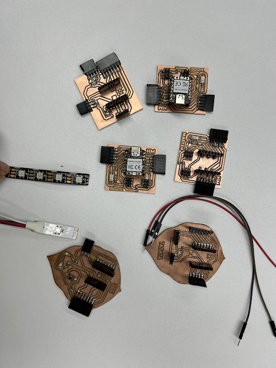
Gathering the things we were going to need for our connection, we can see Hans' plates on which he became slaves and a master.
My board would be a slave, and Hans's board would be the master, our first test will be wired.
CABLE COMMUNICATION Group activity
Programming
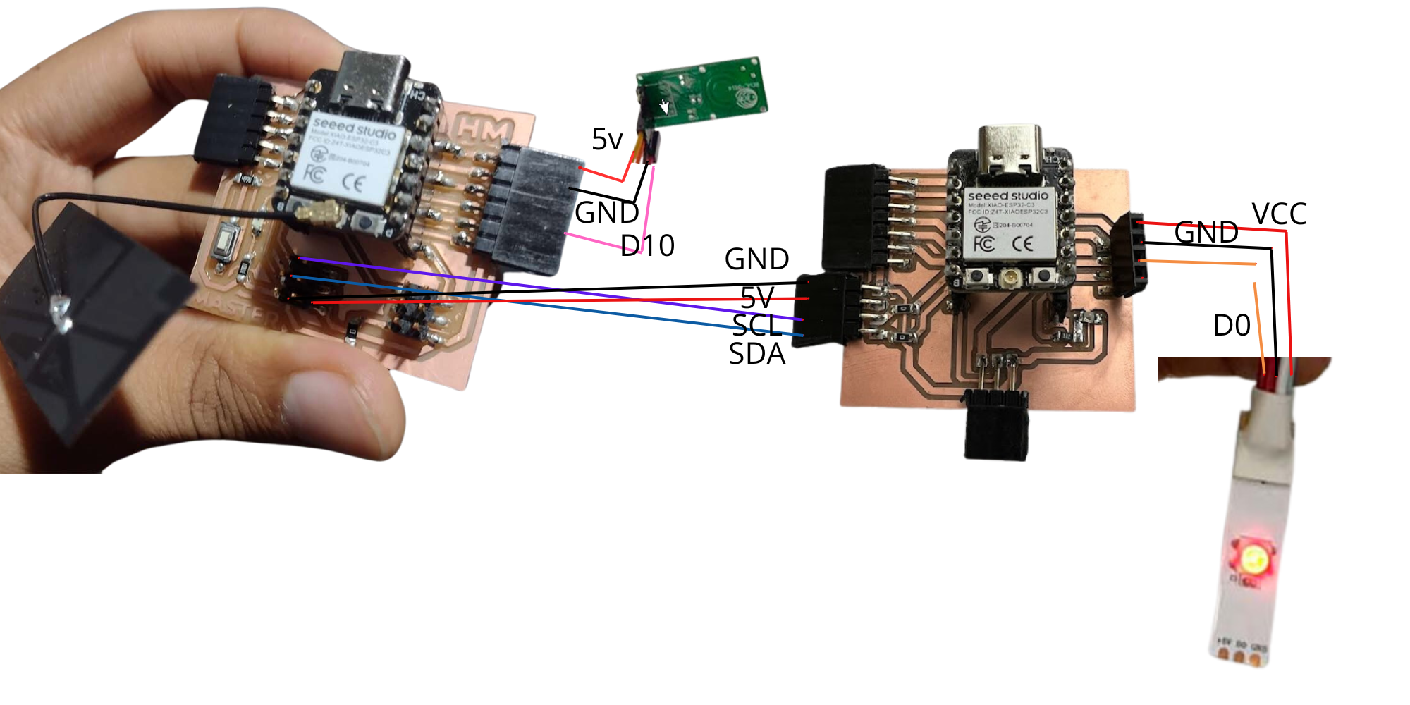
We made a connection in I2C communication so that both can work via cables. The XIAO RP2040 C3 was used on my board and a XIAO ESP32 was used on Hans' board.
I will show you the programming on each board, first Hans's and then mine.
HANS BOARD
	#include Wire.h

	const int sensorPin = D10; // PIN OF XIAO ESP32 C3

	void setup() {
	  Wire.begin(); // Start I2C communication
	  pinMode(sensorPin, INPUT);
	}

	void loop() {
	  int sensorValue = digitalRead(sensorPin);
	  Wire.beginTransmission(9); // Slave address
	  Wire.write(sensorValue);
	  Wire.endTransmission();
	  delay(1000); // Wait for 1 second before reading the sensor again
	}
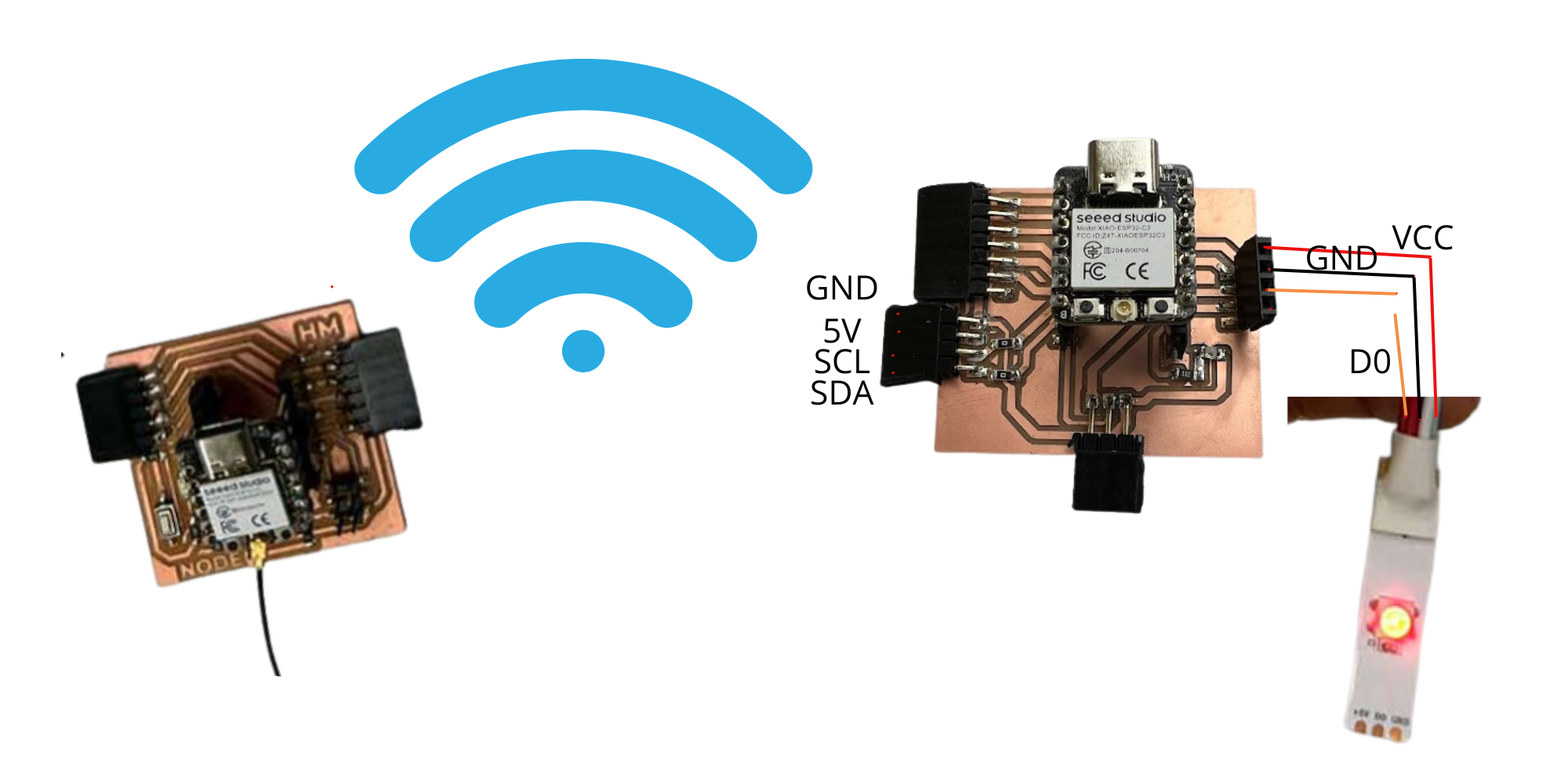
Connections of the 2 boards via WIFI, we recommend communicating between 2 XIAO ESP32 C3 microcontrollers, Hans' board was the editor and works as a switch and my board has a neopixel as an output.
To achieve communication we use MQTTX, where we must have a master (Hans board) and a slave (me), where I receive information from the master, process and perform the action that was programmed.
First we connect both boards to a different computer and begin to program it so that they have communication between them via MQTTX.
Hans Board
	#include WiFi.h
    #include PubSubClient.h

    const char* ssid = "YourSSID";
    const char* password = "YourPassword";
    const char* mqtt_server = "broker.emqx.io";

    const char* topic = "week13/wifi"; // Topic

    const int switchPin = D2; // Switch Pin

    WiFiClient espClient;
   PubSubClient client(espClient);

    int lastSwitchState = HIGH; // Previous switch state

    void setup() {
                        Serial.begin(115200);
                        pinMode(switchPin, INPUT_PULLUP);
                        setup_wifi();
                        client.setServer(mqtt_server, 1883);
                        }

                        void setup_wifi() {
                        delay(10);
                        Serial.println();
                        Serial.print("Connecting to ");
                        Serial.println(ssid);

                        WiFi.begin(ssid, password);

                        while (WiFi.status() != WL_CONNECTED) {
                        delay(500);
                        Serial.print(".");
                        }

                        Serial.println("");
                        Serial.println("WiFi connected");
                        Serial.println("IP Address: ");
                        Serial.println(WiFi.localIP());
                        }

                        void reconnect() {
                        while (!client.connected()) {
                        Serial.print("Connecting to MQTT server...");
                        if (client.connect("switchClient")) {
                        Serial.println("Connected");
                        } else {
                        Serial.print("failed, rc=");
                        Serial.print(client.state());
                        Serial.println(" trying again in 5 seconds");
                        delay(5000);
                        }
                        }
                        }

             void loop() {
                        if (!client.connected()) {
                        reconnect();
                        }
                        client.loop();

                        int switchState = digitalRead(switchPin);
                        if (switchState != lastSwitchState) { // If there's a change in switch state
                        if (switchState == LOW) {
                        client.publish(topic, "a");
                        Serial.println("Switch pressed");
                        } else {
                        client.publish(topic, "b");
                        Serial.println("Switch released");
                        }
                        lastSwitchState = switchState;
                        }

                        delay(100); // Small delay to avoid switch bounce
                        }
By connecting the Arduino XIAO to the Arduino Cloud, you can access and control your device from anywhere with Internet access. This gives you the flexibility to monitor and manage your projects from any location.
Arduino Cloud offers an easy-to-use interface to monitor and control connected devices. This makes it more accessible to beginners or people without advanced programming experience. I really think you can use it if it's your first time making these connections.
With Arduino Cloud, you can program automated rules and actions for your devices. This allows you to create more sophisticated systems and automate specific tasks based on predefined conditions.
MQTTX provides an intuitive user interface that makes publishing easy
MQTTX is a powerful and versatile tool for remote communication and control of devices via the MQTT protocol.