Electronics Production
Let's cut!
Producing plates to understand how they are made
Let's cut!

Producing plates to understand how they are made
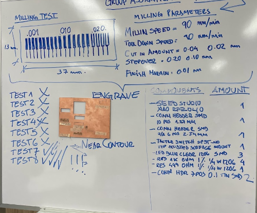
Our tasks for this week are:
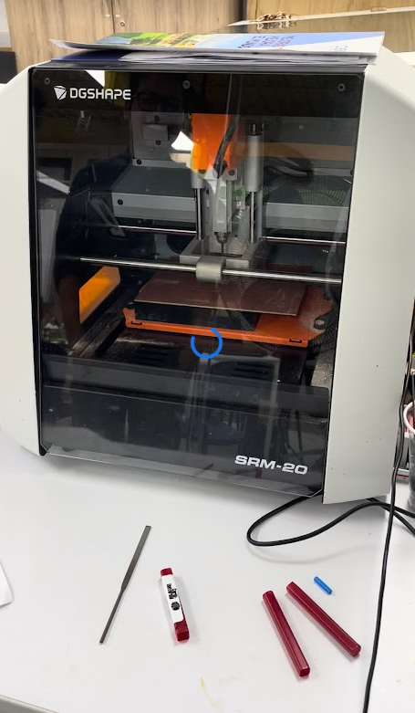
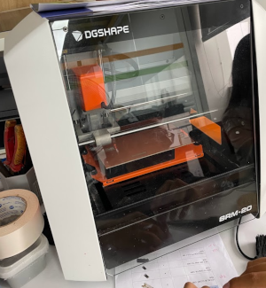
The machine I use is the monoFab SRM-20 from the Fab Lab of the Southern Scientific University.
MonoFab SRM-20
Seeed XIAO RP2040
PCB manufacturing with MonoFab - SRM-20
This week we were very united to do our homework for the week, I love my team.
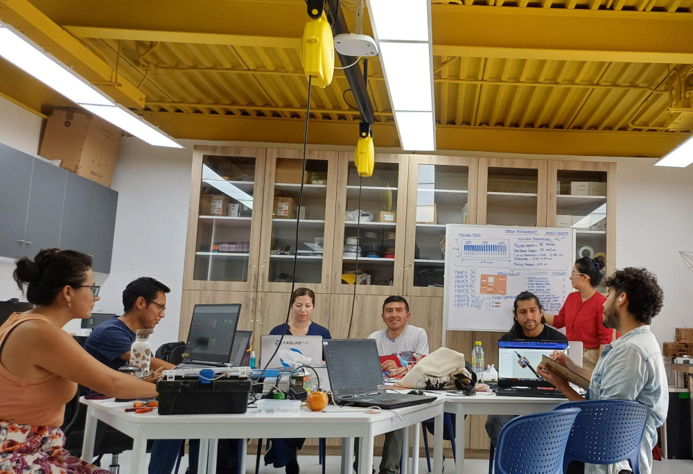
A week before my partners and I were looking for the electronic components because we knew that in Peru they did not sell everything complete, then with the help of Vanessa we managed to get the Xiao, with the help of the Fab Lab of Universidad Cientifica del Sur, we were able to make the boards and solder everything in the week.
Let's see what we all have to move forward together
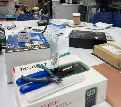
| item | Description | Price |
|---|---|---|
| One | CONECTOR HEADER SMD 10POS 1.27MM | Conector macho 2x2 | 3 PEN |
| Two | CONECTOR HEADER SMD R/A 6POS 2.54MM . | 2 PEN |
| Three | Tactile Switch SPST-NO Top Actuated Surface Mount | 2 PEN |
| Four | SEEED STUDIO XIAO RP2040 | 6 PEN |
| Five | LED BLUE CLEAR 1206 SMD | LED SMD | 3 PEN |
| 16 PEN | ||
We used the 1/64 and 1/32 milling cutters that were very important in the manufacturing process. Here you have a picture of each of them, you must be careful when calibrating because you can break, also remember that when calibrating have an hour to leave a space between the cutter and the base, then remove the hour and lower x100, another way is to put the cutter a little more to the bottom, and then lower and release the cutter in the short space you have between the base and the entrance of the milling cutter, and adjust about a half inch.
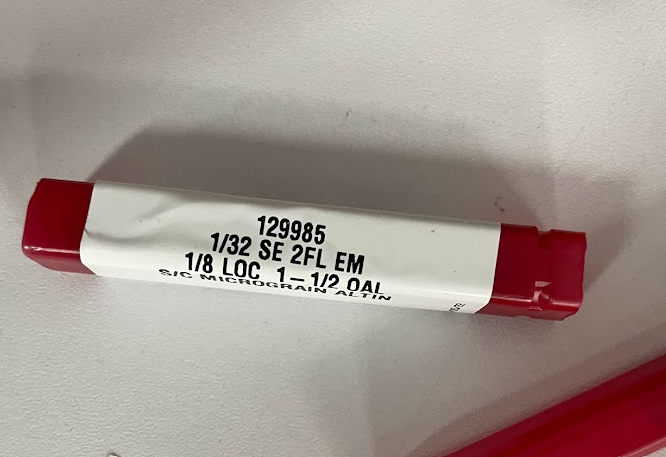
The 1/32 milling cutter (also expressed as 0.03125 inch or approximately 0.79 mm) is a tool commonly used in the development of electronic boards using the PCB (Printed Circuit Board) milling process.
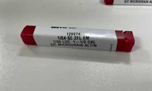
A 1/64 milling cutter (also expressed as 0.015625 inch or approximately 0.3969 mm) is an even finer tool than the 1/32 milling cutter. Its smaller size allows for more detailed cuts and finer traces in the PCB (Printed Circuit Board) milling process.
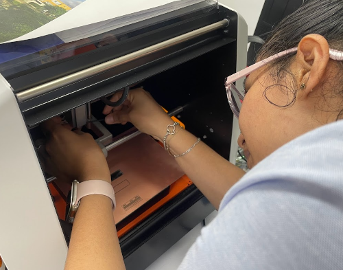
Calibration of a milling machine like the Roland monoFab SRM-20 is a critical process to ensure accurate and quality milling results.
let's start configuring together
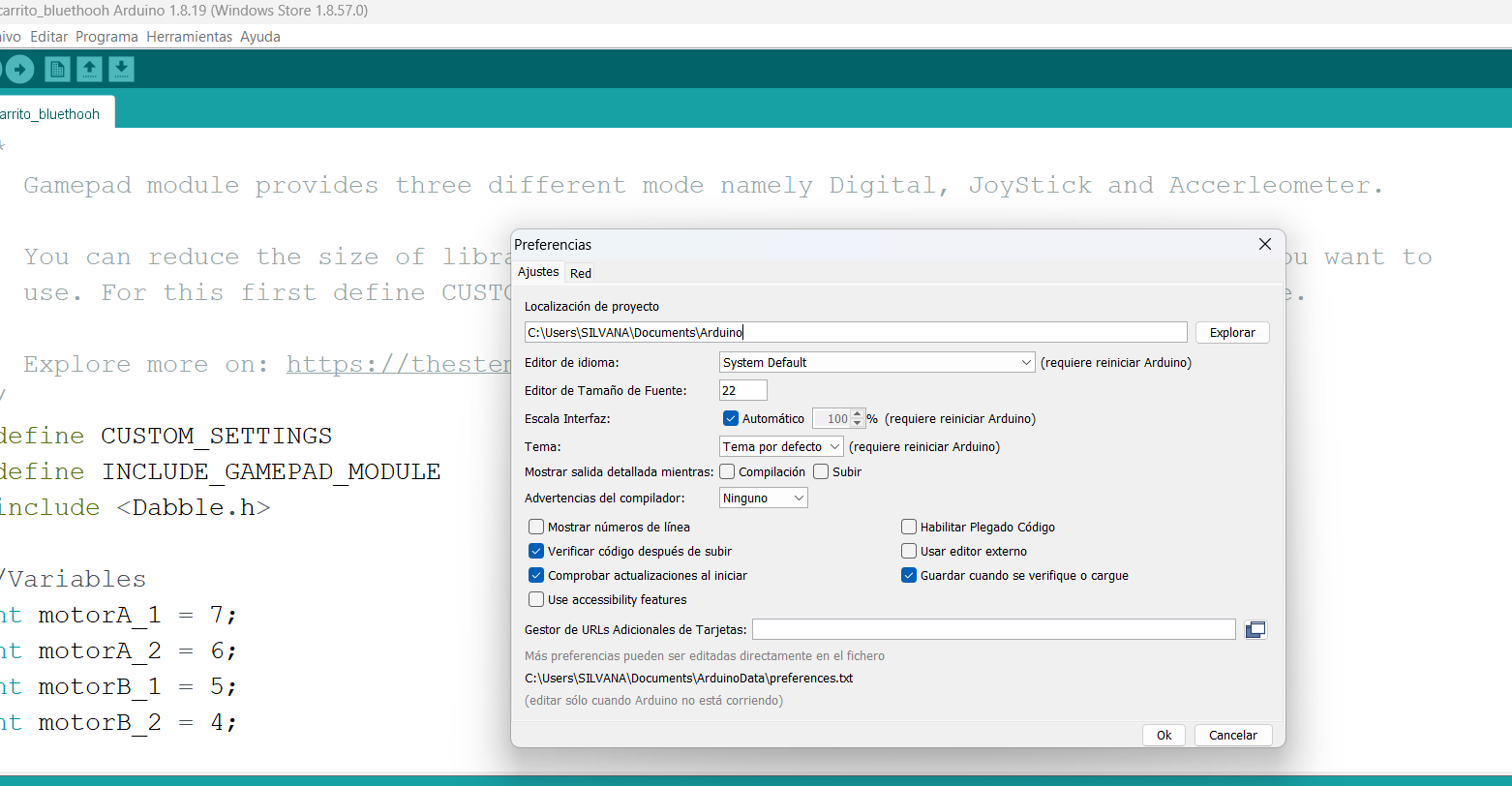
We review the documentation of Adrian Torres we see all the detail of the indications and the microcontorlador that he used to make the plate, we copy the links as indicated in the instructions, making sure that the links are placed correctly.
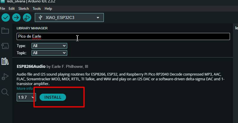
Here is to be able to place the board that we will use, in my case Esp 32 c3 Arduino-Pico de Earlephilhower .
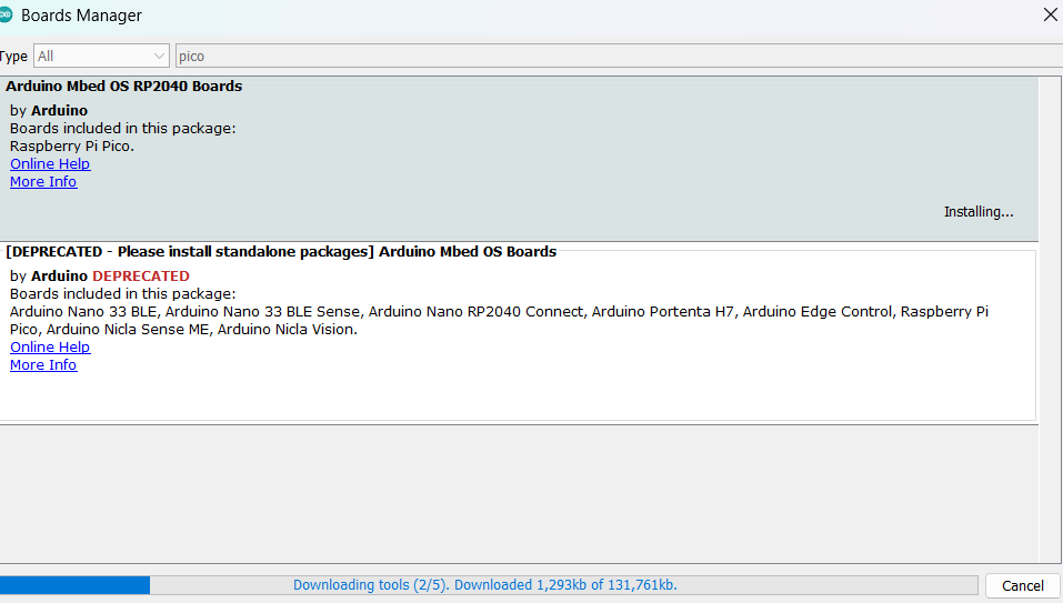
Here you can see another arduino update of what it looks like to install the Arduino mbed OS RP2040 Boards.
MODS CE (Community Edition) is a spin-off project of the CBA mods research project. MODS is a cross-platform modular tool for fablabs. It is based on independent but interrelated modules. MODS could potentially be used for CAD (computer-aided design), CAM (computer-aided manufacturing), machine control, automation, user interface creation, reading input devices, reacting to physical models and much more. The possibilities are virtually limitless. The goal of the community edition is to provide documentation, support and help the community to participate in the project and to encourage the development and exchange of new modules.
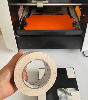
We place double contact tape on the board that we mentioned earlier so that we can glue the printed circuit board so that they cannot move when the work is being done and we can take care of our milling cutter.
For this first step we have to download the figure and pass it to the IMODELA CREATOR program, which is the program that we use before placing the configuration and the characteristics of the material that we will use.
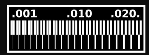
These are the parameters that worked for us, you have to test them, because each machine is different and it may not be the same configuration for you.
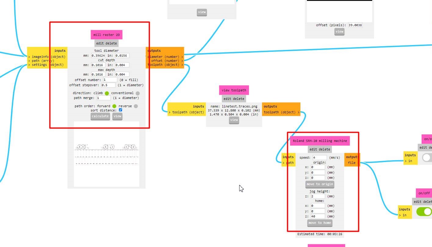
We start by making the plate for replication
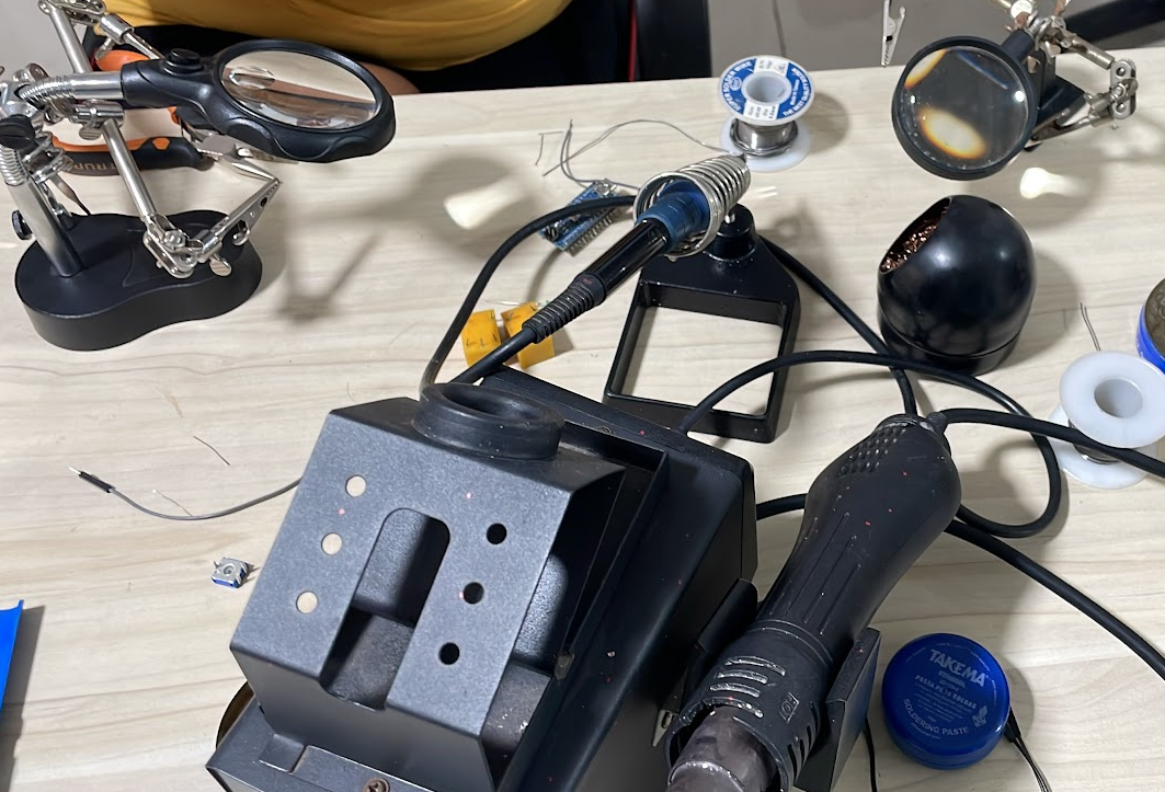

The first thing we did is to analyze the microcontroller we will use, we saw its information, we learned new terms and we saw its usefulness in several projects.
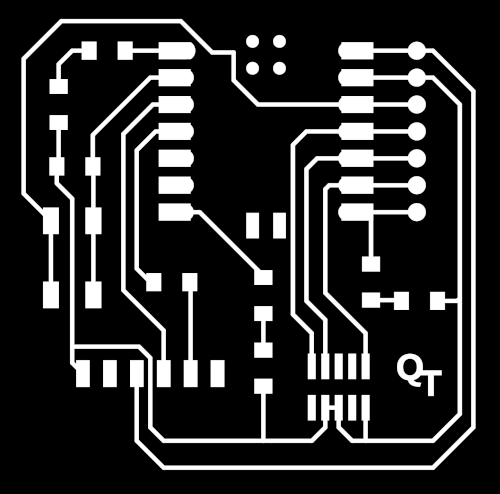
Here is the png file designed by Adrian torres, creator of this magnificent board with xiao
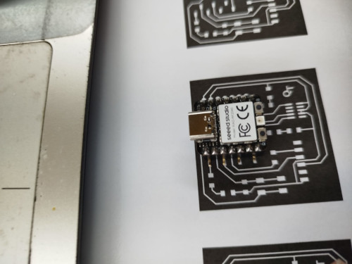
At the beginning I showed you how to get to this part, placing the png of the design of the plate you want to make, the important thing is the configuration of the mill rater 2D so that the tracks are well, reading several pages I saw that you should change the "offset number" to 1.

Here I show you the results without changing the values of the "offset number" calculate and you can see that the tracks are very thick
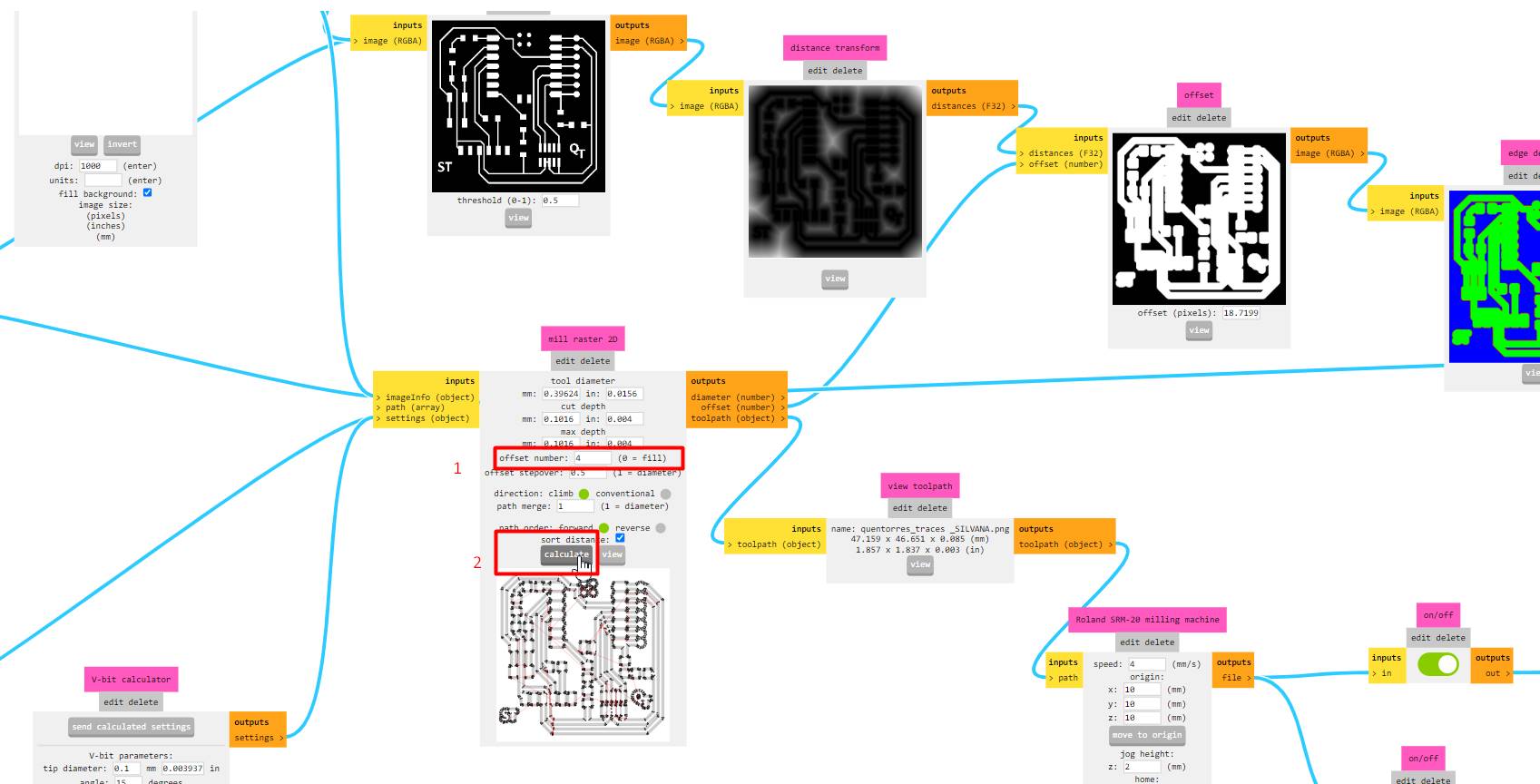
Here remember the test configuration.

The result

Here we can see the difference between the last tests, where we were able to achieve the objective we were asked to achieve for the group work. We understood the processes, configurations and we were able to obtain our board test...finally.

I started to let go, first I didn't have the correct tin to work with SMD, then my colleagues lent me one that worked well for me.
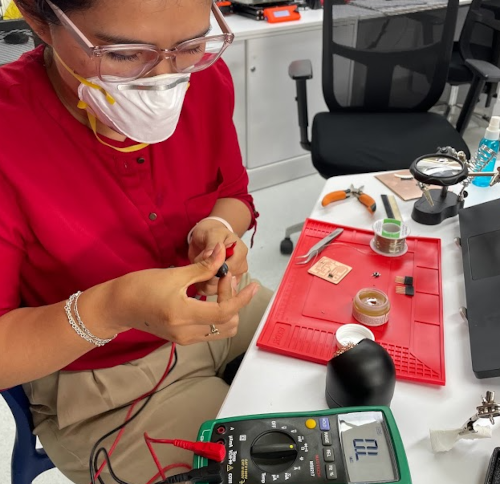
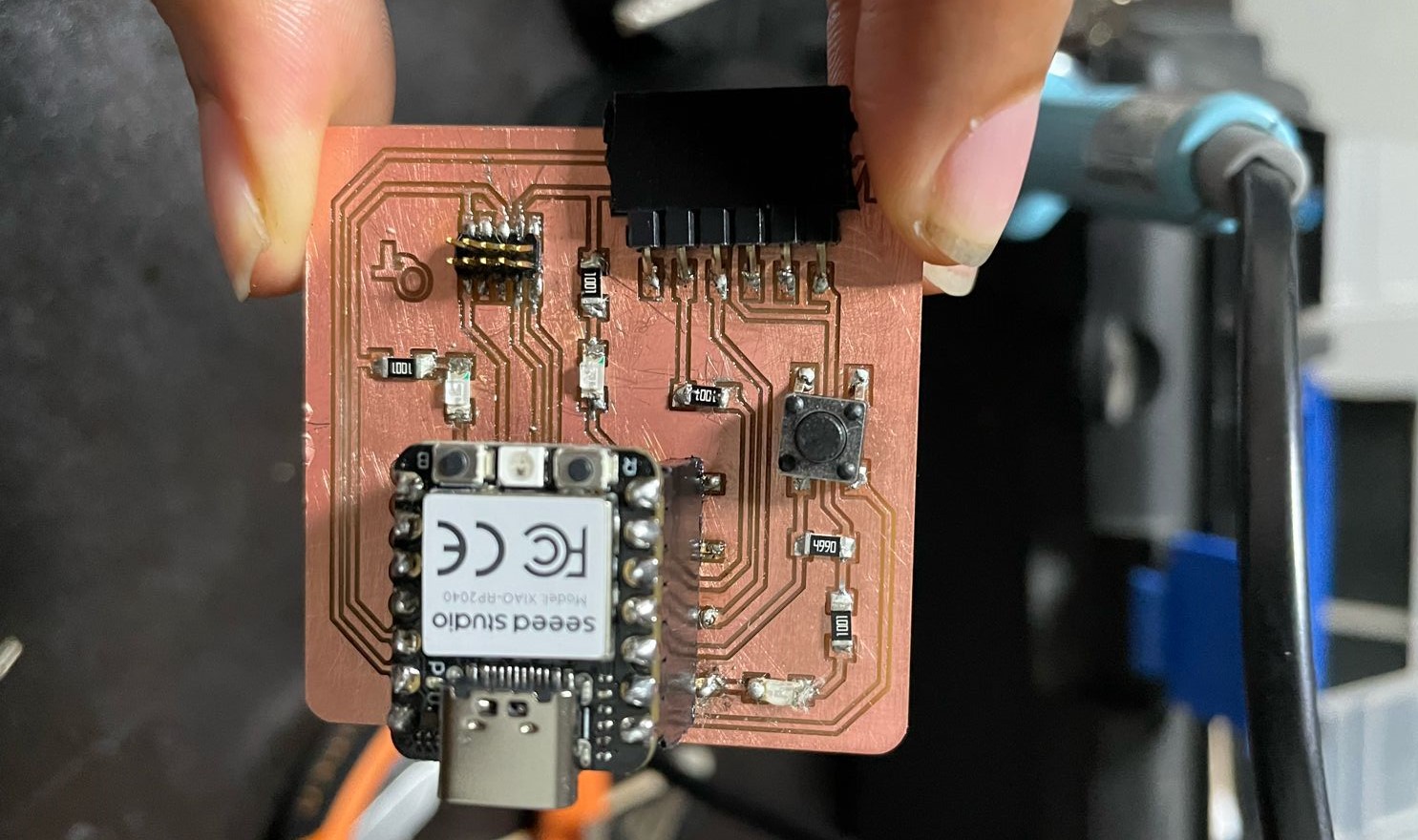
I wanted to put this picture, because it was just the moment when I finished soldering and it was already 1 am, I was very satisfied with the result of my plate.
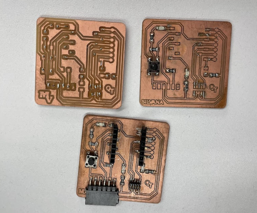
Actually there were many more attempts but these are the ones that best represent all that my colleagues and I lived, all soldering their board and between us seeing and recommending how it could be improved or how it would be easier to solder.