Electronic Production
Week 4
Group assignment:
- Characterize the design rules for your in-house PCB production process
Group 1
Group 2
Group 3
Group 1:
- Hans Moncca
- Maryori Vasquez
- Maria Angela Mejia
- Cristian Loayza
- Silvana Espinoza
- Jesus Lucero
- Renson Samaniego

Hans Moncca | Maryori vasquez
PCB PRODUCTION PROCESS
Before starting the assignments, my friend Maryori and me made a complete inventory of all the electrical components and tools we need for this week. Likewise, we also carry out an inventory to have everything in order and see what things we need to request it.
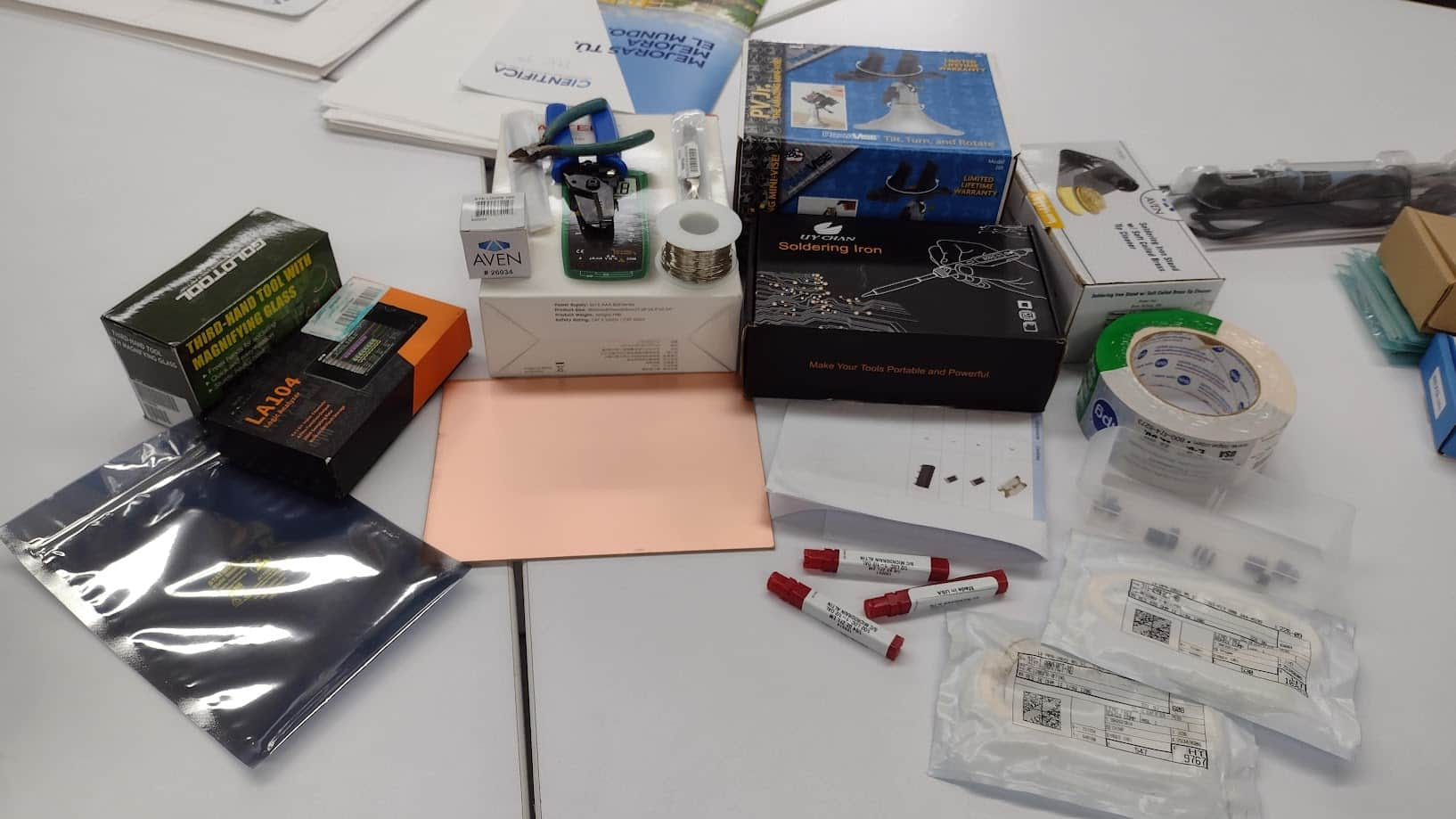
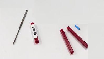
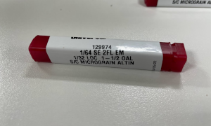
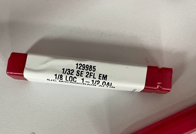
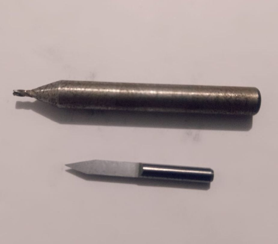
I could see that we have the 1/64 and 1/32 cutters that are going to be essential for this assignment. Here I leave a photograph of each of them.


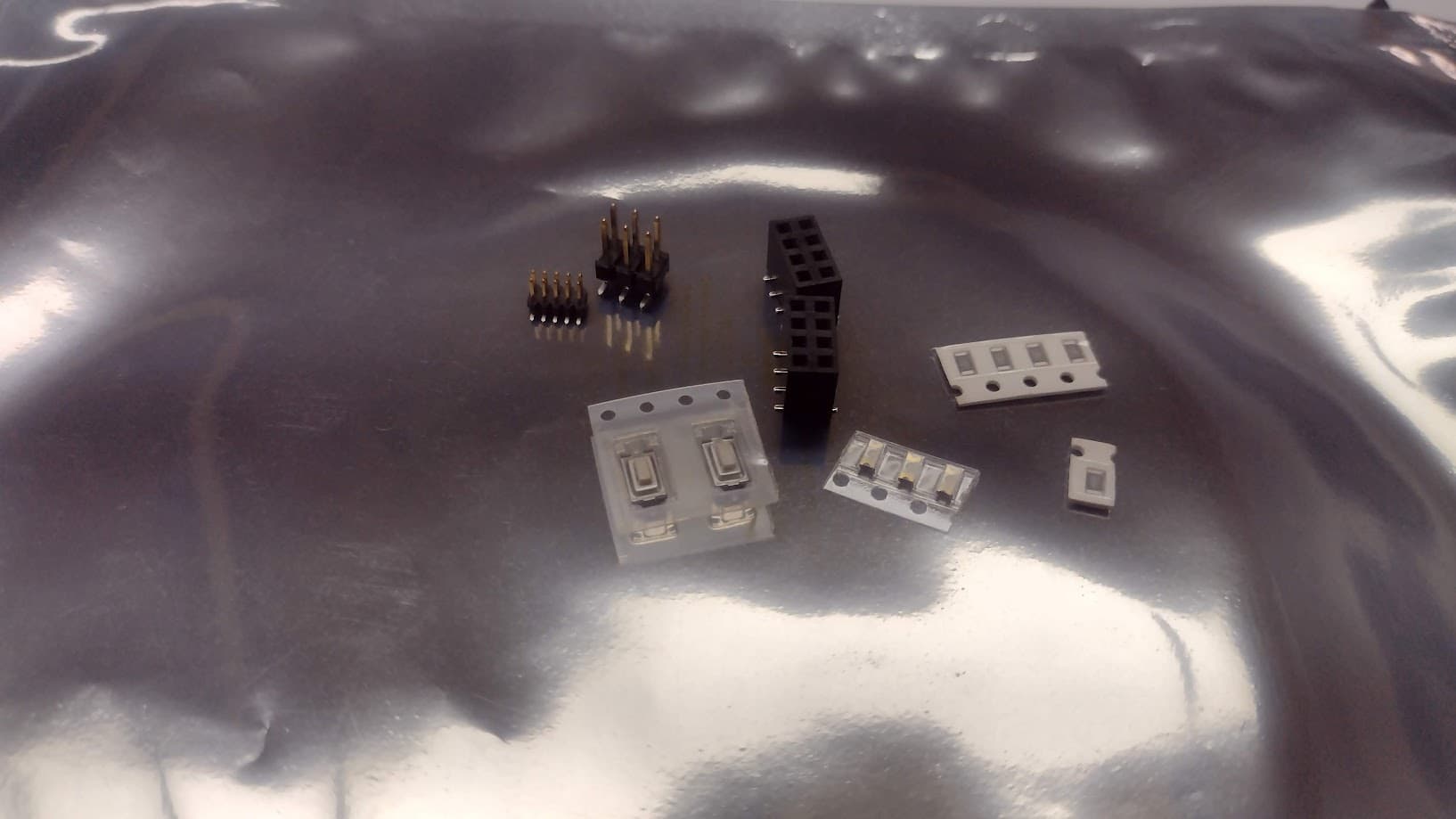
Finally, here is a photograph of the electronic components that we need to carry out the group and individual assignment.
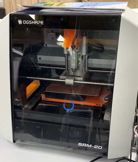
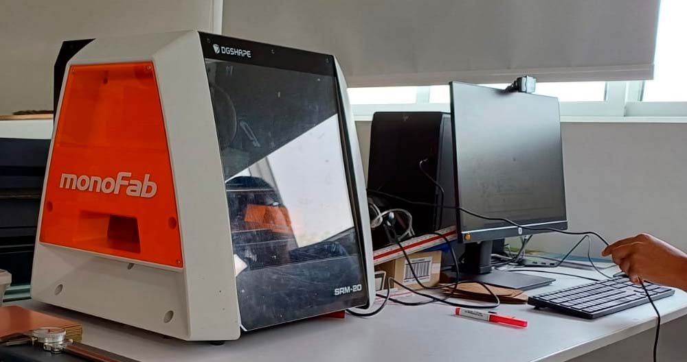
MILLING MACHINE
The milling machine that we have at the Universidad Cientifica del Sur is the MONOFAB SRM-20 that we will use for this week's assignment. Here are some specifications of the machine:
| WORK SURFACE | 232.2 x 156.6 mm |
|---|---|
| OPERATING SPEED | 6 mm/min to 1.800 mm/min |
| POWER CONSUMPTION | 50 w |
| SPINDLE ROTATION SPEED | 3.000 RPM to 7.000 RPM |

TRACE WIDTH TEST
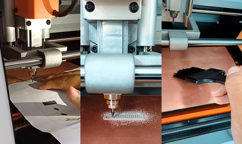
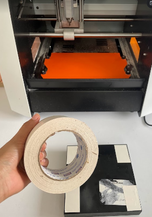
Before starting to cut the test we have to start with the preparation of the cutting area. Therefore, first we place the double contact tape on a small board so as not to work on the base of the machine, which is made of metal and can damage the cutters.
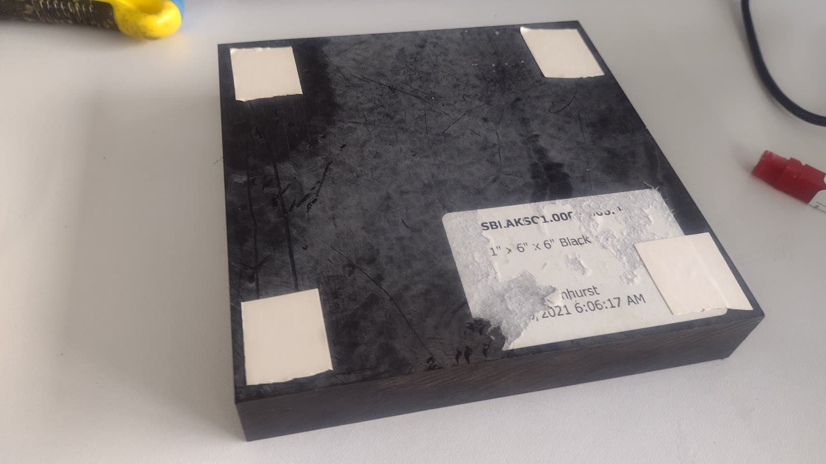
Then, we put more double contact tape on the board that we mentioned above so that we can stick the Printed Circuit Board so that they cannot move when the work is being done and we can take care of our milling cutter.
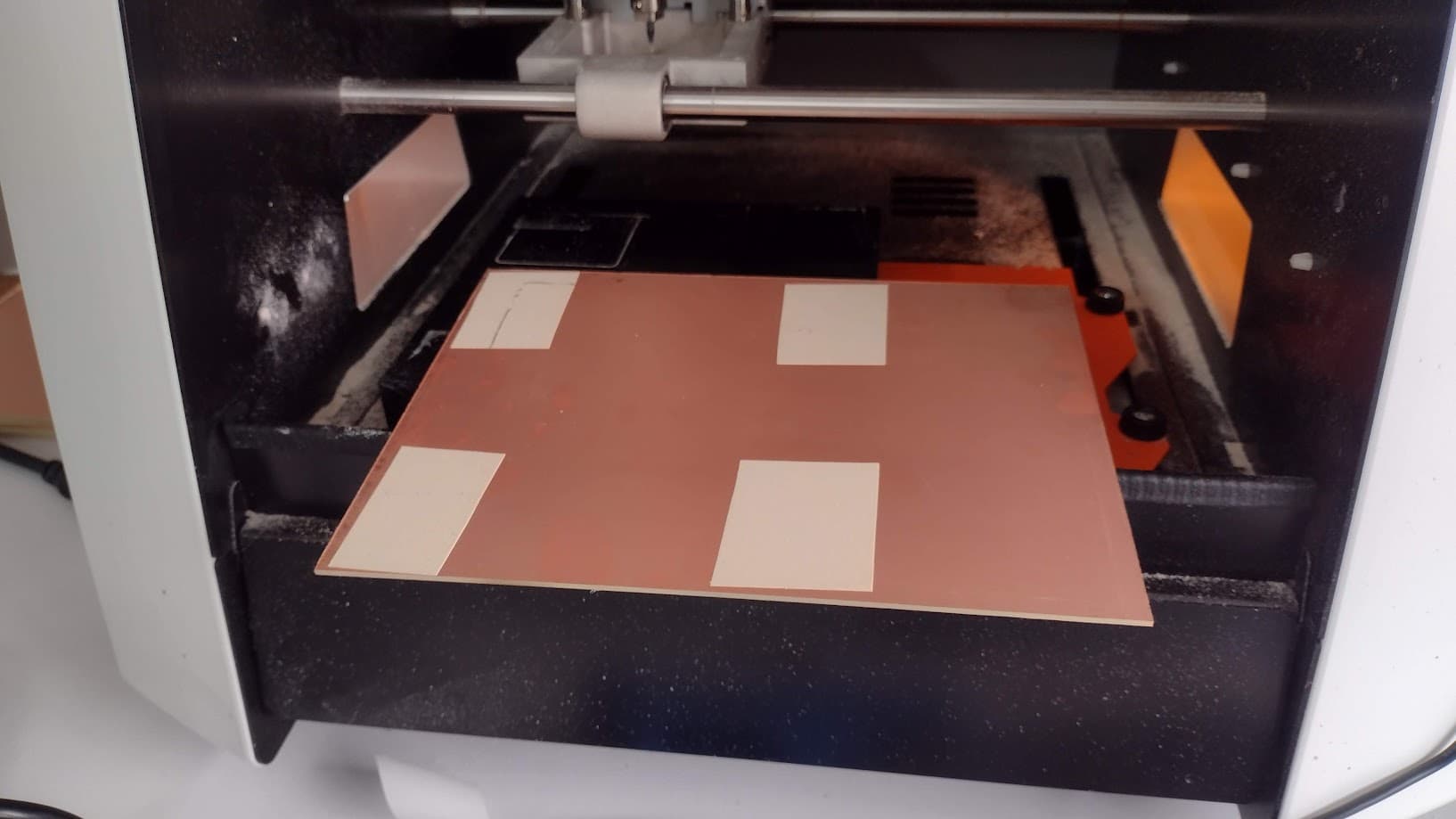
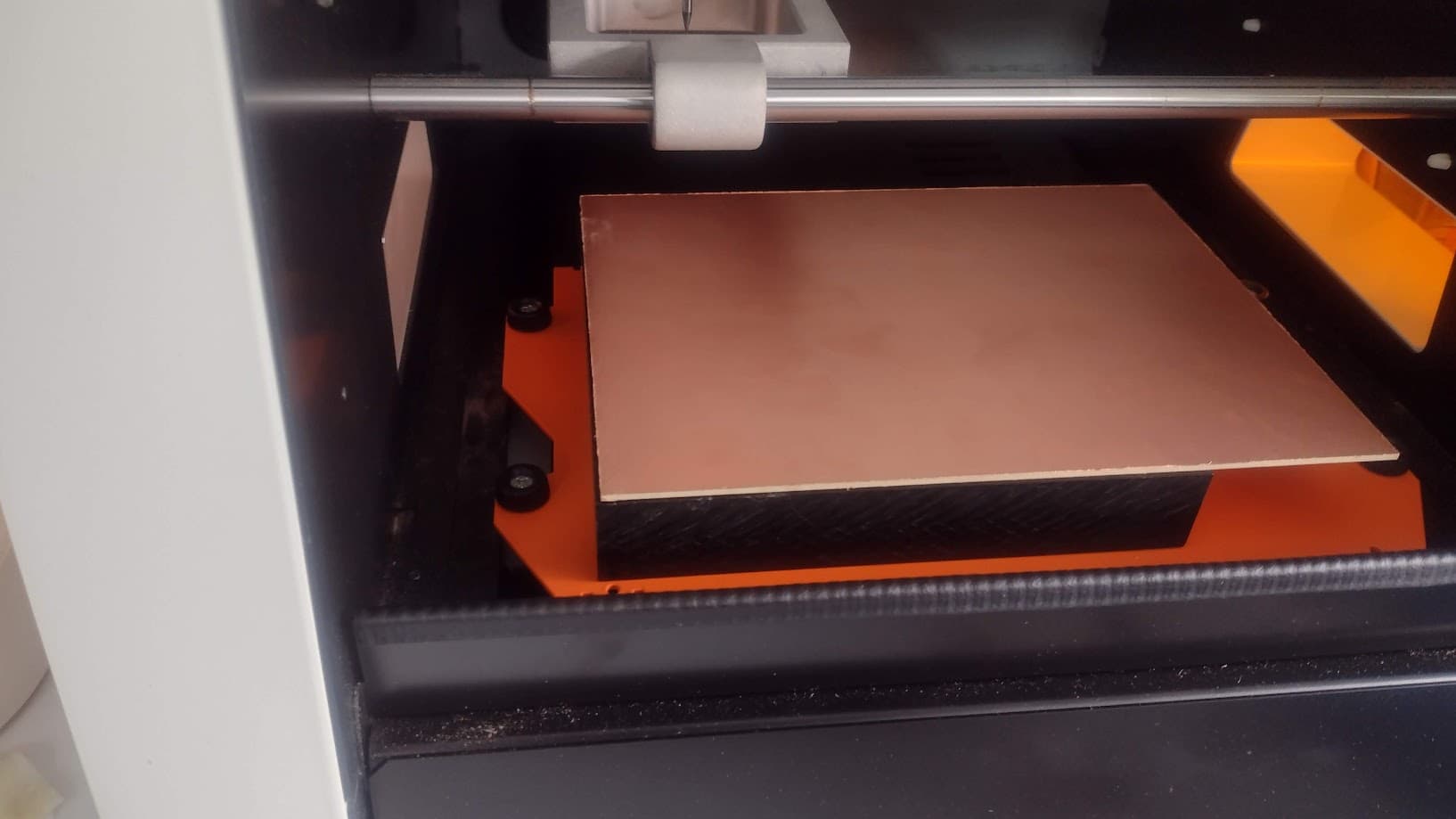
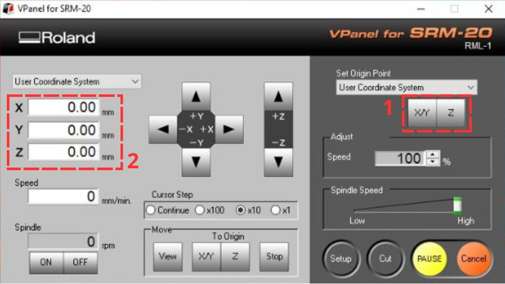
After having the circuit board correctly glued. We begin to configure the X, Y and Z axes of the MONOFAB . To do this, first we start configuring the X and Y axes where we want to start working and then, with the help of a bond sheet we can calculate the Z axis. Here we have to be careful because we can break the milling cutter if we don't do it right.
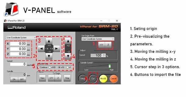
After obtaining the correct location of the X, Y and Z axes, we click SET ORIGIN since it will be the new origin of the machine and it can start cutting. That is where all the values will change to 0.00 mm and we would have the machine ready to start working.
LINE TEST
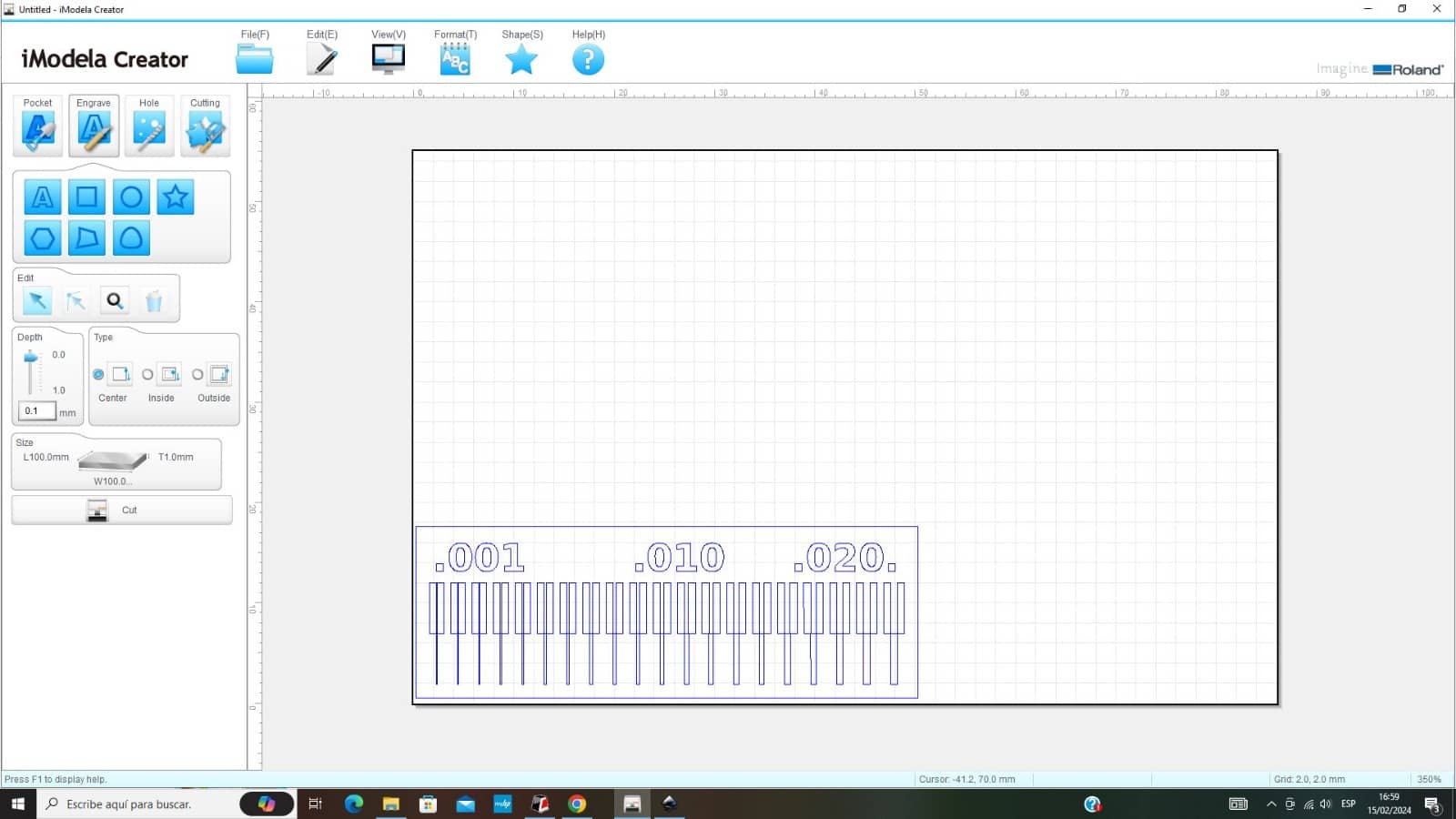
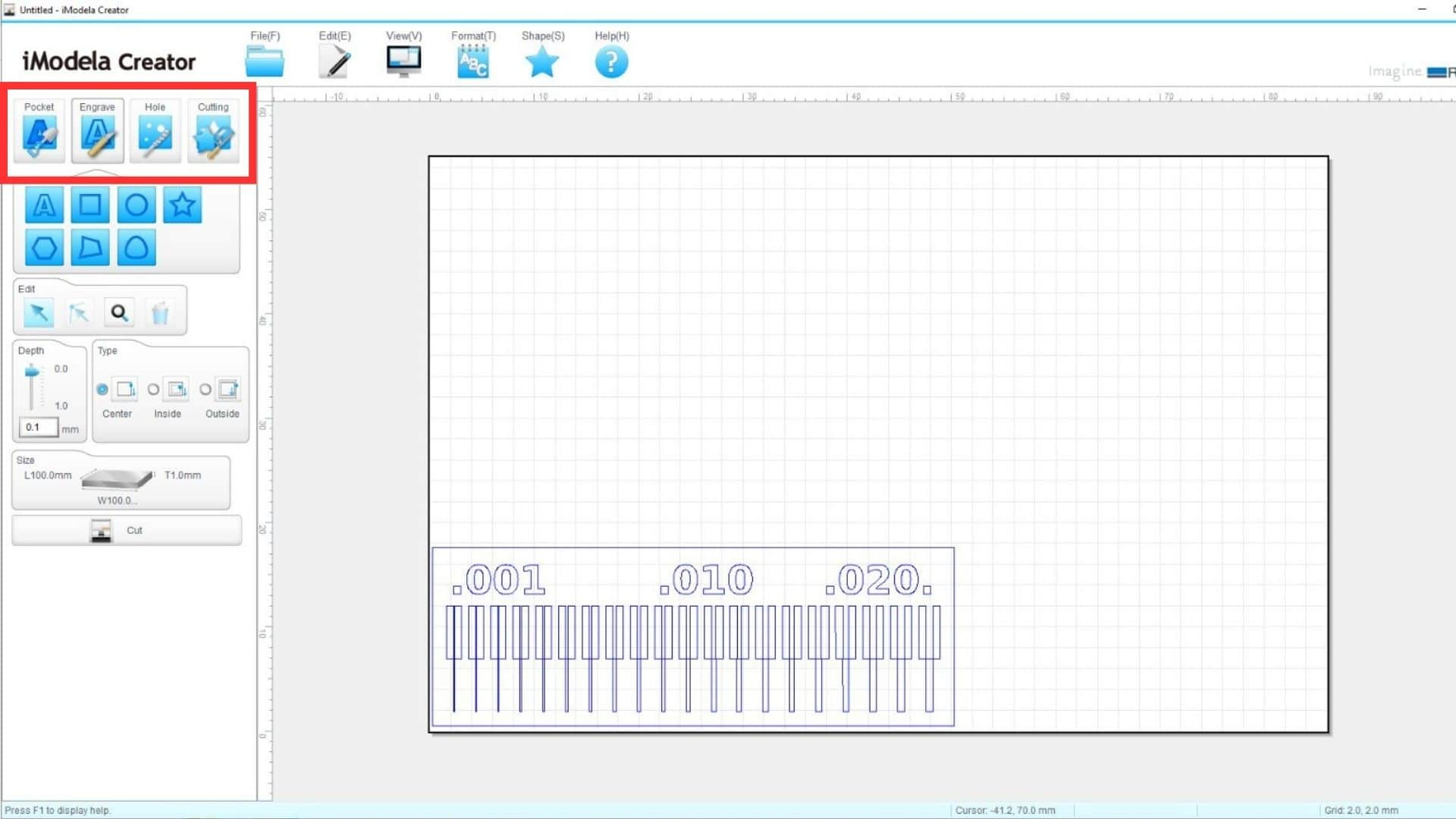
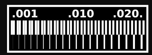
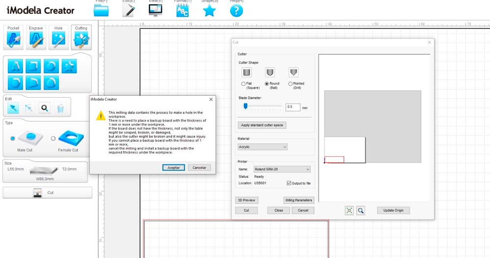
We will start with the line test, where we will perform the milling in the following image, remember that first we will perform the milling and then the cutting. For this first step we have to download the figure and pass it to the IMODELA CREATOR program , which is the program we use before moving to the machine program.
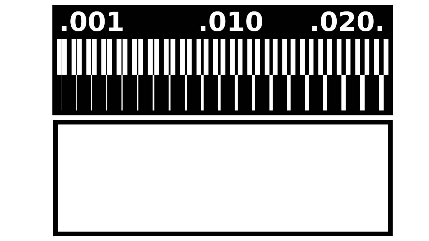
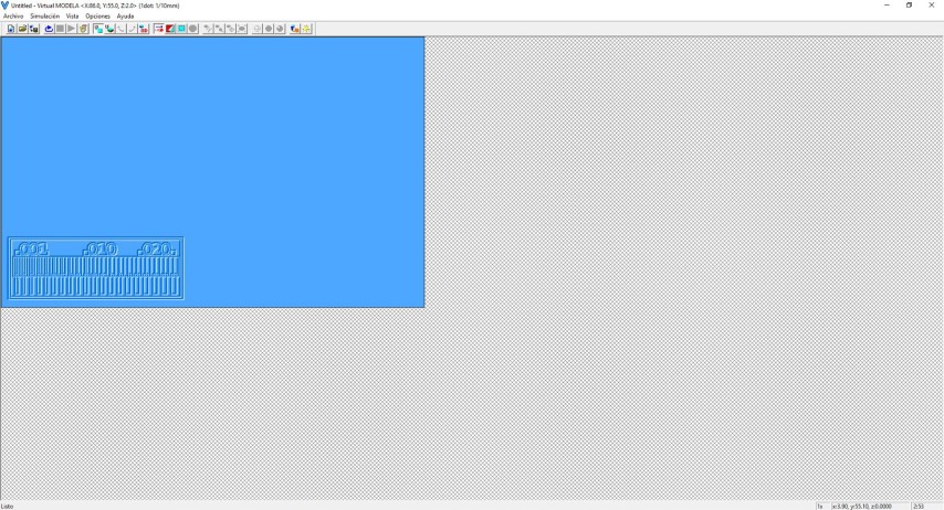
We first import the TRACES to IMODELA CREATOR to start milling and configuring the machine, remember that we will use the 1/64 drill bit for this occasion.

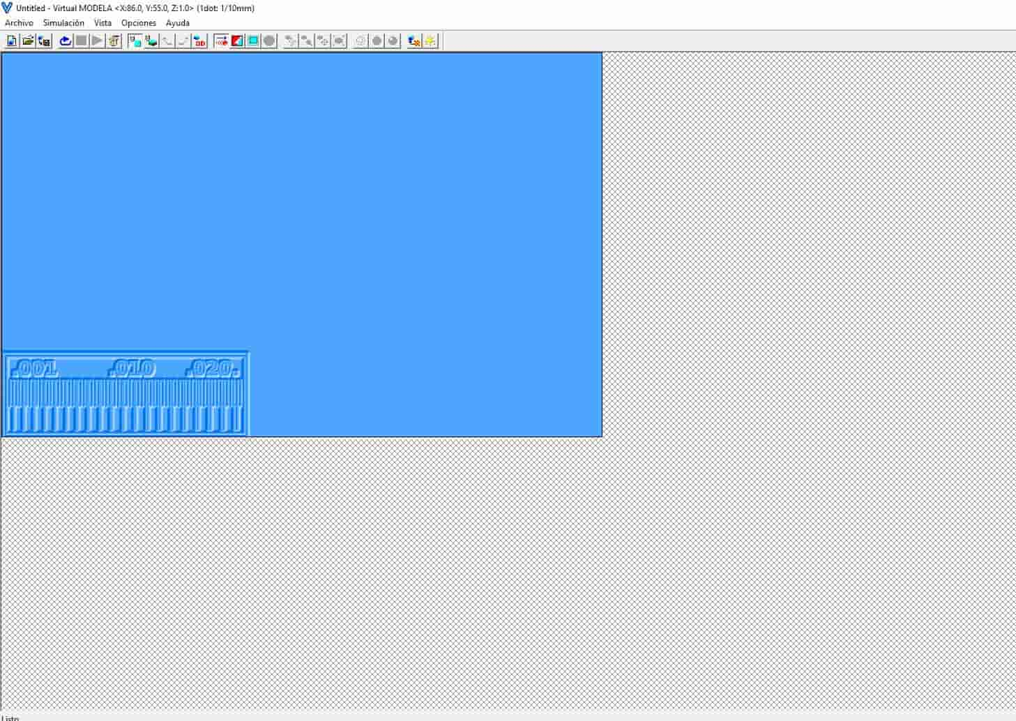
The IMODELA CREATOR program has the ability to show us a simulation of how the work we previously did would turn out. We thought it was good, so we sent it to be cut but the result was not what we expected.
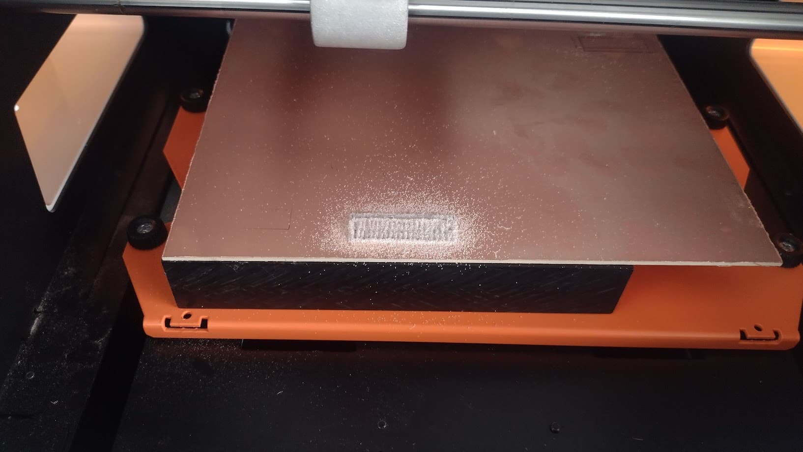
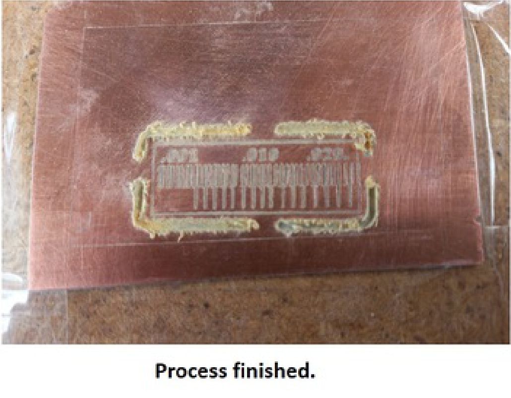
After importing, we proceed to cutting with the machine. In the first test we failed because the cut came out the other way around, that is, instead of cutting the part that we didn't need (black area), it started cutting the lines and numbers (white area) and this is the result. But the cut was precise and showed very well.

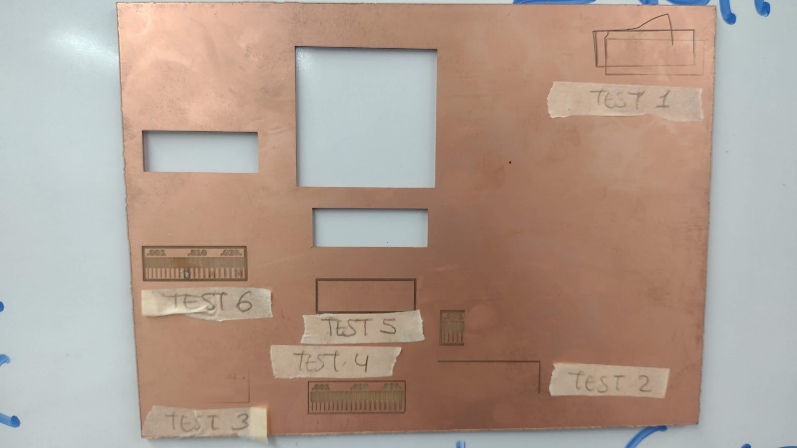
From here we had 5 more failures due to the frustration we had, we couldn't understand that we were wrong. Here is a photograph of the errors we had.
1. First test: Problems in the gluing of the copper plate as a base in the milling machine. The cut started to move and came out of the base, interrupting the movement and causing a bad test.
2. Second test: Problems in the inversion of layers, we milled the inverse of what we wanted to achieve, so the test came out wrong, problems in the layer configuration in the Cut studio.
3. Third test: Configuring the modifications in the engrave and pocket, it was still not possible to clean the surplus and the result was the inverse.
4. Fourth test: We did it! the cut values were modified to obtain the inverse, it should be noted that we have better control by changing the color of the layers.
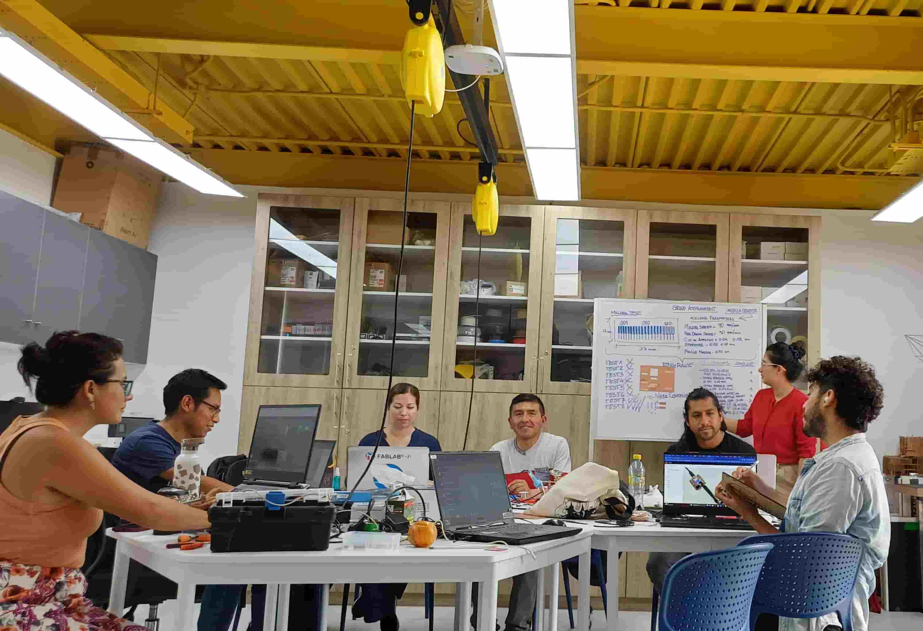
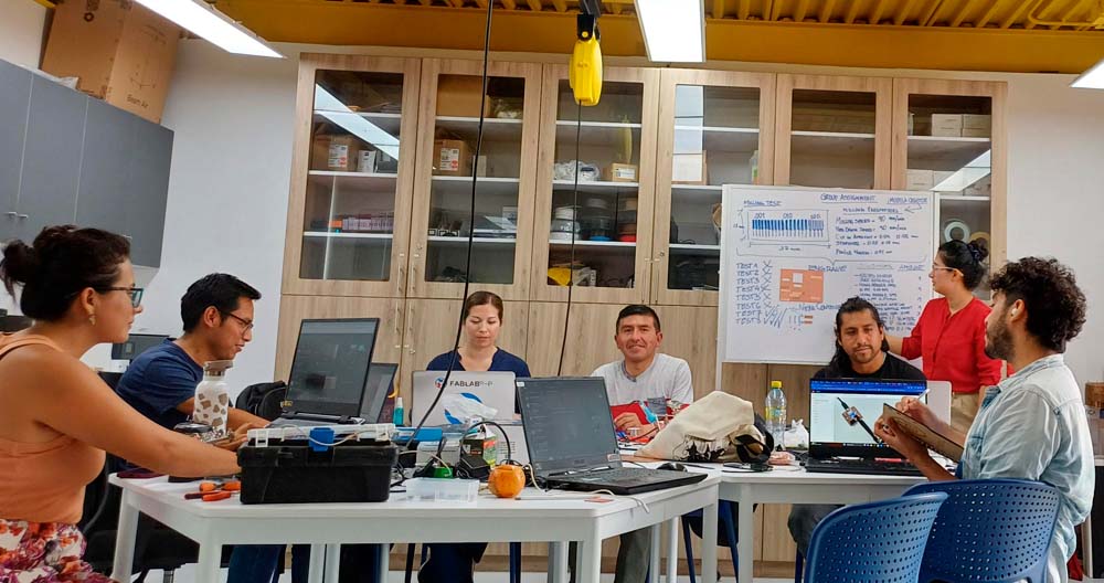
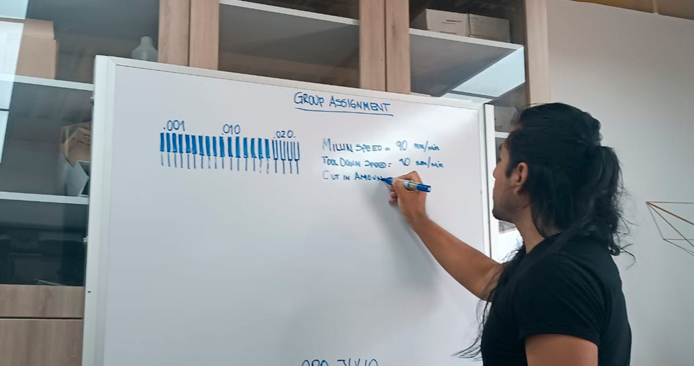
We talked with each other and agreed to review each procedure we are doing. We left the machine and began to discuss the failures and analyze each step we were taking. So we met, understood through whiteboard support and understood each failure.

After taking a breath, we were able to understand and discover what the error was, but we were not able to achieve the objective. However, we were able to achieve what we were looking for when we sent the file to be milled and happily it turned out well and what we wanted for the machine to cut through the OFFSET. The problem was that we did not realize that in the software we could make changes so that the milling cutter cuts OUTSIDE, CENTER OR INSIDE and we configured it correctly and the test came out that was close to the objective.


Then, we also discovered the difference between POCKET, ENGRAVE, HOLE AND CUTTING that the software offers us. Then we made the corresponding configurations to make the test look like what other colleagues presented last year and we achieved it.


Maria Angela Mejia
Testing in the Milling Machine
To test the parameters to use to mill the PCB path, we worked as a team and went to the Southern Scientific University (UCSUR) Fab Lab which is located in the Architecture Faculty of the university, in Chorrillos district, in the city of Lima, Peru.
Milling Machine
The machine used was the Roland monoFab SRM-20. It is a compact 3D milling machine used for prototyping in chemical wood, acrylic and modeling wax. It usually includes the MODELA Player 4, iMODELA Creator and ClickMILL softwares. Additionally, it uses a VPanel for operating it.
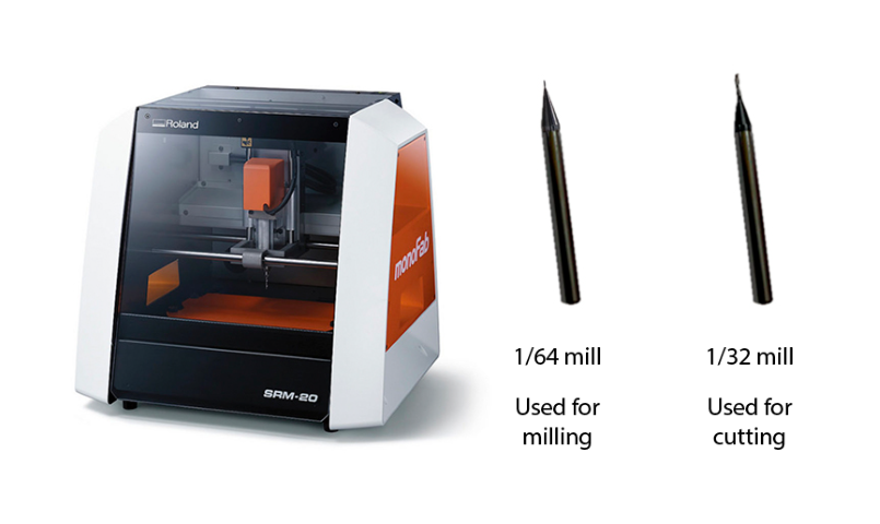
Image Tranfer
There are several ways to transfer the copper path on the PCB: photographic method, silkscreen method, thermal transfer method, CNC milling method, among others. In this case, we worked with the latest method to manufacture the tests.
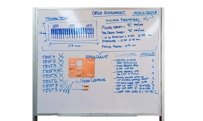
First of all, we tested the milling precision with a traces test. We worked in the iMODELA Creator software to configure the parameters of the milling machine.

We configurated the test parameters:


Once the test file was set up, the milling cutter had to be calibrated with the paper method before the test file was manufactured. When the machine was ready, the test was sent to be milled.
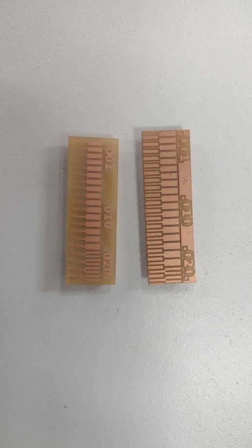
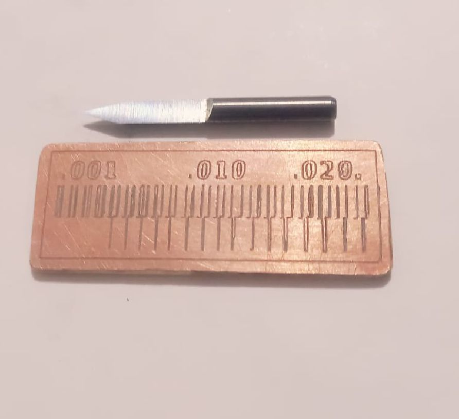
Finally, this was the result (after many attempts).

Silvana Espinoza
Testing in the Milling Machine
A week before my partners and I were looking for the electronic components because we knew that in Peru they did not sell everything complete, then with the help of Vanessa we managed to get the Xiao, with the help of the Fab Lab of Universidad Cientifica del Sur, we were able to make the boards and solder everything in the week.
MACHINE MONOFAB SRM-20
Milling machine we used at the Universidad Científica del Sur is the MONOFAB SRM-20. I have already told you about the advantages and disadvantages of this machine. Here are some specifications of the machine:
MILLING 1/64 AND 1/32
We used the 1/64 and 1/32 milling cutters that were very important in the manufacturing process. Here you have a picture of each of them, you must be careful when calibrating because you can break, also remember that when calibrating have an hour to leave a space between the cutter and the base, then remove the hour and lower x100, another way is to put the cutter a little more to the bottom, and then lower and release the cutter in the short space you have between the base and the entrance of the milling cutter, and adjust about a half inch.
First of all, we tested the milling precision with a traces test. We worked in the iMODELA Creator software to configure the parameters of the milling machine. Changing the milling cutter and then calibrating
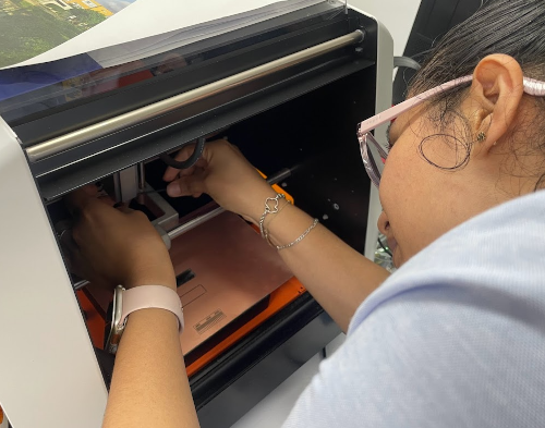
We place double contact tape on the board that we mentioned earlier so that we can glue the printed circuit board so that they cannot move when the work is being done and we can take care of our milling cutter.
For this first step we have to download the figure and pass it to the IMODELA CREATOR program, which is the program that we use before placing the configuration and the characteristics of the material that we will use.

After having the circuit board correctly glued. We start configuring the X, Y and Z axes of the MONOFAB . To do this, first we start configuring the X and Y axes where we want to start working and then, with the help of a bond sheet we can calculate the Z axis. In this step we have to be very careful because we can break the cutter, so patience.

The line test, where we will perform the milling, remember that first we will perform the milling and then the cutting.


Here we can see the difference between the last tests, where we were able to achieve the objective we were asked to achieve for the group work. We understood the processes, configurations and we were able to obtain our board test...finally.

Cristian Loayza Egoavil
Characterizing design rules
The group assignment was carried out at the facilities of the "Universidad cientifica del sur" in the fab lab.
For the group task we planned how we would perform a milling test from an image in .PNG format that we downloaded from the academy work files.
The milling machine that we use is the monoFab SRM-20 Desktop Milling Machine
We set the parameters in IMODELA DREATOR, it shows us the simulation and we do the tests.
We did some tests with different parameters because it is the first time we work with the Mono Fab milling machine and after 6 failed tests we were able to perform 2 successful tests, it was a great achievement for all of us.
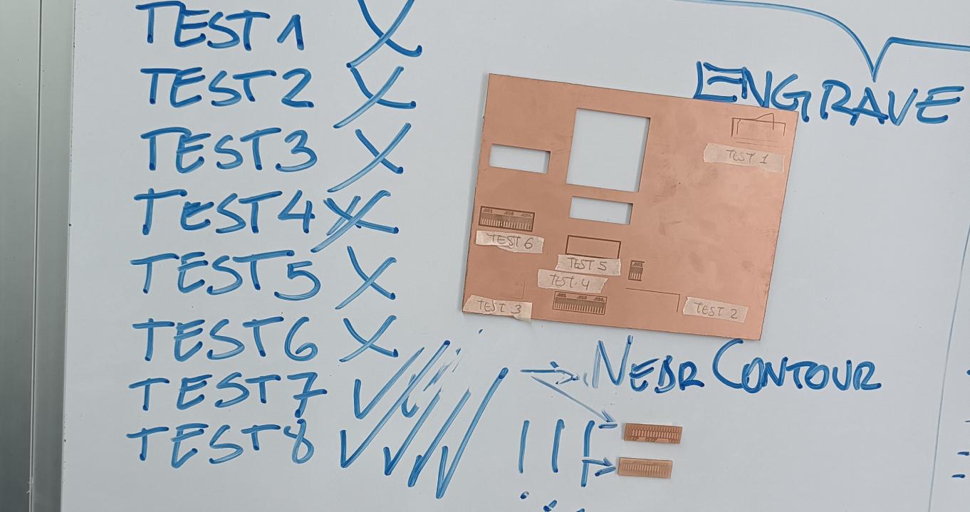
After all the tests we did, this is the final result.

Workflow for sending a PCB to a board house
To know the manufacturing flow of a PCB in China, we chose the PCBWAY company and its online quoting system.
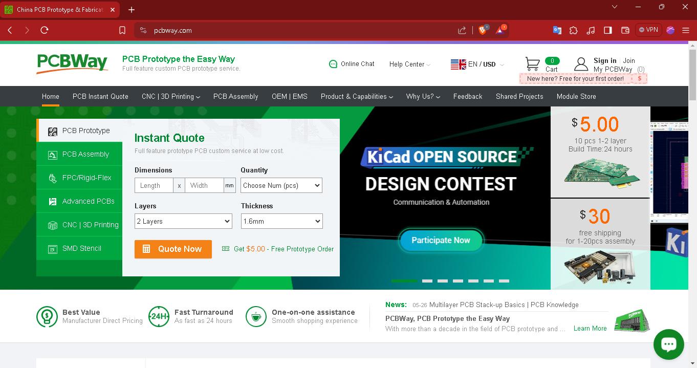
The first step is to register on the pcbway website, the process is free.
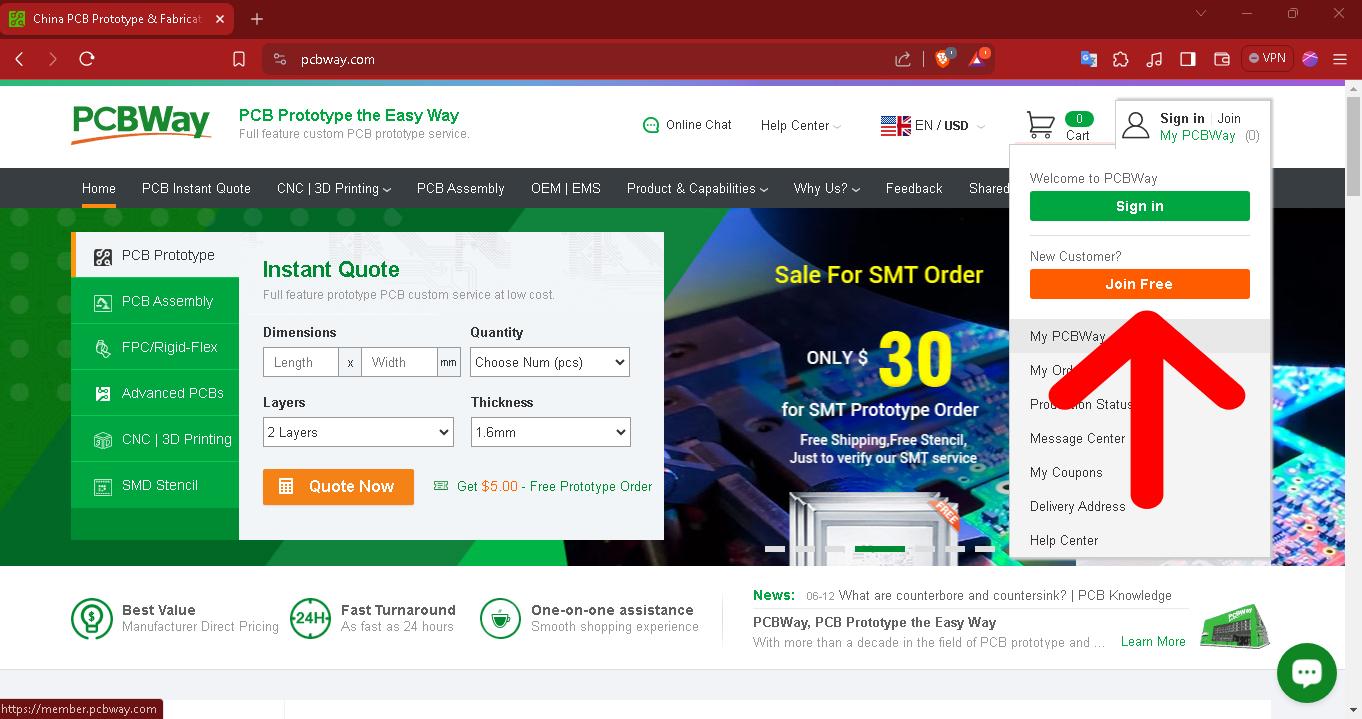
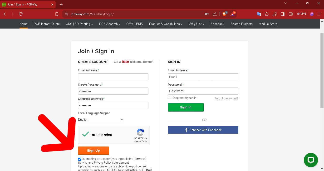
Registration is through a form as in any registration system.
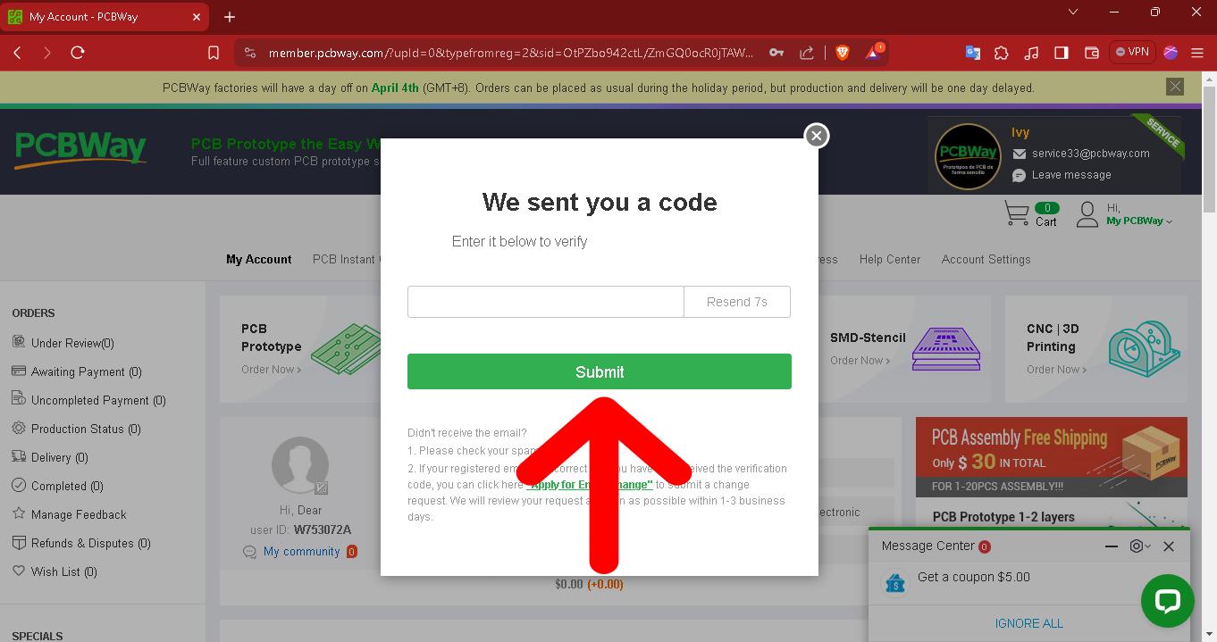
To complete the registration, the system will send us a verification code to our registered email and we must copy and paste that code to finish the process.
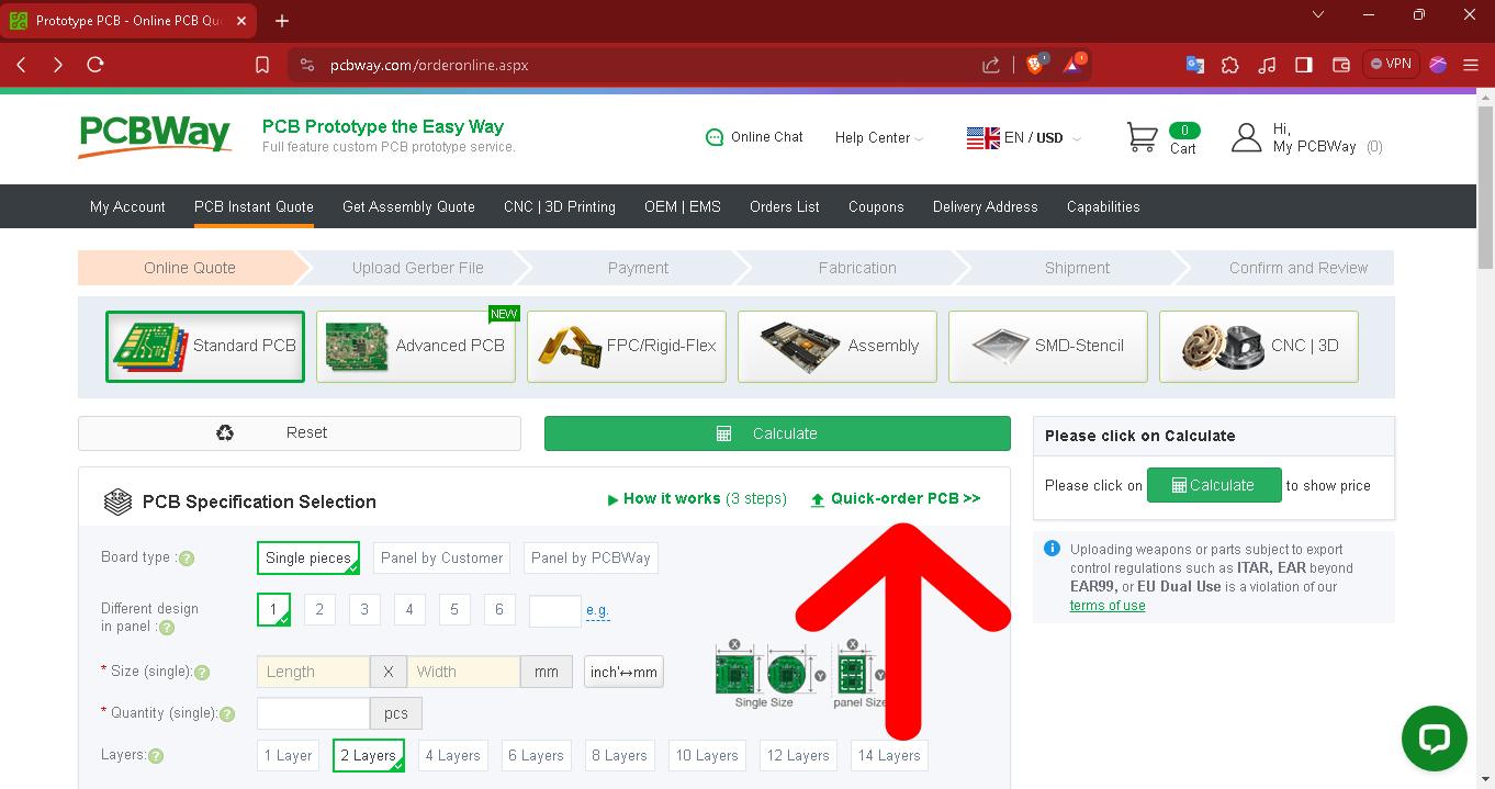
We must enter this tab to get an instant quote.
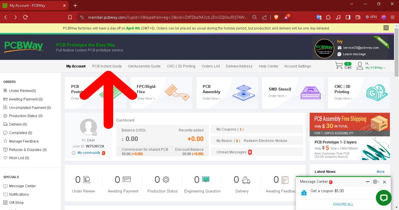
Then in the window we must enter the PCB quick order tab.
Within the window we must upload the GERBER files
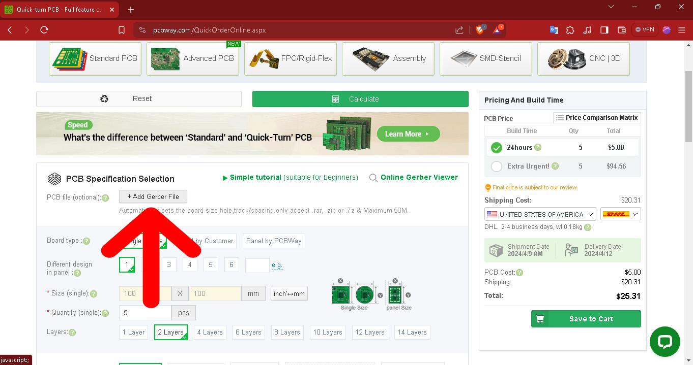
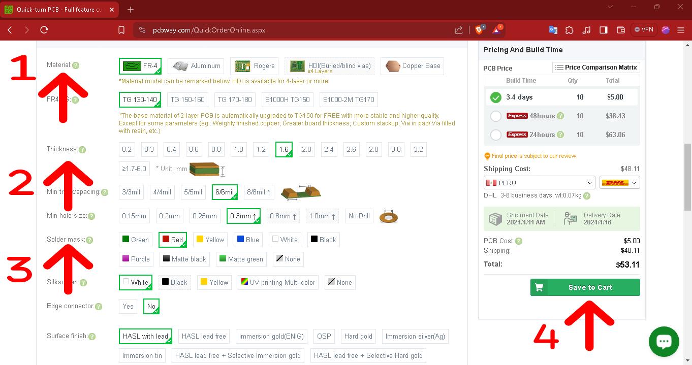
The system detects the files and gives you many more options to customize your PCB.
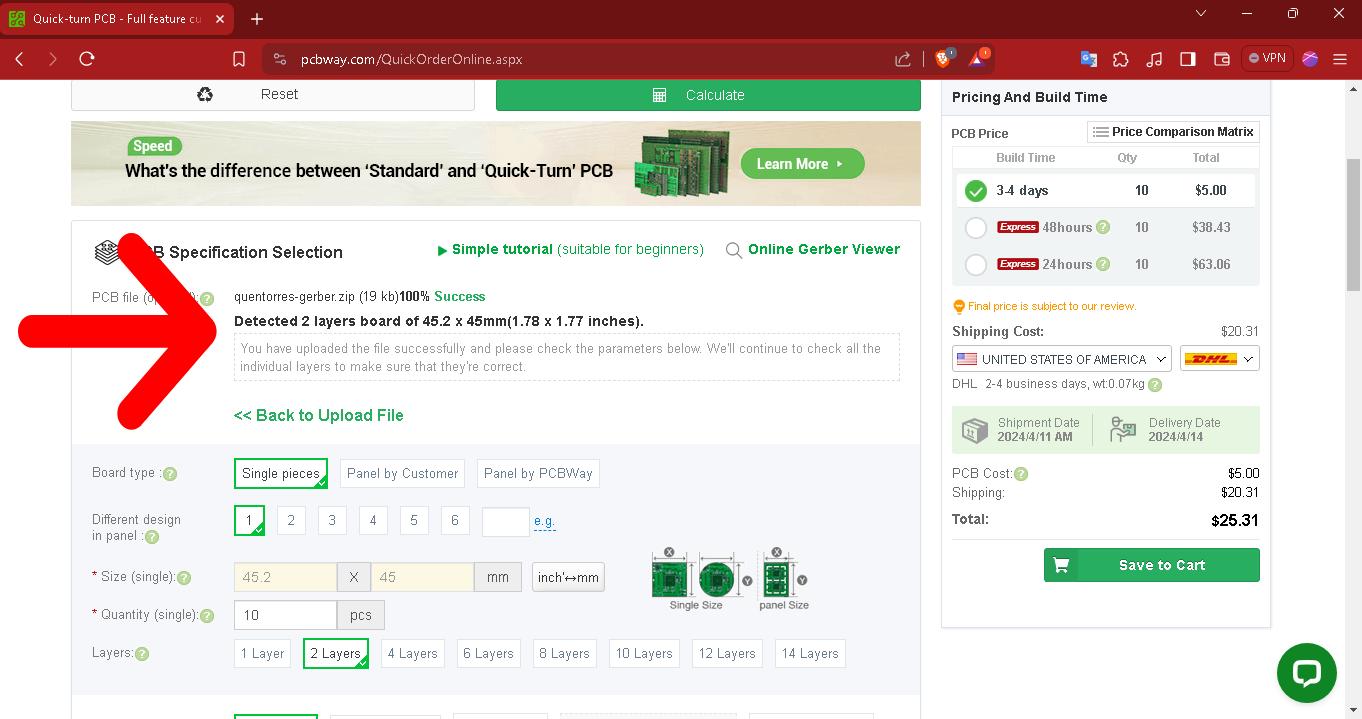
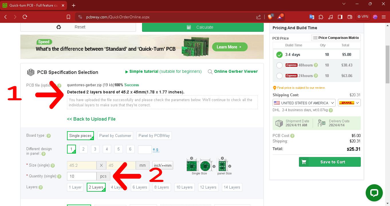
1. The system loads your designs, detects them and validates them as approved for customization.
2.We choose the number of pieces we want to manufacture, in our case we choose 10 units since it costs the same as 5 units.
1. We can change the PCB material, of course each material varies in cost.
2. We can also choose the thickness of the PBC.
3. We can also choose the color of the PBC.
4. Once the PCB has been customized, we select the destination country, verify the total cost and proceed to make a payment like in any online store and wait for the PCB...how great that all this can be done quickly.
Group 2:
- Ronal Vilca
- Wilber Giron
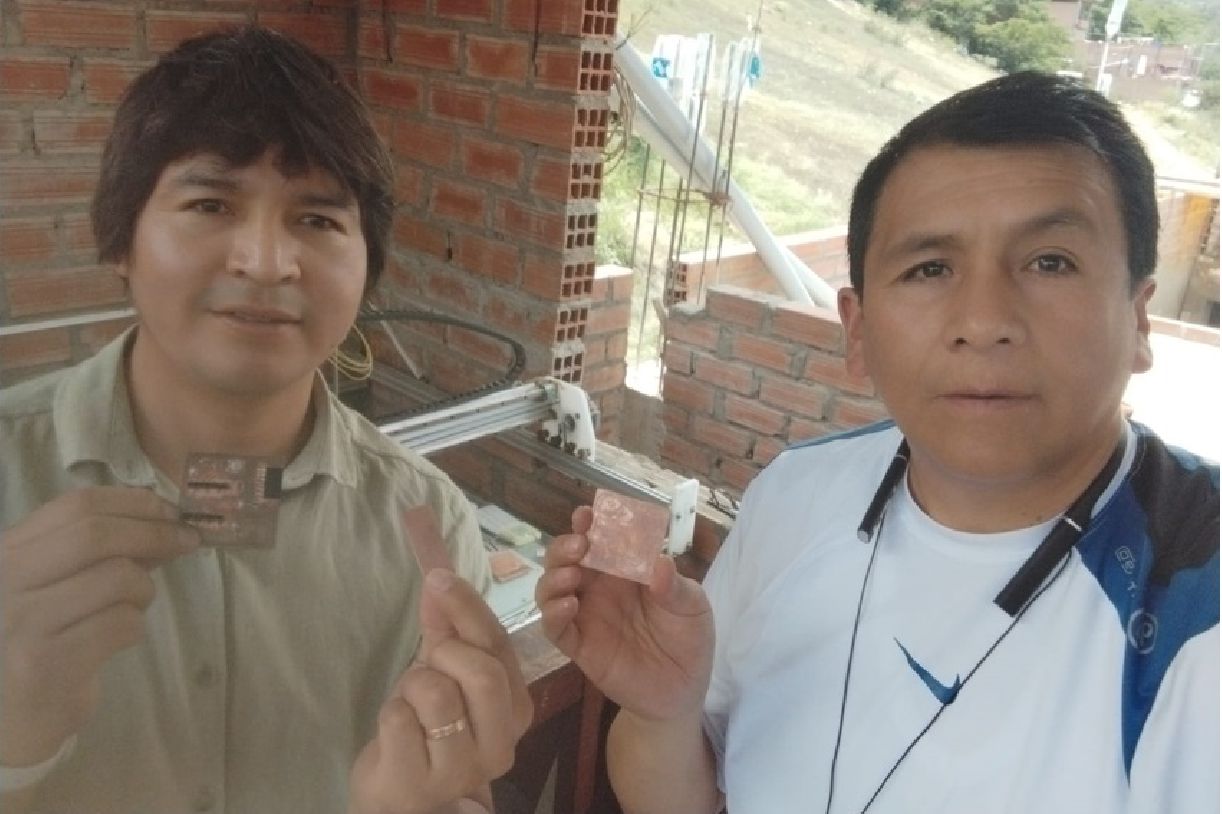
With colleague Wilber from Pasco.
Ronal Vilca
This week we focus on electronic production using a CNC router. Our first team task was to test and calibrate the machine parameters. Once this stage was completed, we proceeded to perform the necessary tests. Once the board was ready, we proceeded to solder the electronic components and then programmed the XIAO ESP32 C3.
To carry out the tasks assigned this week, I used a home-made CNC machine which will be described below:
- 500 watt Splinde motor.
- Four 2 amp nema 23 motors.
- JKD2060H control driver.
- Working speed 8000 RPM.
We carry out group work at home using a machine manufactured in Peru, specifically in Huánuco. We did it with my colleague Wilber Giron, who resides in the city of Pasco.
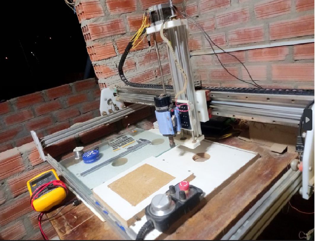
Homemade machine.
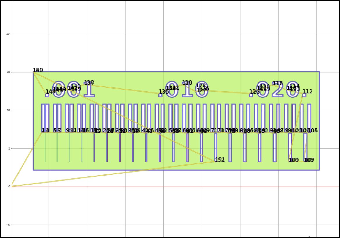
To carry out the tests with the machine, we first download the file from the example provided in class. Then, using the Flatcam software, we import the downloaded image.
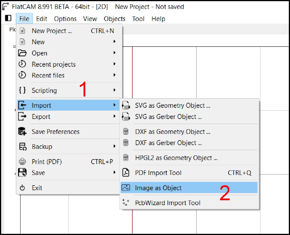
Selecting the format to import.
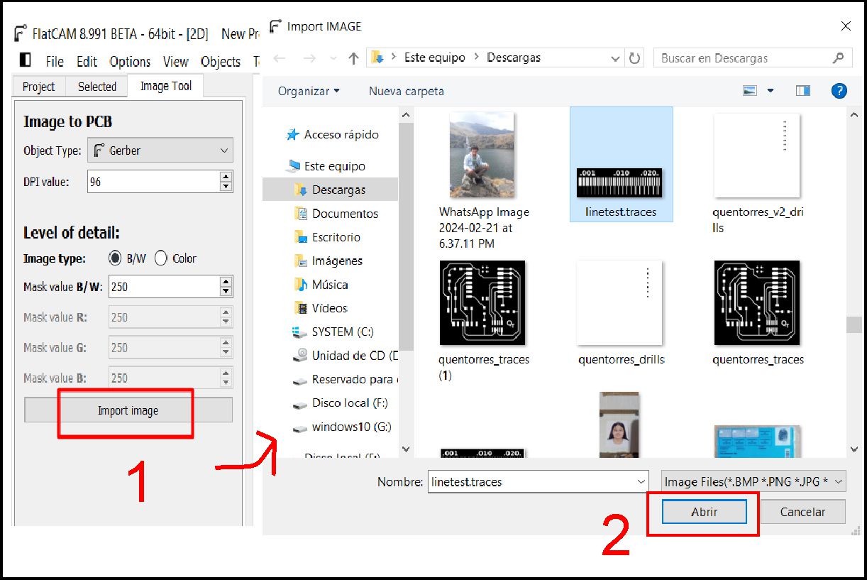
Importing downloaded image for testing.
As you can see, the downloaded image was imported successfully. Next, we proceed to configure the tool, in this case, a 0.1 mm 30° "V" type milling cutter is selected.
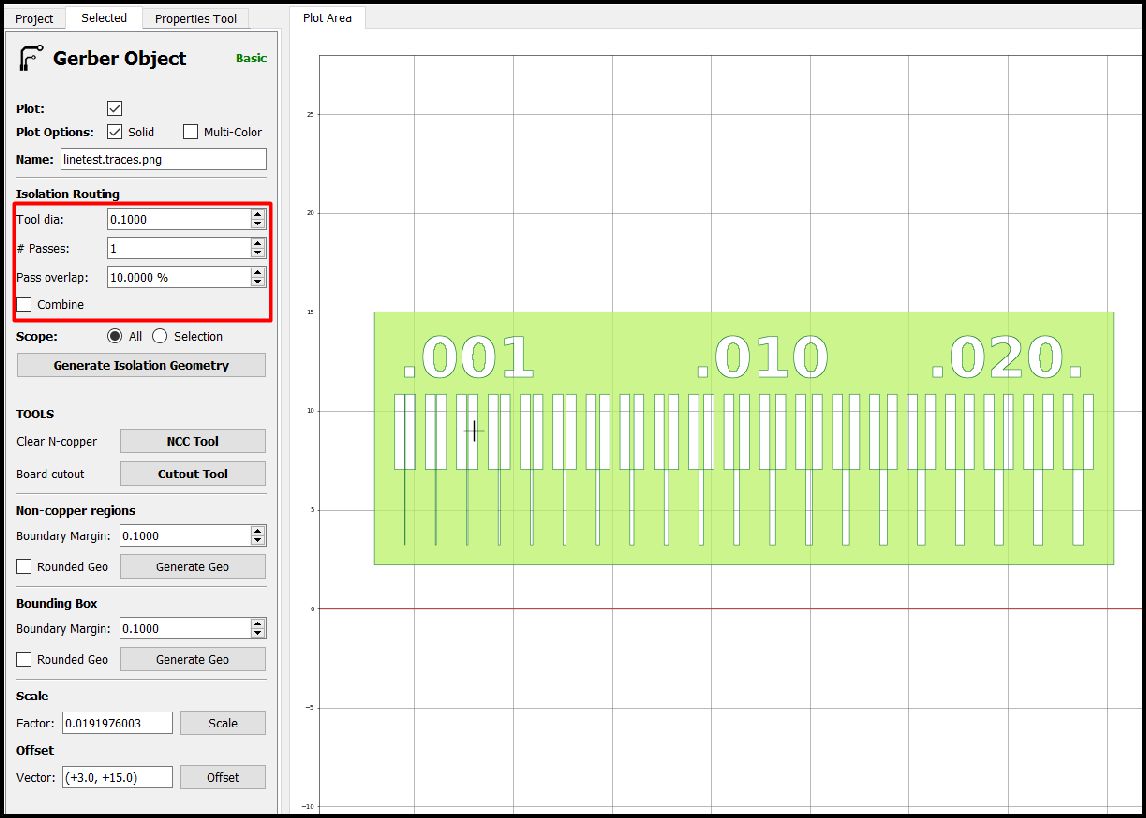
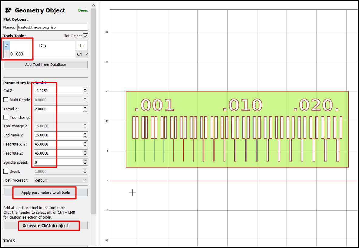
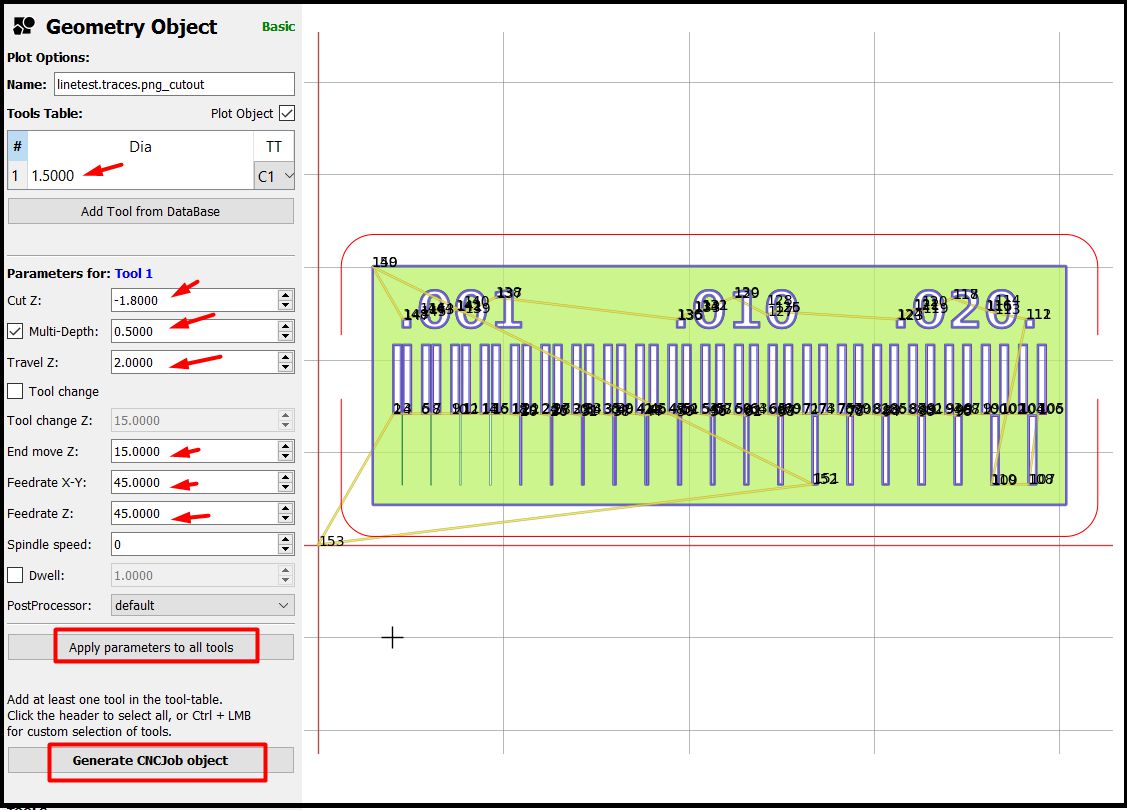
Subsequently, a window will open where we establish the speed parameters for the X-Y and Z axes, as well as the tool size, material wear and displacement after each operation of the CNC machine.
The movements in the X and Y axes are 45 steps per millimeter, while in the Z axis they are 15 steps per millimeter. We use a roughing of -0.025 mm, which is enough to remove the material in a single pass. Furthermore, when moving to another point, the movements in the Z axis are 2 mm.
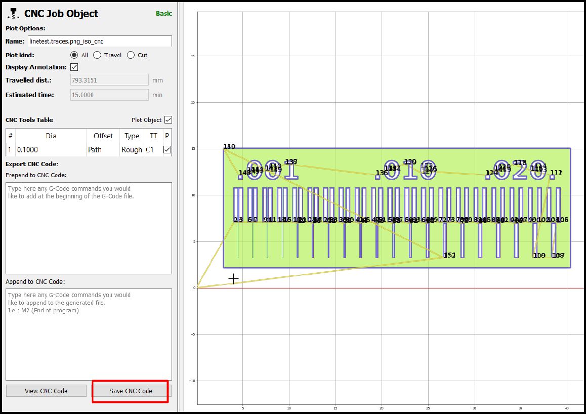
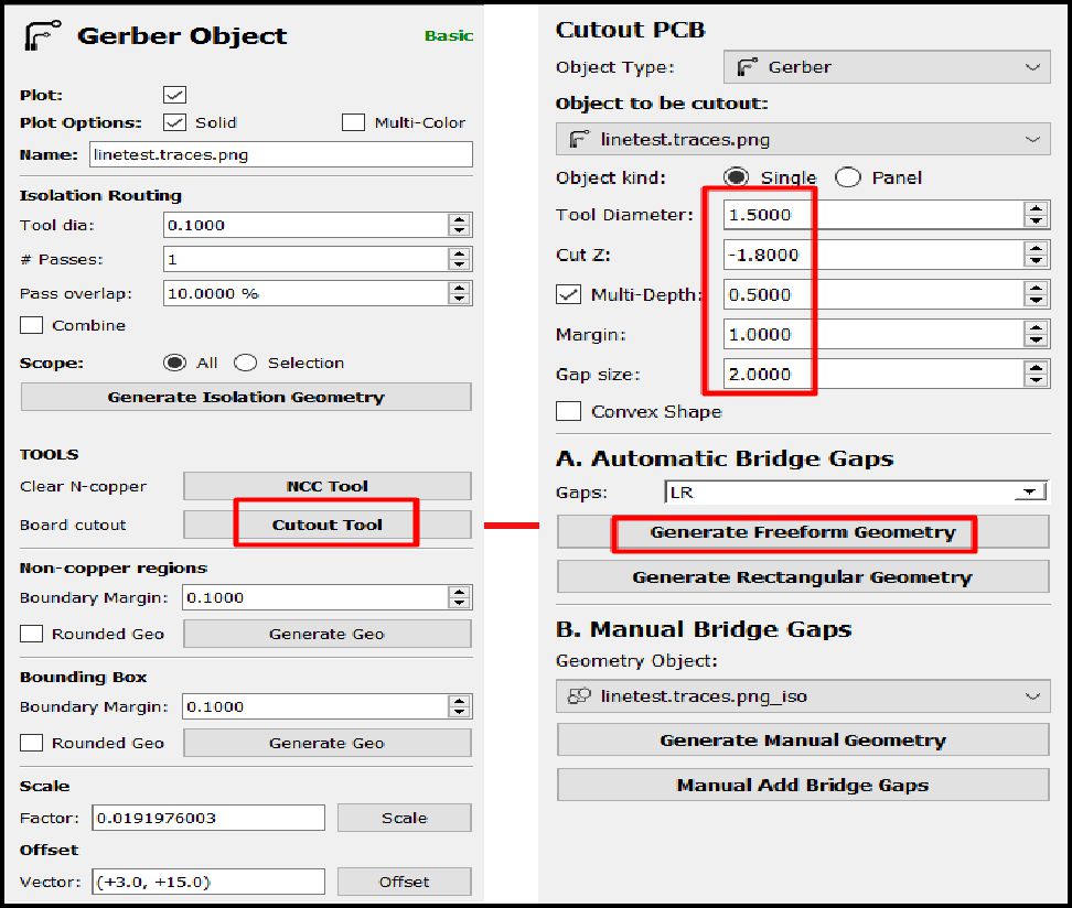
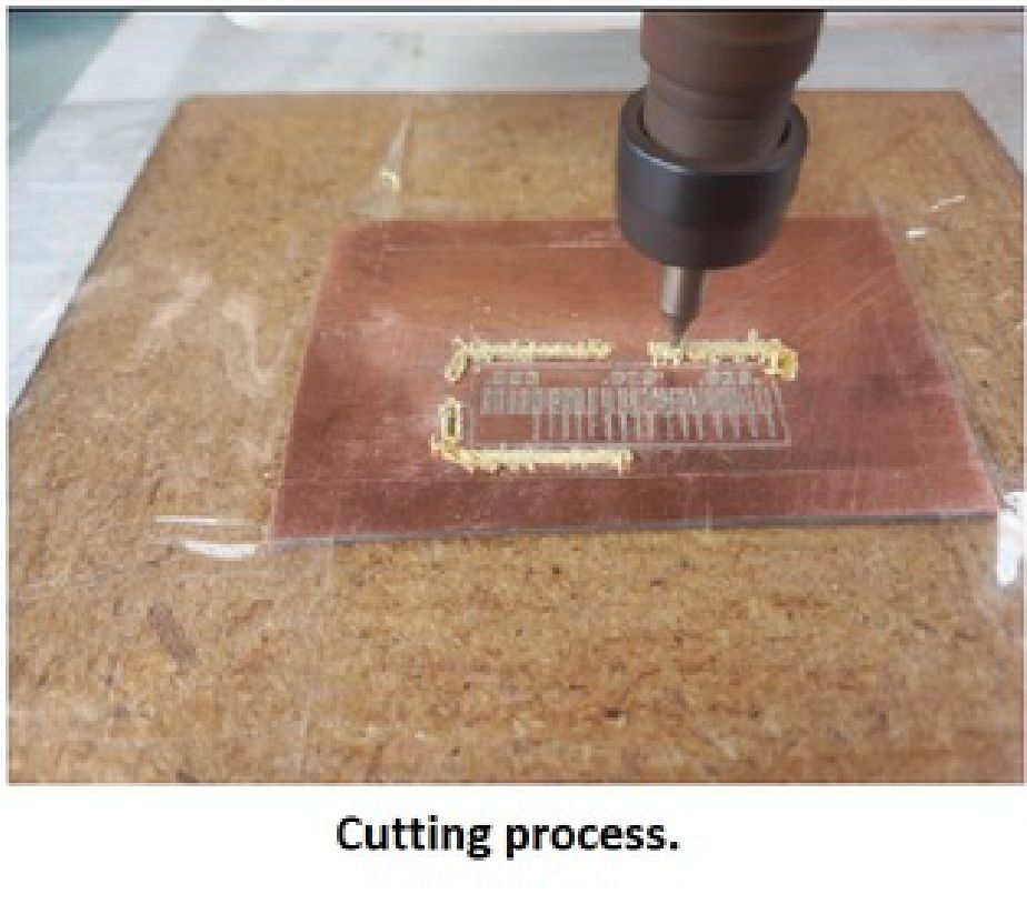
The next step is to cut the plate. To do this, we proceed to change the tool for a 4-flute type milling cutter, with a diameter of 1.5 mm. The specific parameters for this cut can be seen in the following image.
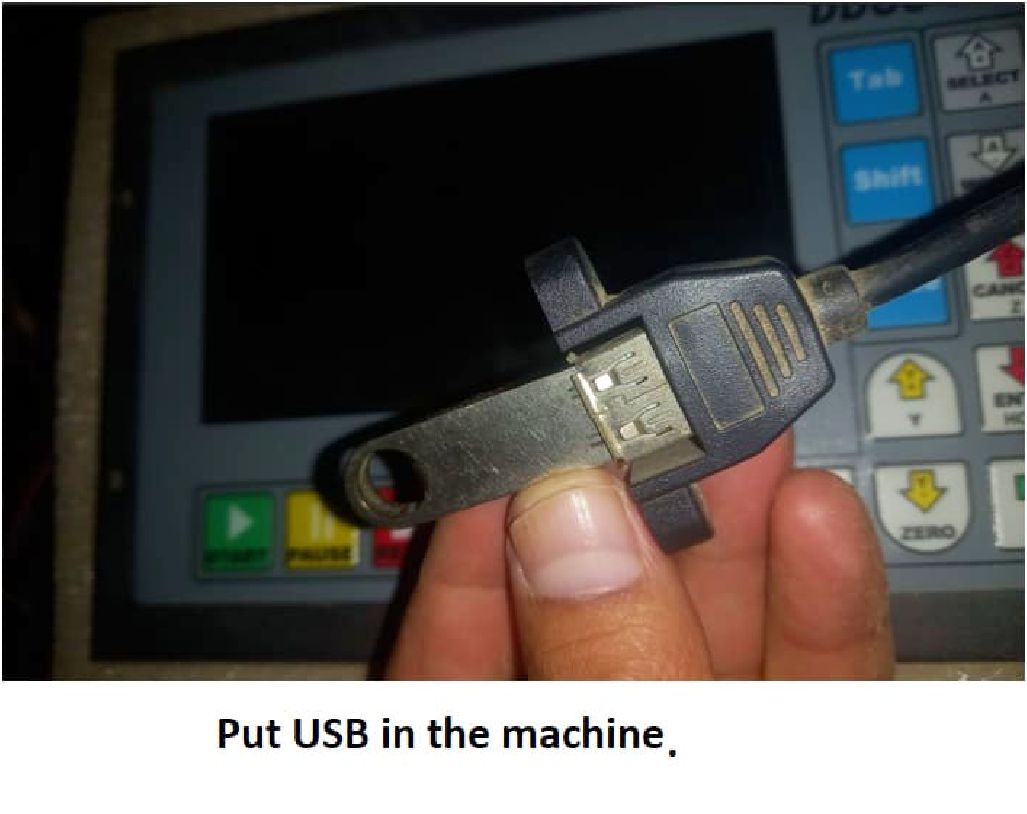
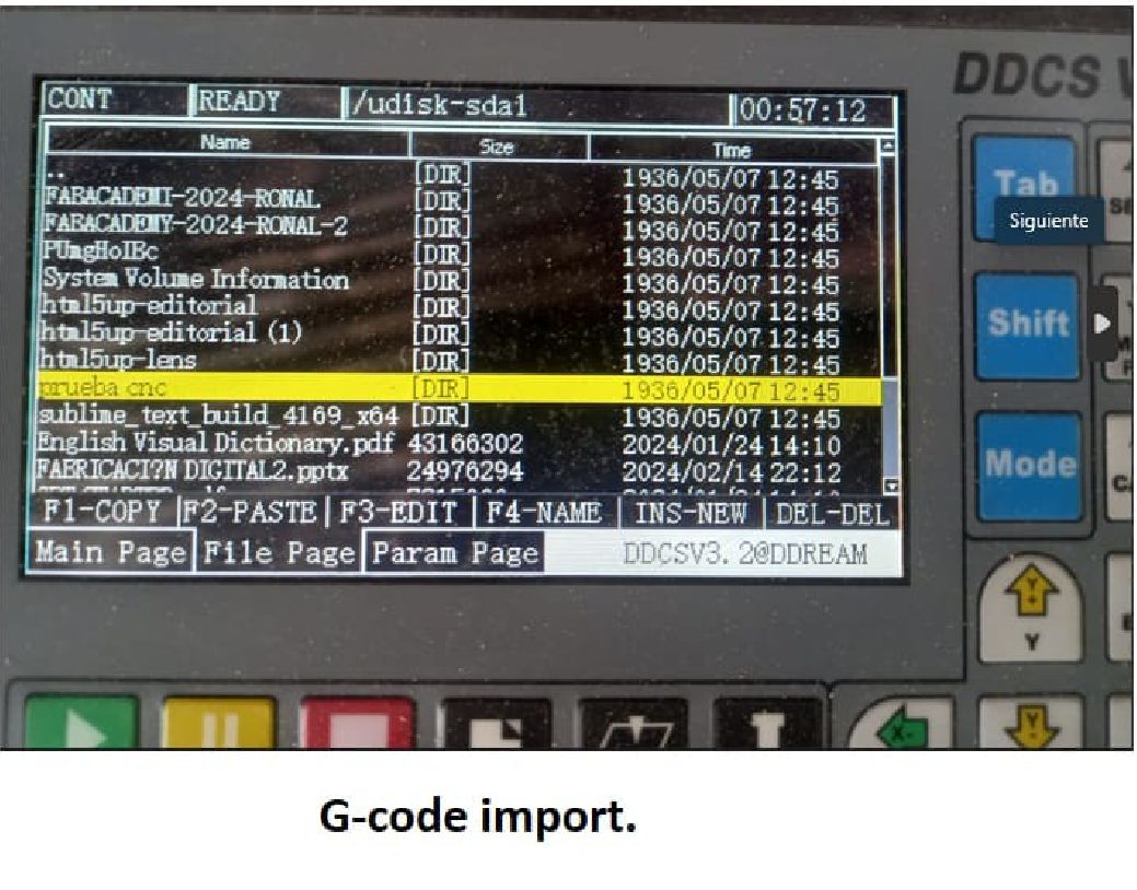
The next step is to save the generated G-code to a USB and then insert it into the machine for the process. Once on the machine, we select the file and import as shown in the following image.
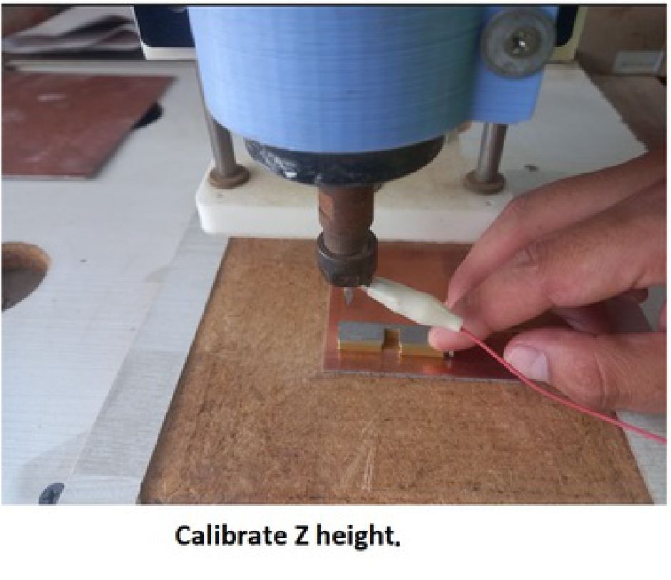
Once we have located the machine and placed the material, the next step is to calibrate the height of the tool in relation to the material. Once this calibration is completed, we proceed to start the process.
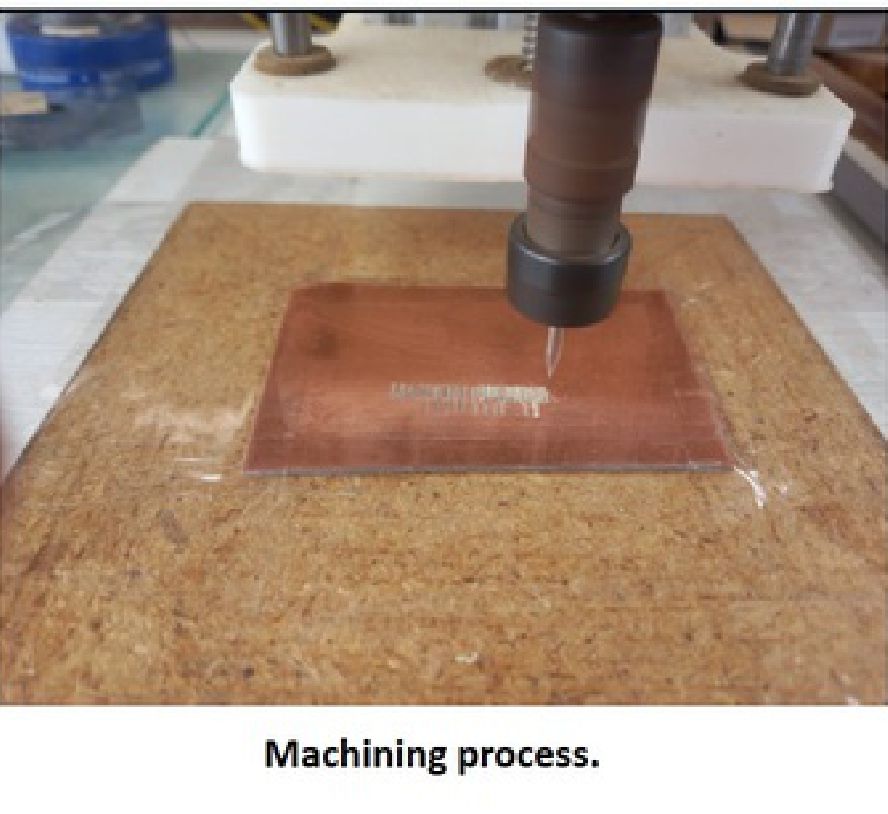
After completing the machining process, the next step is to clean the work area and make any necessary improvements. Subsequently, we prepare to carry out the next task, which is the personal assignment.
Conclusions
What I have learned this week is that it is crucial to calibrate the machine in terms of the travel speed in the X and Y axes. This is vital because it largely depends on the structure of your machine and, above all, the spindle. In addition, it is important to accurately adjust the material roughing level in my case to 0.025mm of Bakelite material, since if it is done too deep, there is a risk of breaking the cutter. There is also the possibility of removing or cutting some layout tracks that are too small. It has been a very profitable week, now that I understand all these parameters, I am ready to approach my individual task with confidence.