Characterize your lasercutter's focus, power, speed, rate,
kerf, joint clearance and types
Individual assignment:
Cut something on the vinylcutter
design, lasercut, and document a parametric construction kit,
accounting for the lasercutter kerf,
which can be assembled in multiple ways,
and for extra credit include elements that aren't flat
Let's start
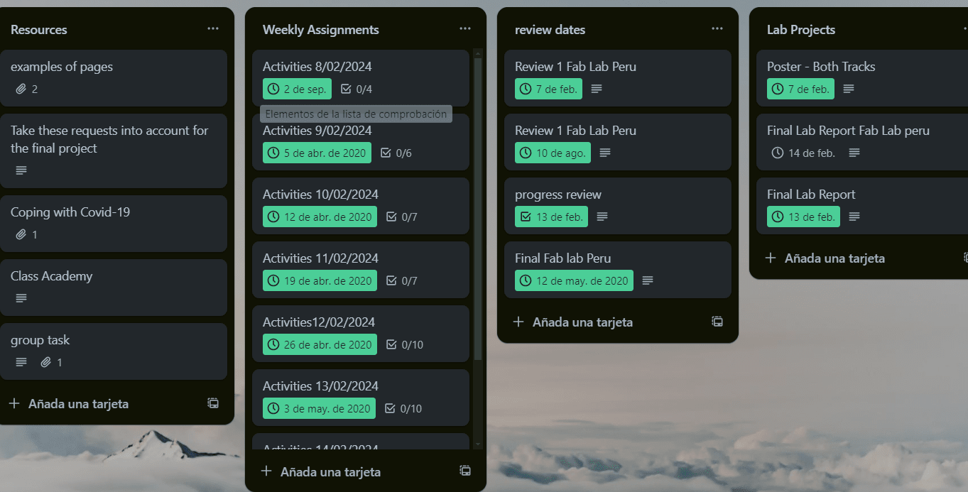
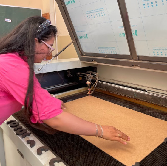
The machine I use is the C4V model 1390 laser cutter from the Fab Lab of the Institución Emblemática Melitón Carvajal.
Advantages:
Graphic panel Stores up to 500 designs Intuitive environment easy operation
Work table with bee panel and bars UP&DOWN system
Equipped with a cooling system, which will keep the water circulating through the laser tube at a stable temperature.
AIR PUMP
Integrated to provide cooling to the cutting lens the cutting lens and materials at the when cutting or engraving.
SMOKE EXTRACTOR
Its 3400 RPM prevent the accumulation of smoke generated during the smoke that is generated at the moment working with your laser machine.
Disadvantages:
You have to calibrate very carefully, it does not have automatic calibration.
Feb. 9
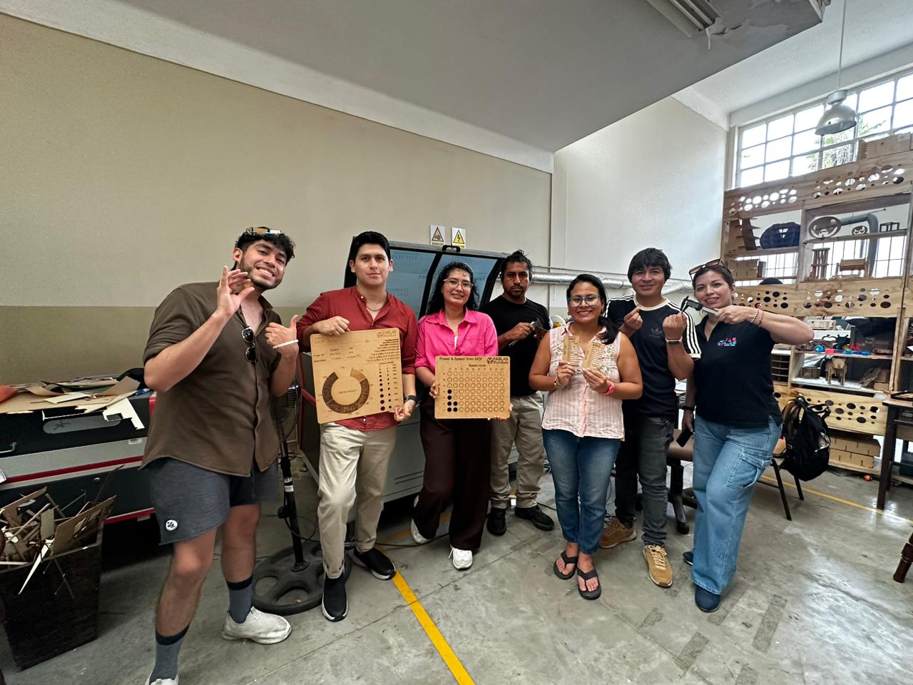
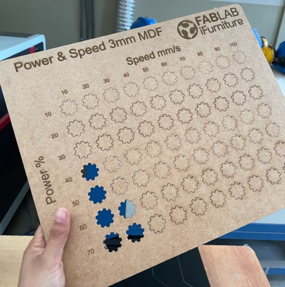
In the group project we met at the ifortunity fablab where my teammates and I did laser cutting tests. The first thing we did was select a design for the
cutting tests, taking into account the power and cutting speed. For this, we used a table that our partner Cristian had to later in RDWord be able to set
the power and speed of each shape. After that we saw the model of the laser cutter, we saw that we had to calibrate the laser cutter and in which we used
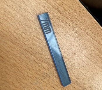
a 7 mm strip of acrylic to be able to calibrate the laser to the work table in which after being well calibrated we proceeded to send our file to make the
cut first we made the first line the first row of our test then the second realizing that we still do not He made no cut the third
fourth, with 40% power and 10% speed, the cut was made, then the fifth line with 50% power and 10% speed was already developed. The cut was developed, I saw that
from 40 speed onwards it was no longer possible. I made the cut with these selected figures, now I will do other tests but with squares to be able to check if these gear shapes have an impact on the cut.
Feb. 10
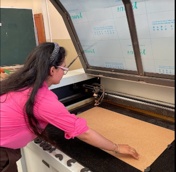
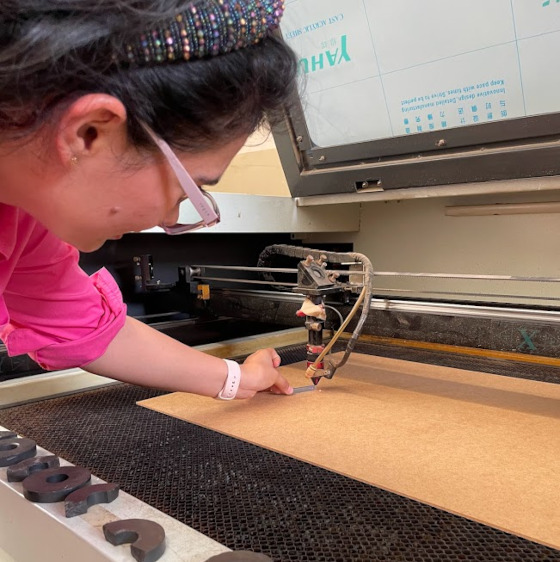
Characteristics of the C4V model 1390 laser cutter. With C02 laser tube.After reviewing the characteristics of the laser, we moved on to calibrate so that our tests are correct, then we took a 7mm rectangle that we placed between the laser and the work
table to be able to calibrate and began to move it, everything was fine when finished, and with The designs we developed began to do the tests,
first we only reached 70% power for the cut, since some in the team had experience in laser cutting and told us that probably more of it could burn, after making the cutting table ,
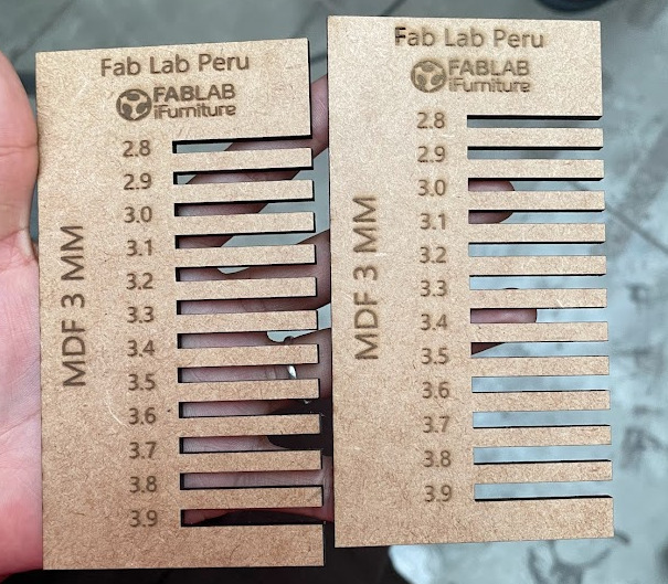
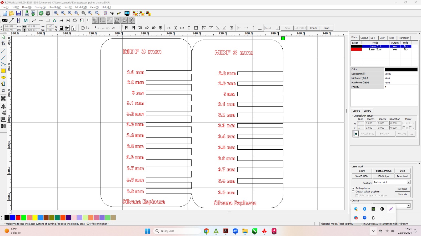
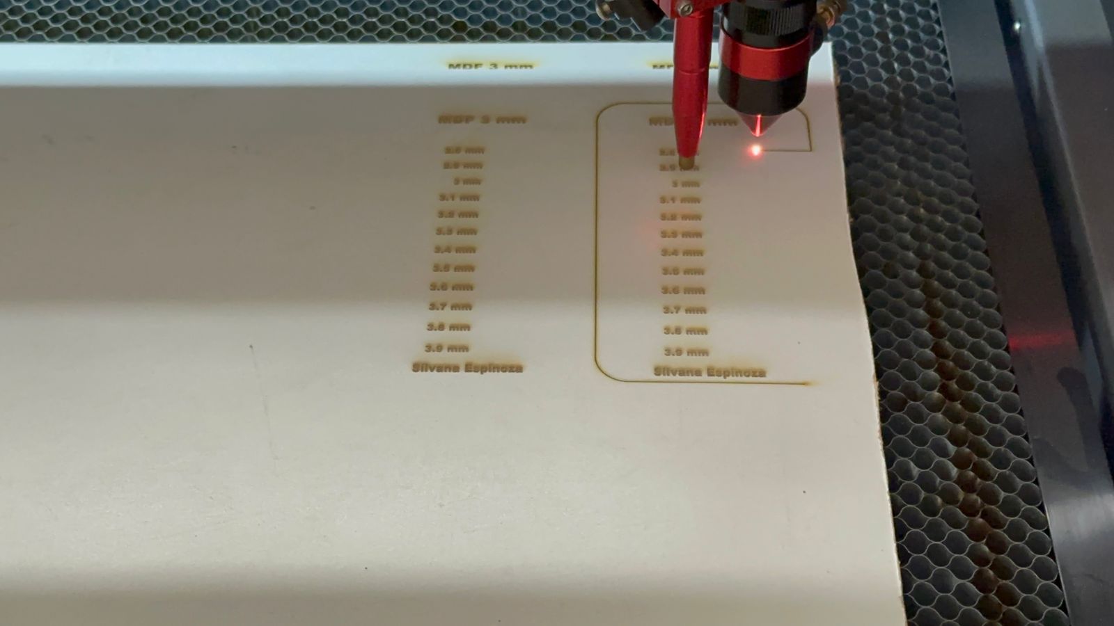
I had designed a measuring comb to see the laces and what measurement was correct.
Our file was designed by our colleague Cristian, who made an interesting shape for the tests,
then our instructor Luis told us that we should try square shapes for cutting to see differences
or compare the speed in complex shapes than in straight shapes.
That means I'll do it again.
Today I had a review by my instructors from the fable Peru in which they advised me to make the cutting board again in which my instructor Luis told me that it would be better to do it in square shapes since in the gear shape it could be that because of the curved shapes that have varying speed and power,
so he gave me his website so I could review the files he used for his cutting to guide me. In my designs I am going to make the cuts again in 3 mm MDF, also laser engraved in acrylic and I am going to test the comb again since, as I had mentioned before, I did it straight and now I am going to test the comb with the tips edged
Investigation
What is the kerf and how does it help me calculate the assemblies?
kerf as the amount of material that is removed during a subtractive manufacturing process. The thickness of the laser beam, the diameter of the cutter on a router or the width of the teeth on a saw blade can serve as a reference to observe the term in practice.
But what about a CNC laser cutter? Unlike a CNC Router, laser cutters do not allow you to select internal or external paths, all the cutting is done “on” the line as a center, this is very important because in the weeks that follow you will see a lot of difference.
You have to consider the material that you will use in the laser because you will need to measure the thickness of your beam and compensate for that measurement in your design program so that the drawing includes in its dimensions the correct additional fraction of a millimeter.
Have a vernier caliper on hand so you can accurately measure the thickness of the material you will use to cut, it is important to make the sample with each type of material you have.
Laser cut design and Cutting result
With my group we designed a comb file, our instructors recommended us to make several of all the types of materials that we found, we took the measurement of the thickness of the material and we increased and reduced the thickness by 0.1 mm until we had eleven divisions. With a material labeled as 6 mm the range of dimensions should go from 5.5 mm to 6.5 mm, if it is 3m the range goes from 2.5 mm to 3.5 mm.
Testing a laser machine is important to ensure that it is operating correctly and that the settings are appropriate for the specific material and job.
Power and Speed Adjustment: Determine the optimum power and speed settings for the specific material you are using. our first group task.
Verify Focus: Ensure the laser is focused properly for accurate cutting and engraving.
Engraving Tests: Perform engraving tests on different materials to evaluate quality and adjust settings as needed.
Verify Accuracy: Perform cutting tests on precise patterns to evaluate machine accuracy.
Calibrate the laser machine
Basic Calibration of a Laser Cutter:
Laser Focus Adjustment:
Make sure the work table is level.
Adjust the height of the table or laser to achieve optimum focus on the work material.
Checking and Adjusting Mirrors
Verify that the mirrors are clean and properly aligned.
Use a laser marker or laser pointer to ensure that the beam is properly reflected from each mirror to the cutting head.
Cutting Head Alignment
Align the cutting head so that it is perpendicular to the work surface.
Adjust any misalignment to ensure accurate cuts.
Power and Speed Calibration
Perform cutting tests on reference materials to adjust power and speed according to your needs and material type.
7mm gauge to use as a reference for laser cutting machine.
Placing the 7mm gauge between the laser and the cutting table
Correctly arranging the MDF cutting material so that all sides
Test design
I will make some designs in various 3D design software in order to see what the results look like.
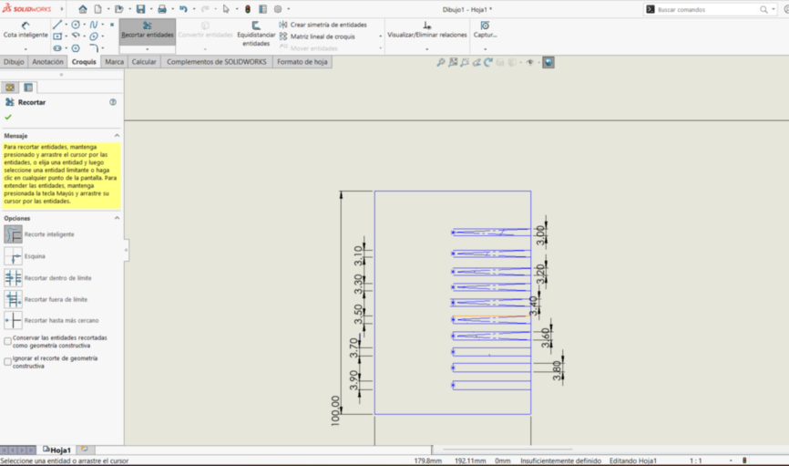
Use SolidWorks to design the fitting test. Making sure to model the dimensions and geometries according to what I saw as a reference that our instructors sent us.
Export the model to a format that the laser cutter can understand. DXF (Drawing Exchange Format) or DWG (AutoCAD Drawing) formats.
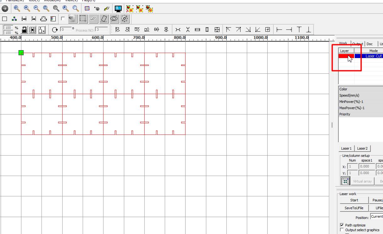
Open the DXF file in your RDwork laser cutter control software and configure cutting options such as speed, power, and laser settings.
Perform cutting tests using MDF and Cardboard.
You can use small pieces to check cutting accuracy and machine settings.
I designed in solidwork the comb from scratch, I took the reference measurements that my partners indicated to me.
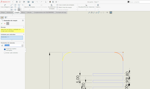
I reconde the tips to have a better fit, that after doing the first test and we realized that it was necessary.
The settings and the cutting power is important, for that we first made the test table.
Here I started another test with the comb with borders, more beautiful, it has the same measurements that I did with my colleagues at the FAb Academy.
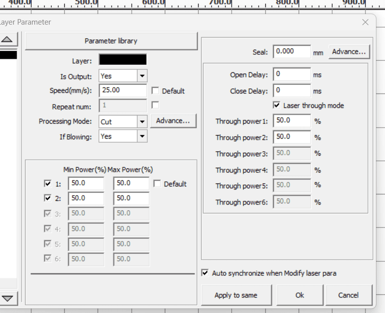
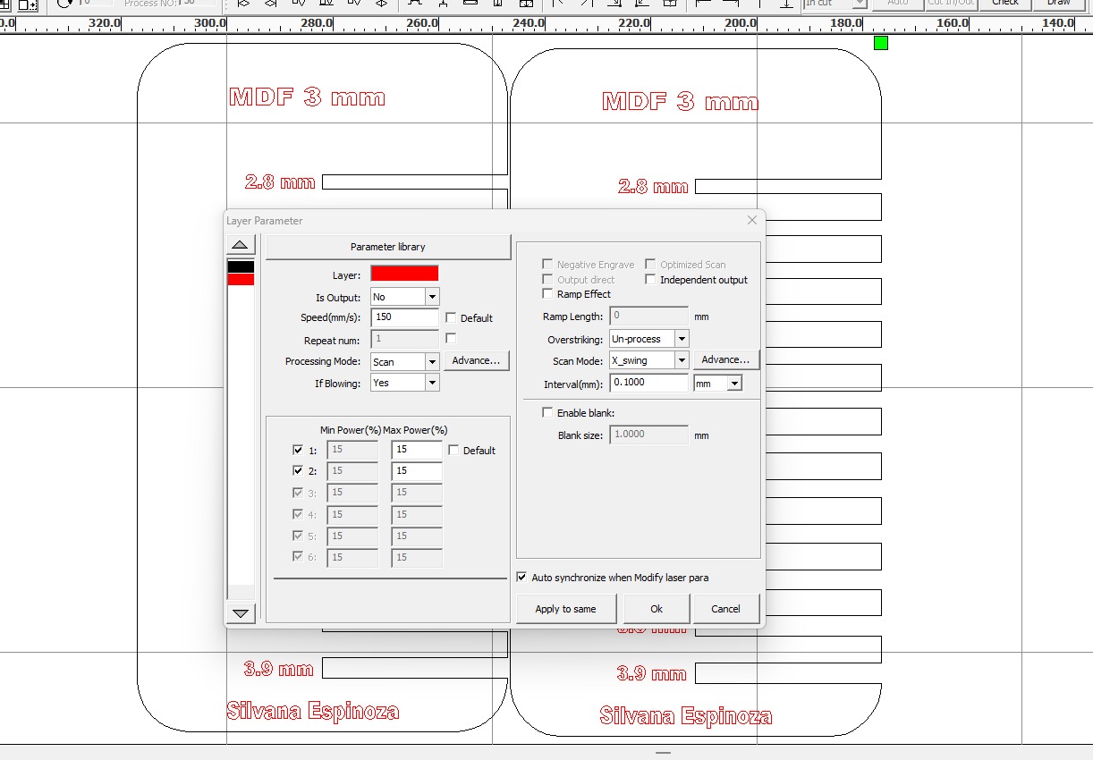
We configure the engraving parameters first, with a speed of 150mm/s and power of 15%
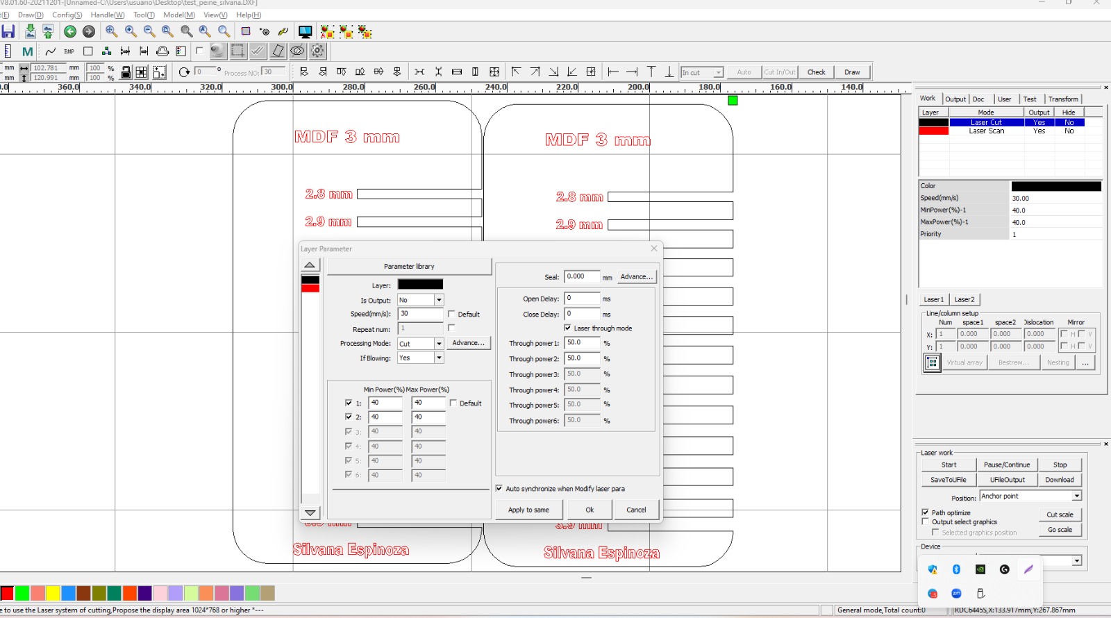
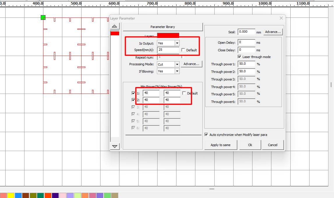
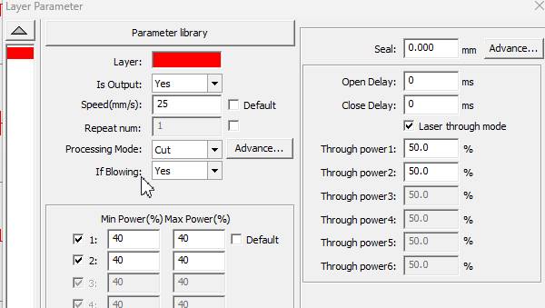
We configure the cutting parameters at speed 30mm/s and the power at 40%, remember that in processing mode it must be in cut
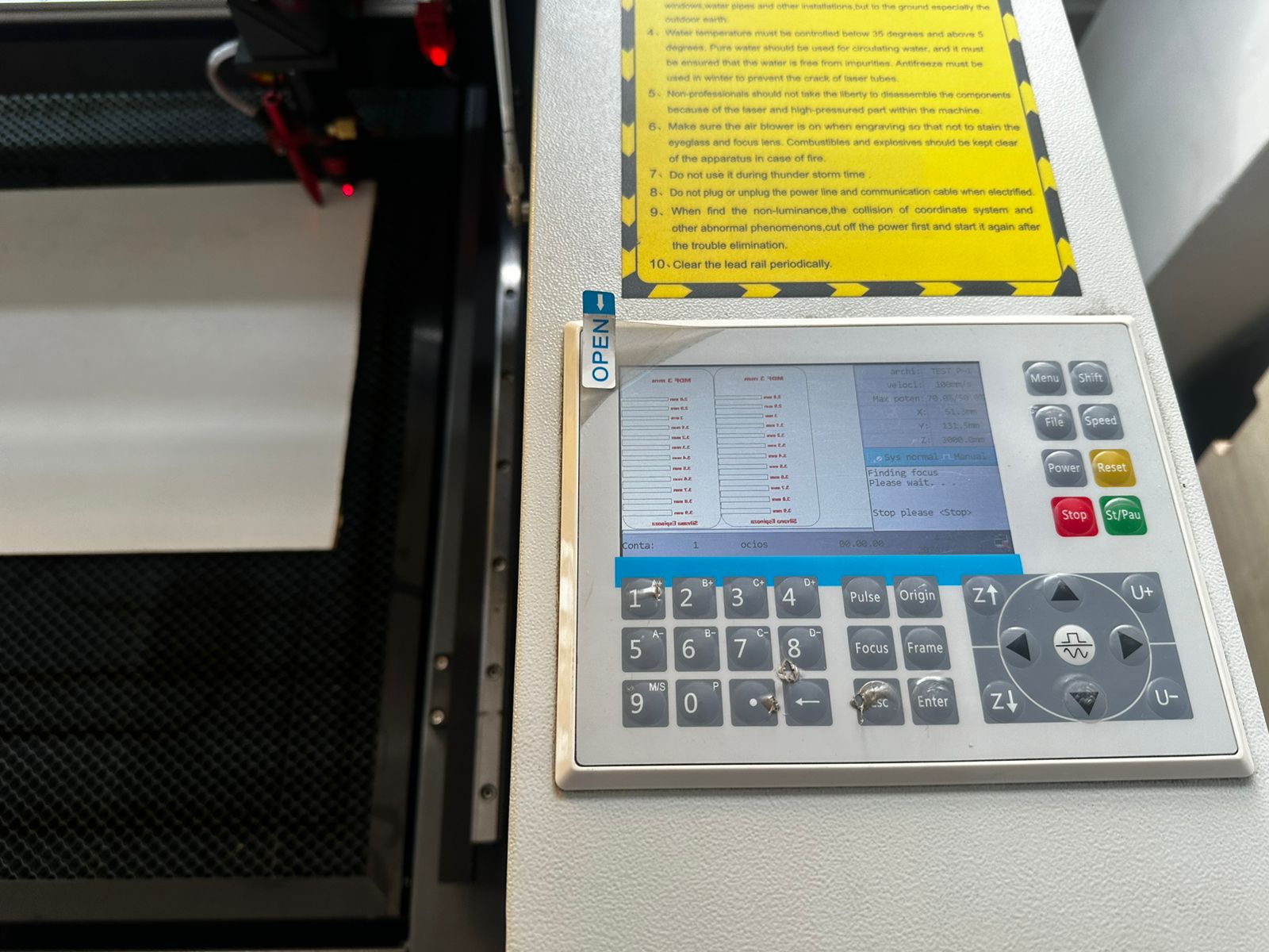
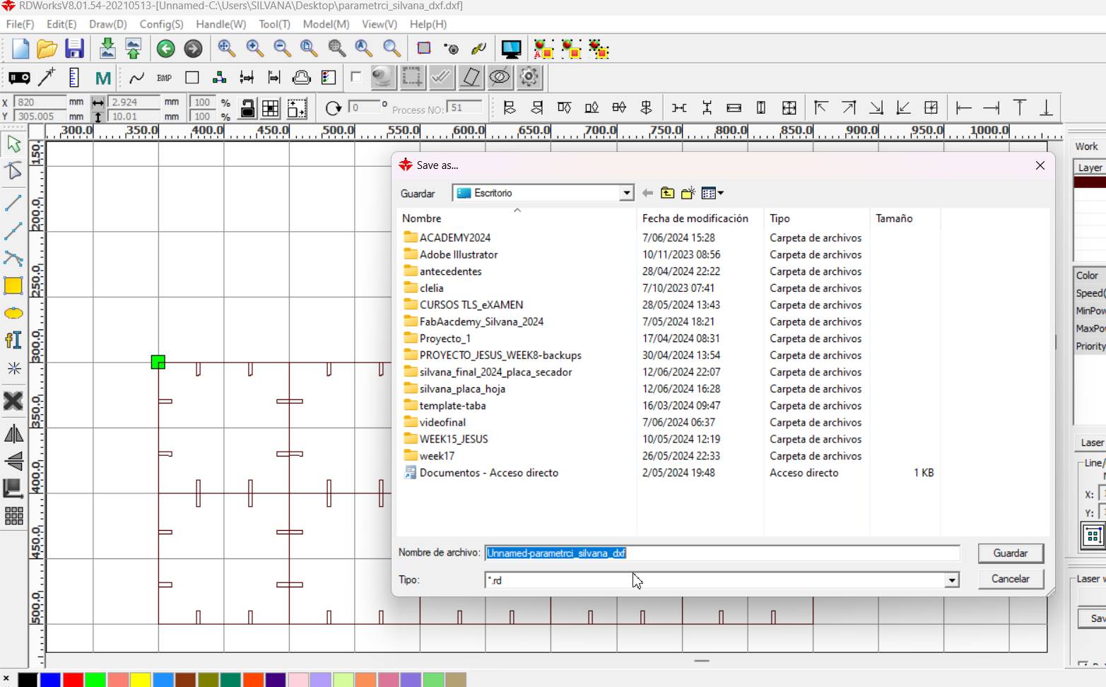
We save it on a USB, we take it to the laser cutter and copy the file that was saved in .rd
First the engraving is done and then the cutting is done, it is pure intuition since remember that if you cut first the pieces could move, so, first you engrave and then cut.
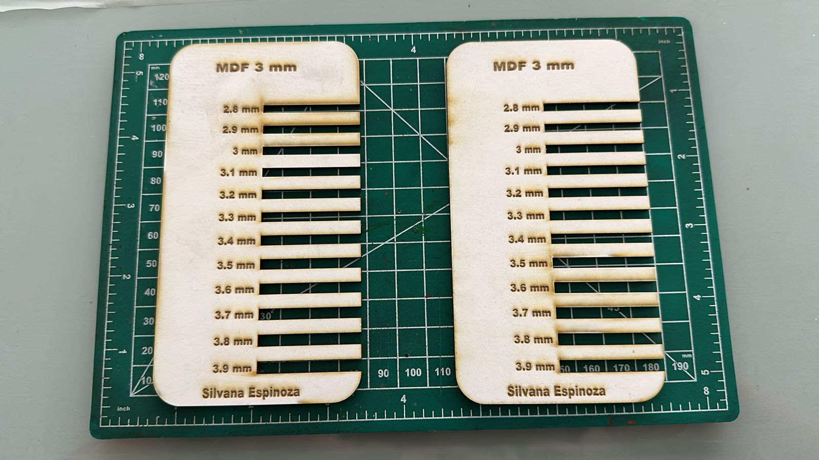
This was the result, it turned out very well for my first tests.
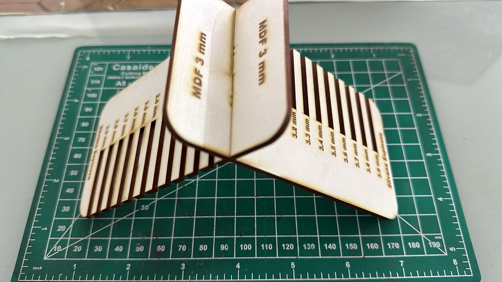
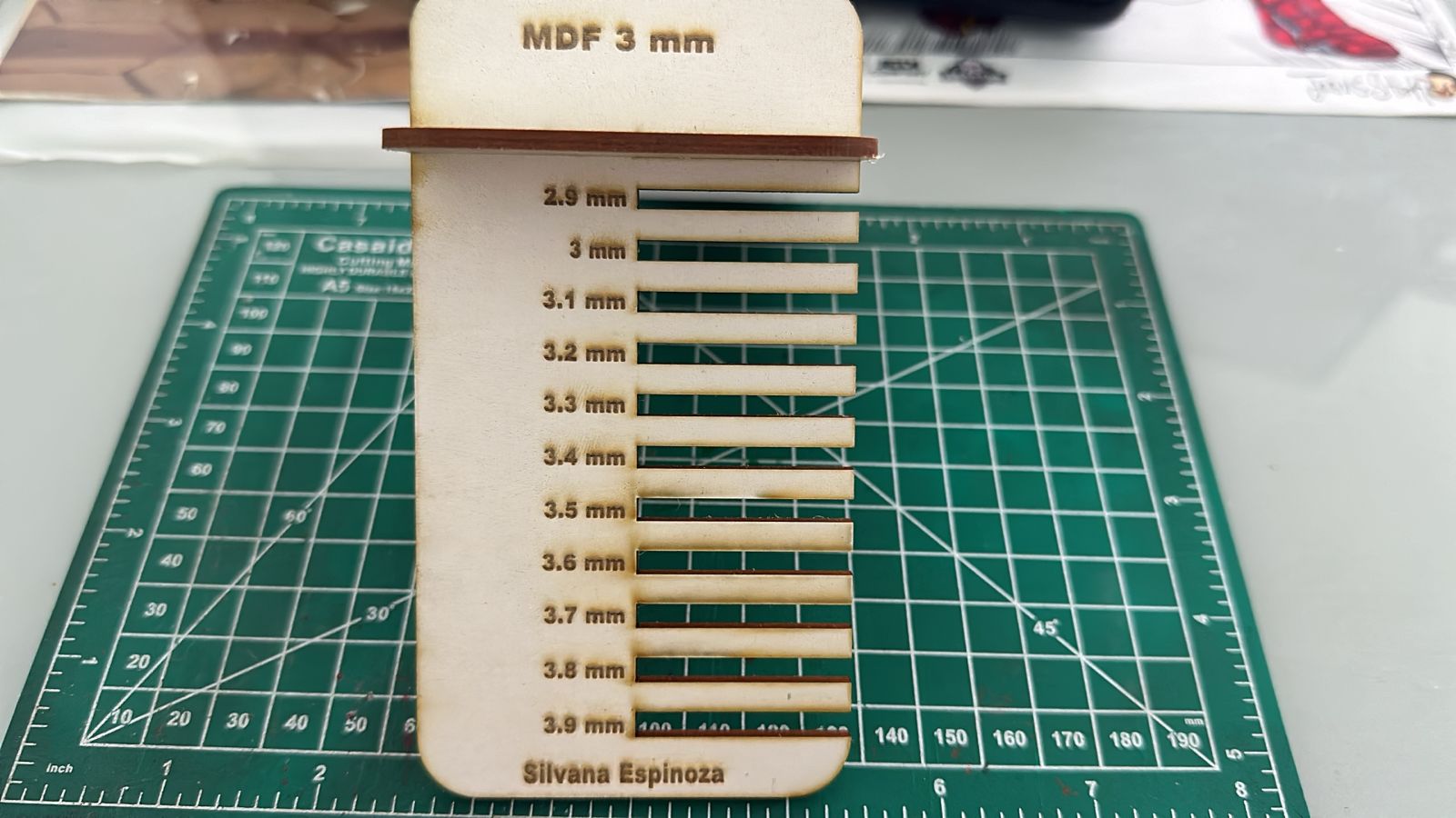
Here seeing the fit of the pieces
I realized that I need it to be very tight so I can make my set of pieces to place decorative objects in it.
You save it in .rd on your USB, here I show you why I think I mentioned it but I didn't put a photo. I hope it helps you understand this laser cutting and engraving process.
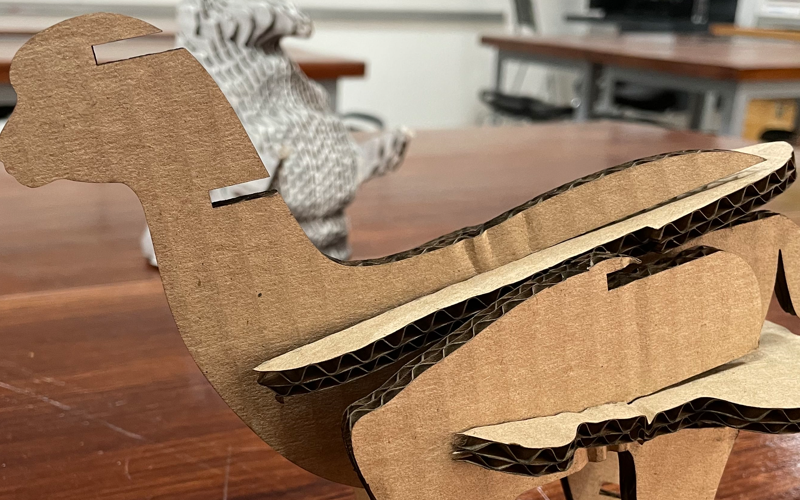
Try my llama
Here I did something that they don't let us do because of how easy it is, but I want to show you a quick way to be able to make interlocking pieces for any design you want.
It's only 5 steps
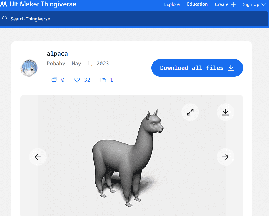
First you find a design that you like in stl or obj, look for it to have some characteristics, such as a wide and not so thin shape,
you download it it has to be easy to cut into layers and that you love!
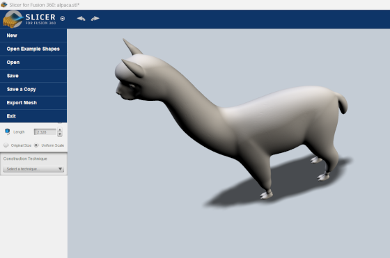
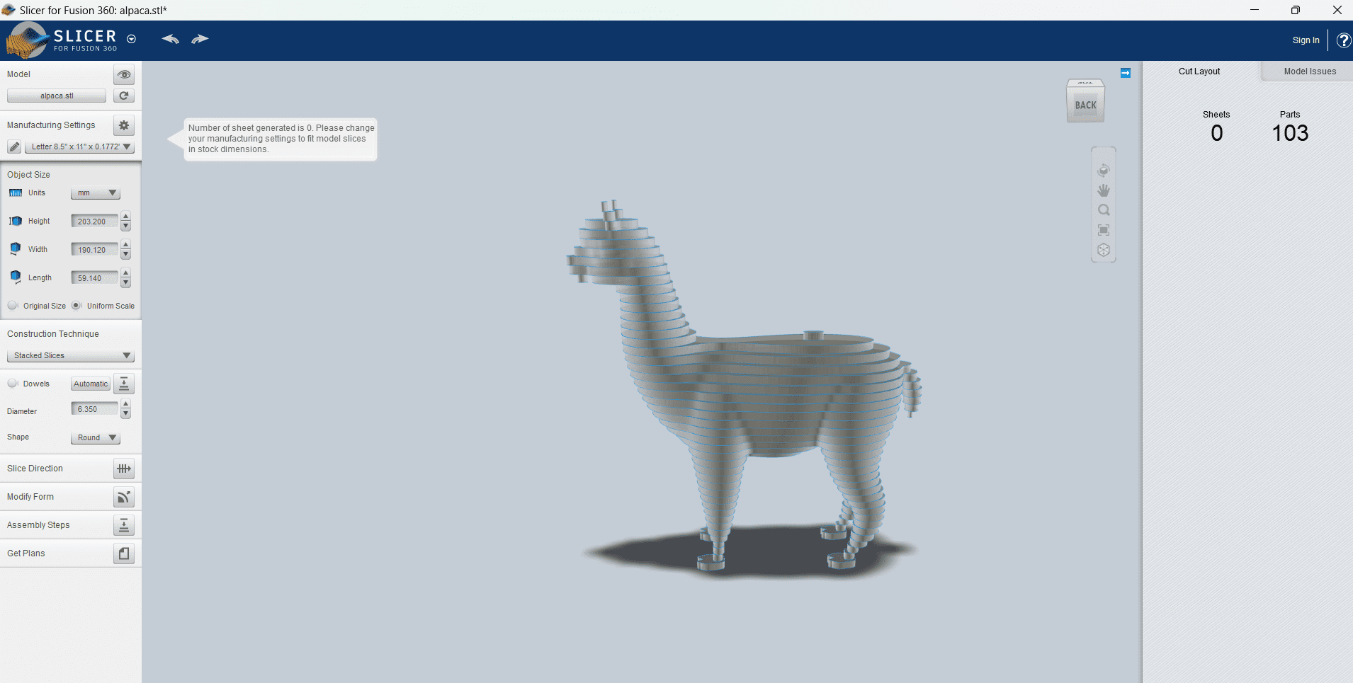
Here I placed the stl design in the fusion 360 slicer and began to explore its work area, the truth is that it is easy but you must have judgment and know what structure and what function your piece will have
Now you are going to download the Slicer Fusion 360, this is where you can make the cuts. You play a little with the pieces, the amount you need and the angle at which you want them to fit.
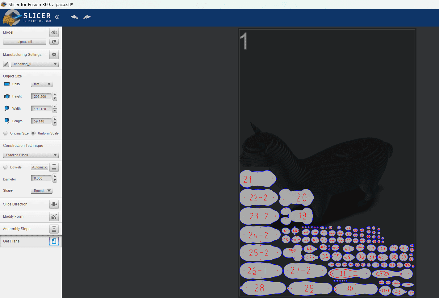
Here I made the view of the pieces, to see how it would be assembled and how many pieces
there would be, here I continued testing the smallest number of pieces to assemble my llama.
Here I practically already had the plans ready to laser cut.
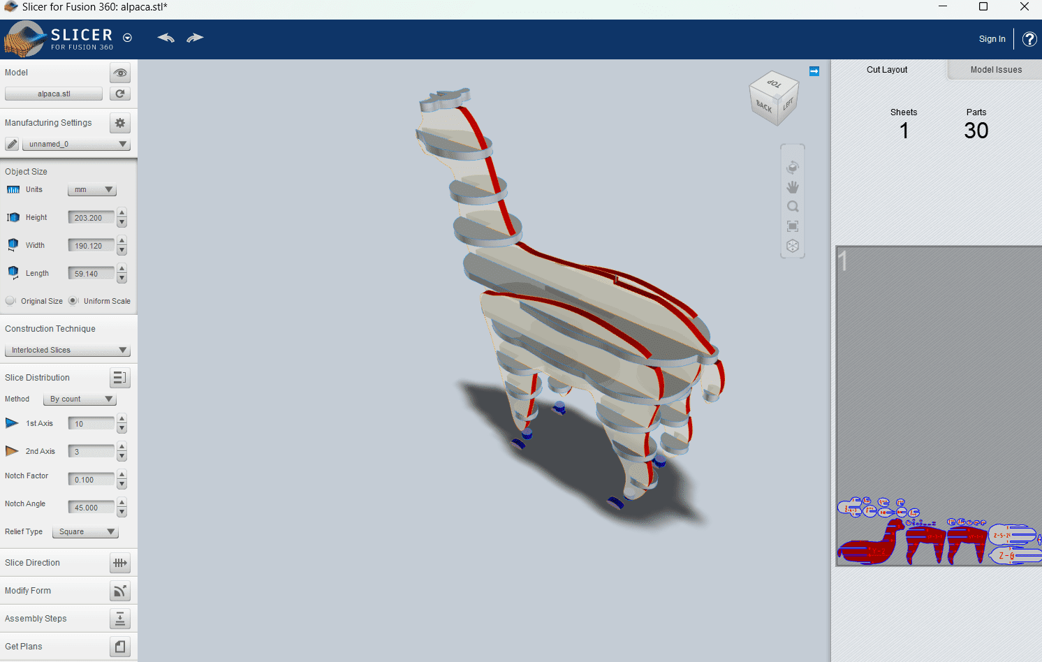
Here we can see the end of the amount of pieces that I decided that my llama should have,
I thought about making a shelf for pots for my succulents, I loved the design and how easy it was to do it.
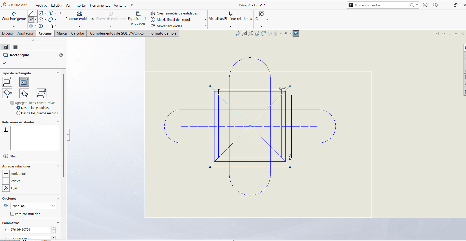
Now it's time to make my parametric construction kits, I started experimenting with Solidwork in which it became easier for me because I had learned it the previous week and I really liked the workspace.
Solidworks
This was the first design that I achieved in solidworks, it was a challenge because it was the first time I used it to make pieces that can fit, it was a challenge but it was not the one I chose to make my parametric kits,
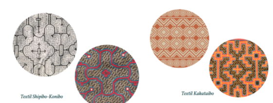
I wanted to be inspired by the textile of the Shipibos of Pucallpa, and at the beginning it came out wrong I was insisting with the program because I felt that I had no way, and with some youtube videos
I managed to make the shape that I imagined and it came out better than I expected and I love it.
I tried trying to replicate the figures of Shipibo art, I started with a central square so that from there it can take shape.
Here, by eliminating all the strokes, I was left with the shape that I liked in the upper parts but it took me a lot of time, which is why I thought about exploring another program for my design.
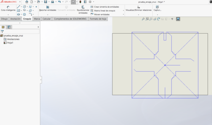
Here we can see how I did not finish my parametric piece in Solidworks, it was difficult for me to understand it and so I decided to switch to fusion 360 to be able to design my parametric kits.
I still place the file I made here, with the intention of being able to achieve my parametric design, here I will not place any cutting file since it was not achieved, only the program file so that the design attempt can be observed.
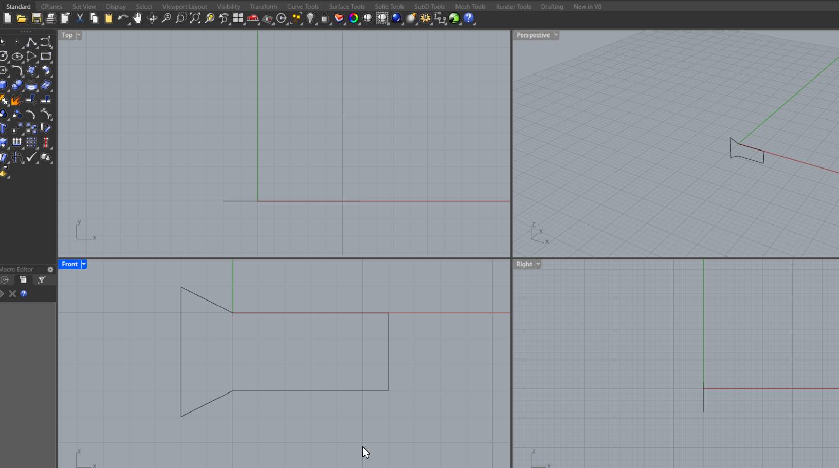
After doing parametric design tests in solidworks and fusion 360 and not having the desired results, I went to Rhino.
At first it was complicated because it was the first time I was experimenting with this software.
I spent a whole day trying to understand each algorithm until I achieved it and I was able to make my first nestable piece.
I managed to do it and have a 3 mm space to fit which I was seeing to be correct with the cutting tests I did previously.
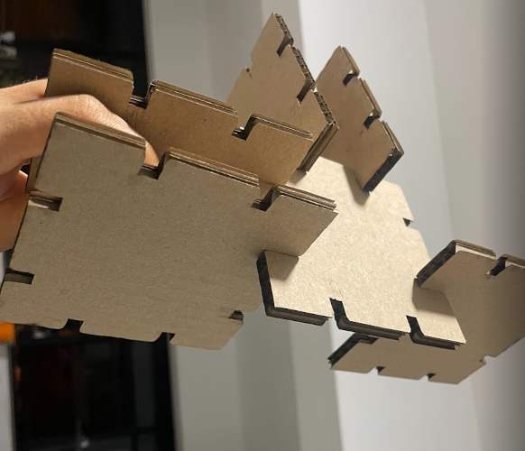
I started by drawing the size and thickness of the lace on my piece.
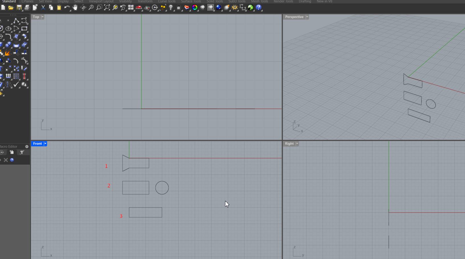
I saw different types of ways for the lace to be made.
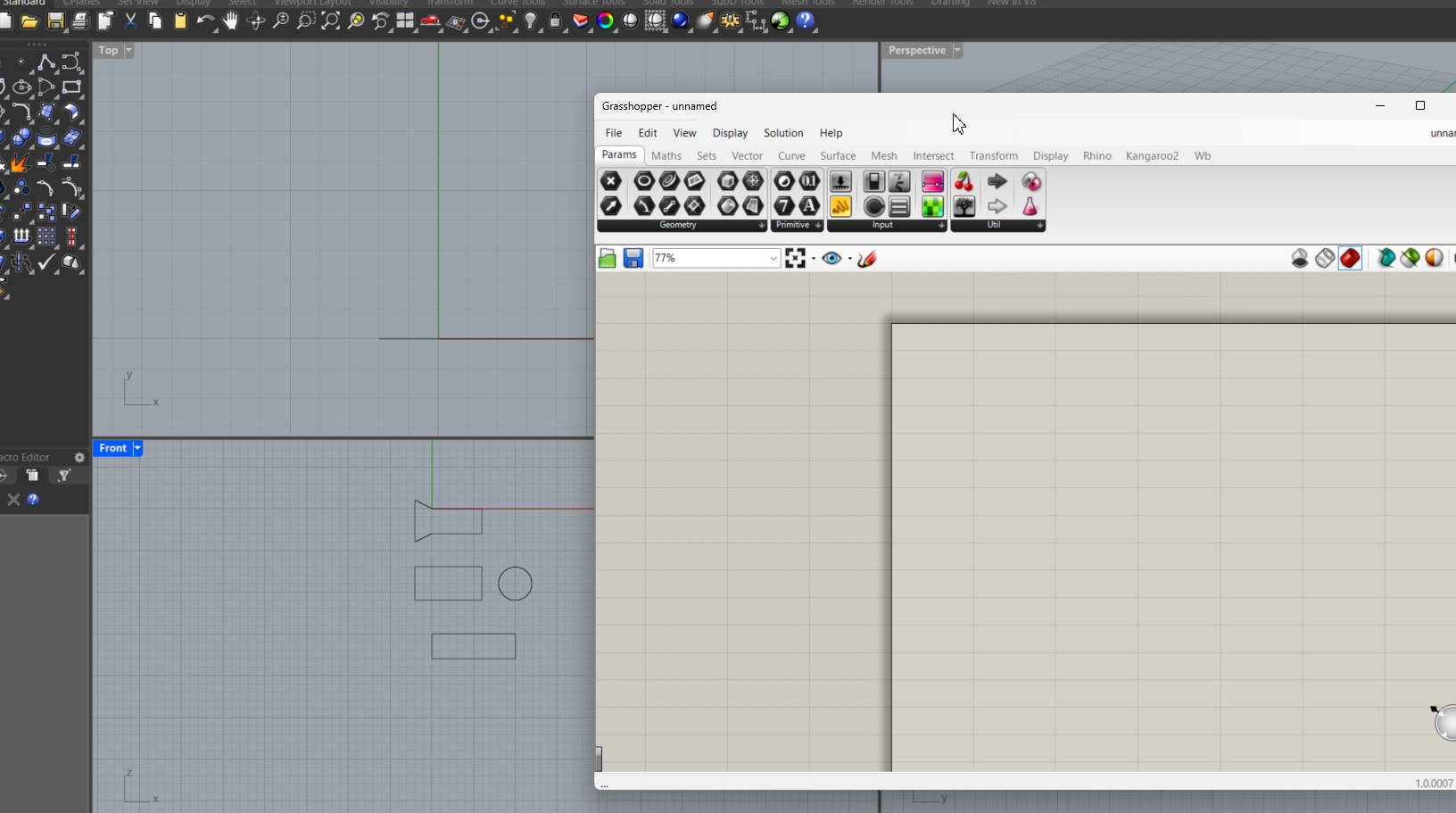
Once done, I opened grasshoper to start with the parametric design.
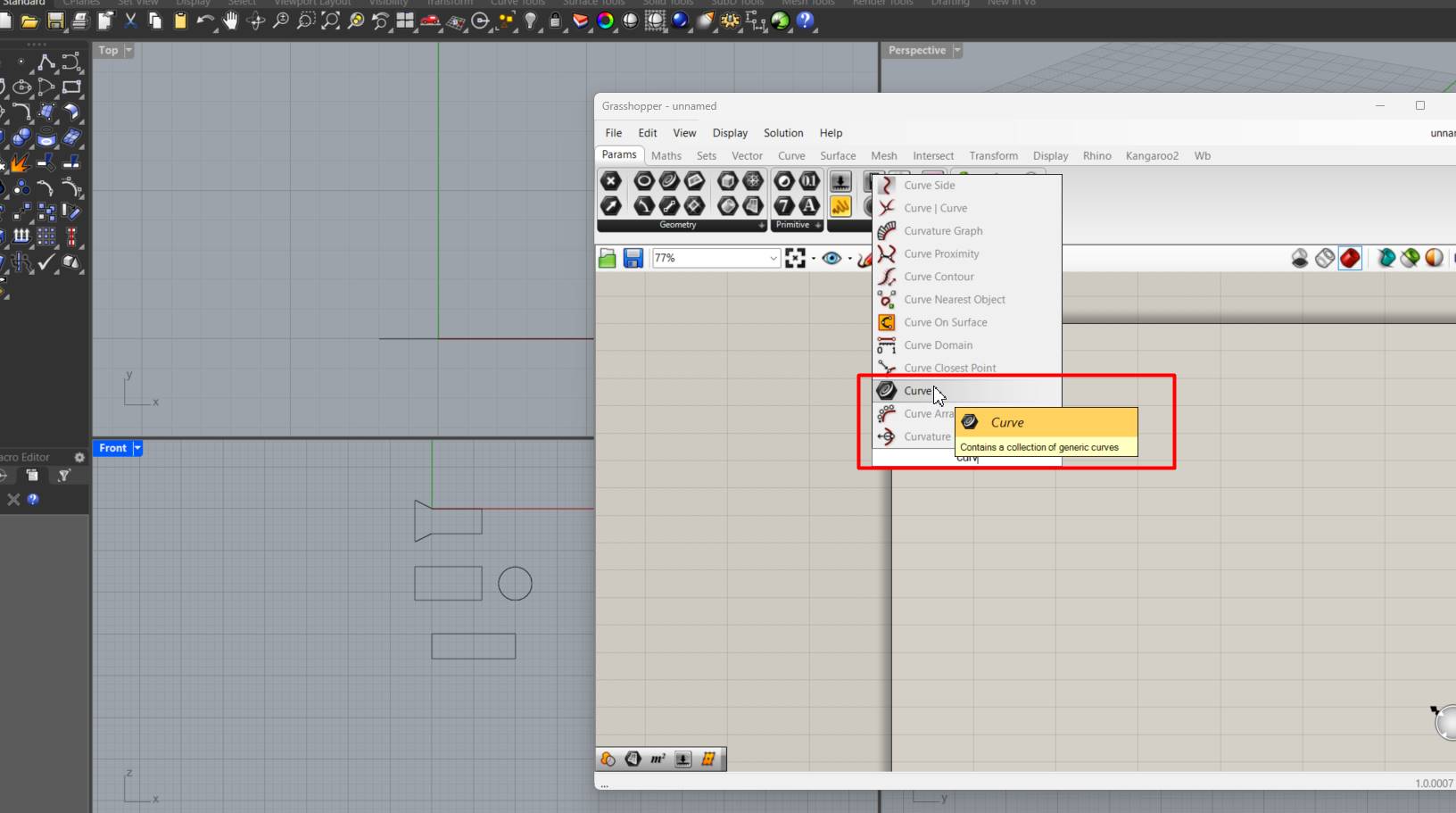
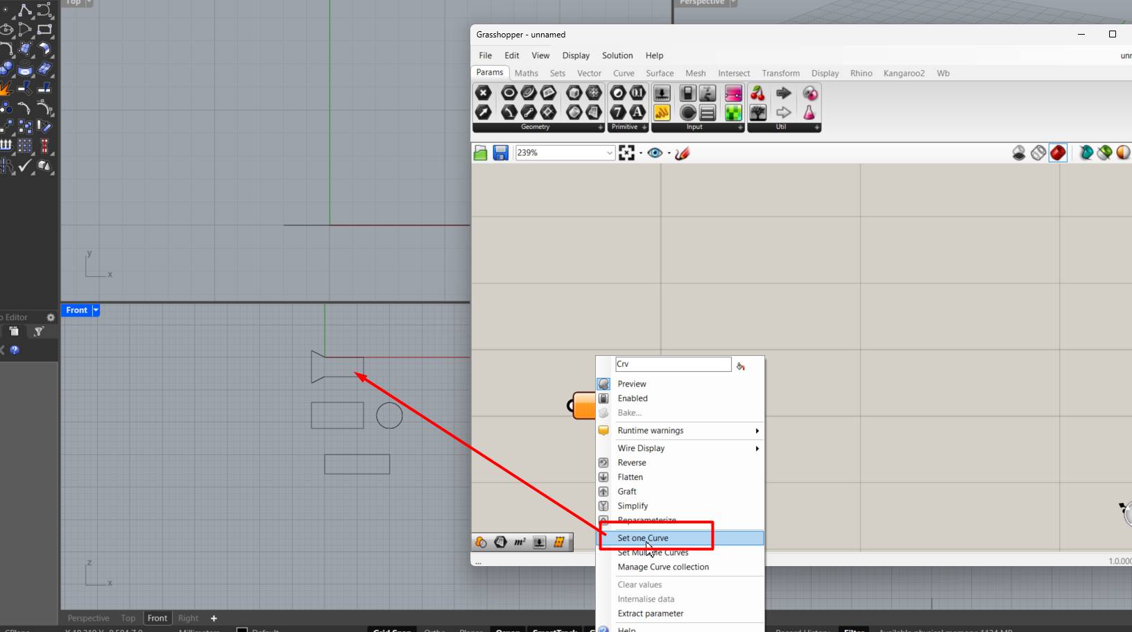
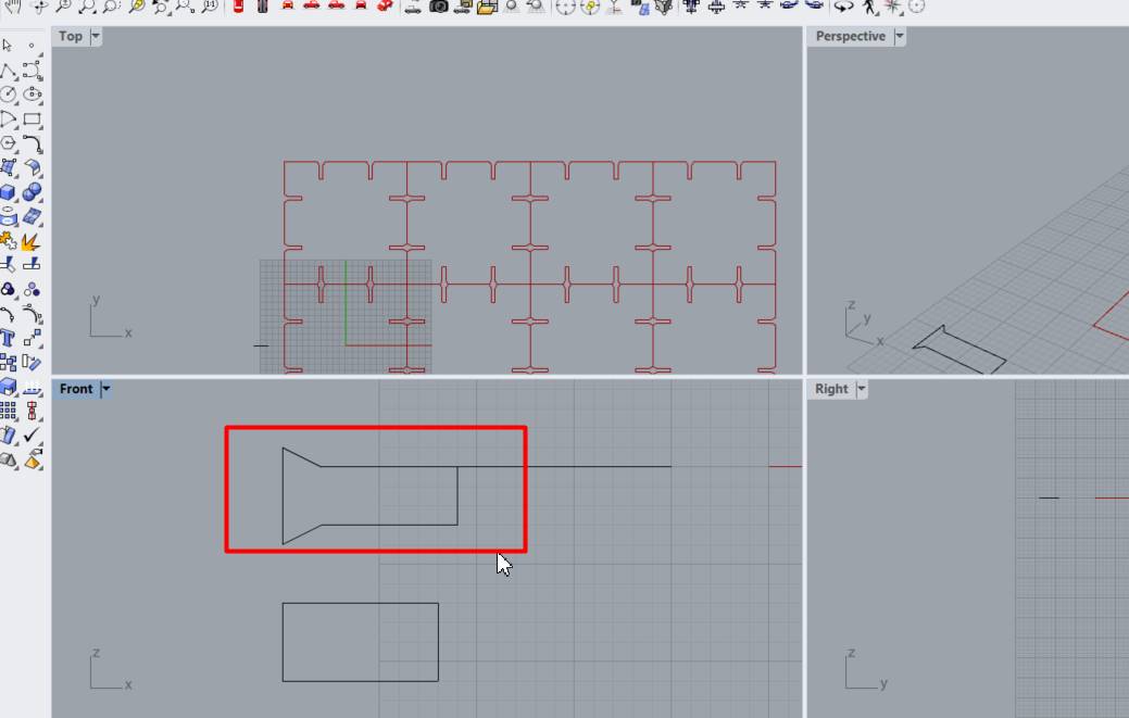
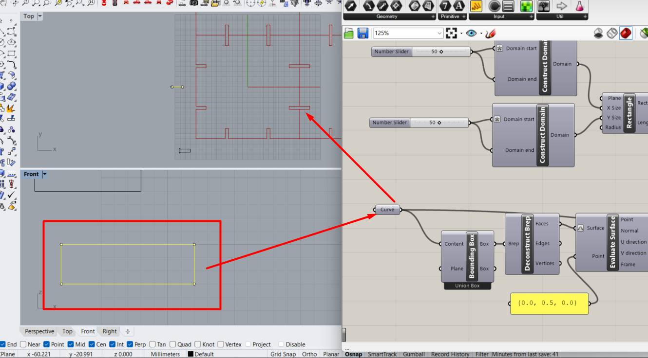
The first thing I placed was a Curve to be able to make the connection with the shape I want the lace to be made.
Here we can see that I related it to the way I wanted so that we can start programming.
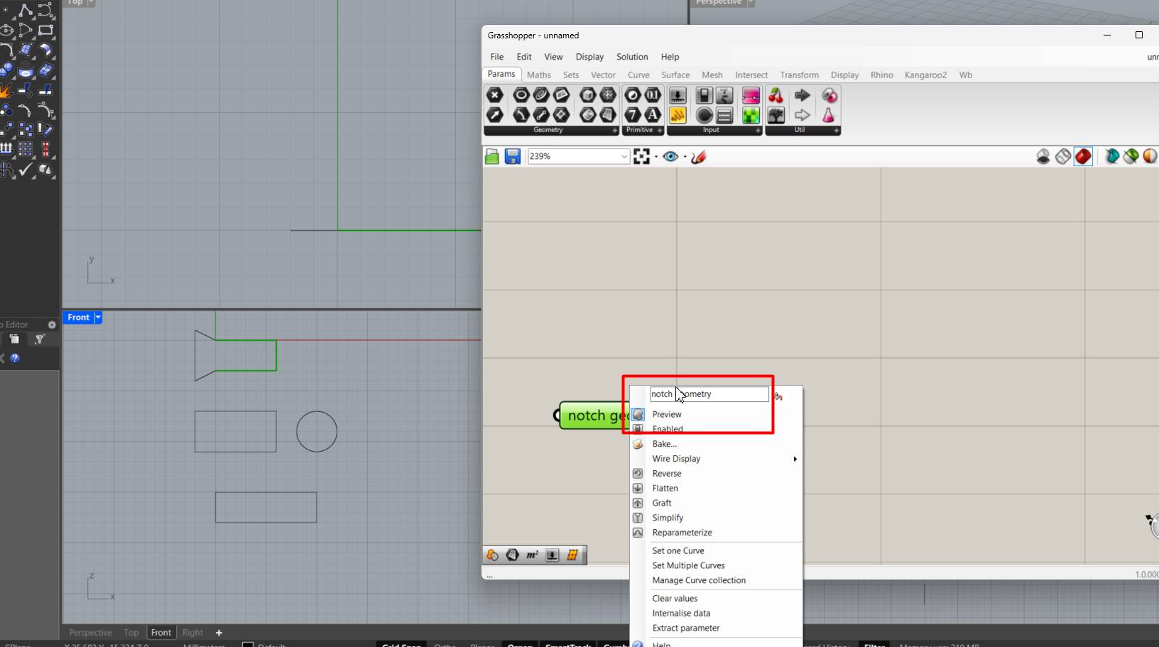
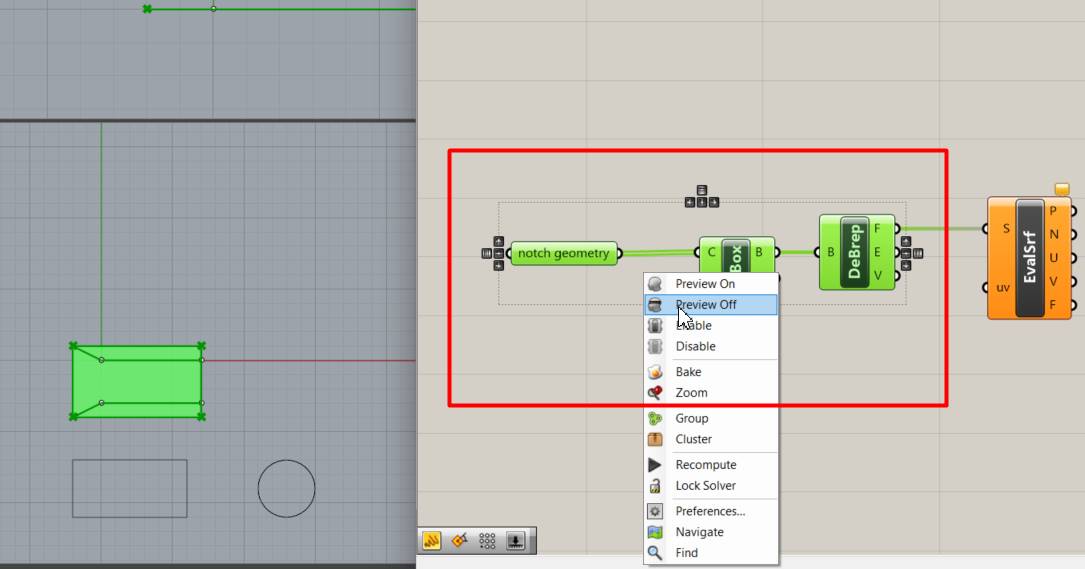
I changed the name when we are working on the notch geometry.
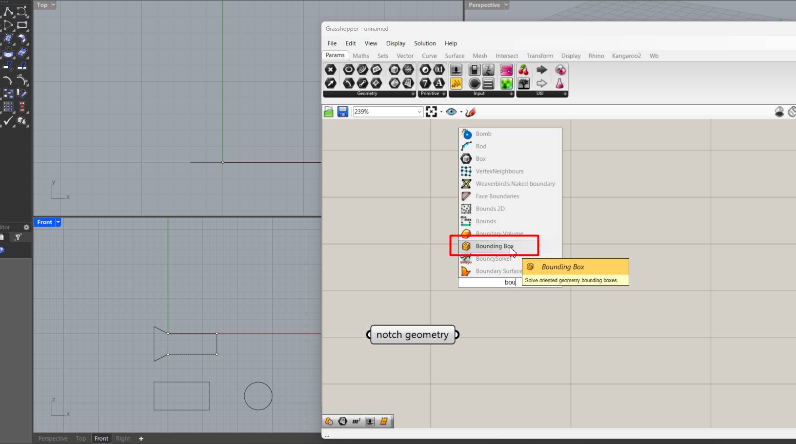
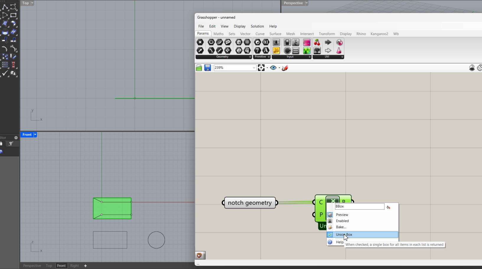
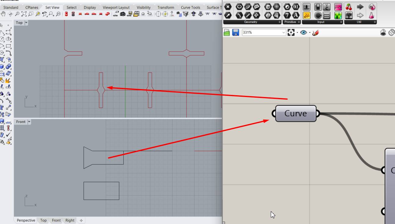
We started by building a box to store the gemoetry in a box.
Once we have it, we right click and "union box"
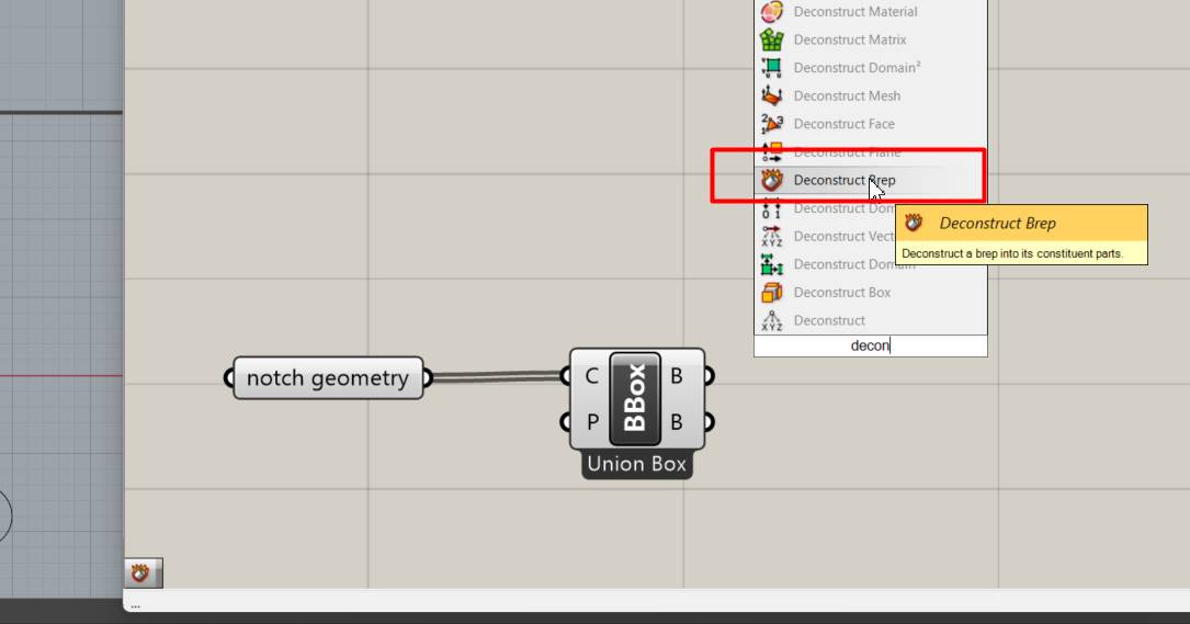
Here we are going to look for Deconstruct Brep to be able to deconstruct some parts we join our BBOX with DeBrep.
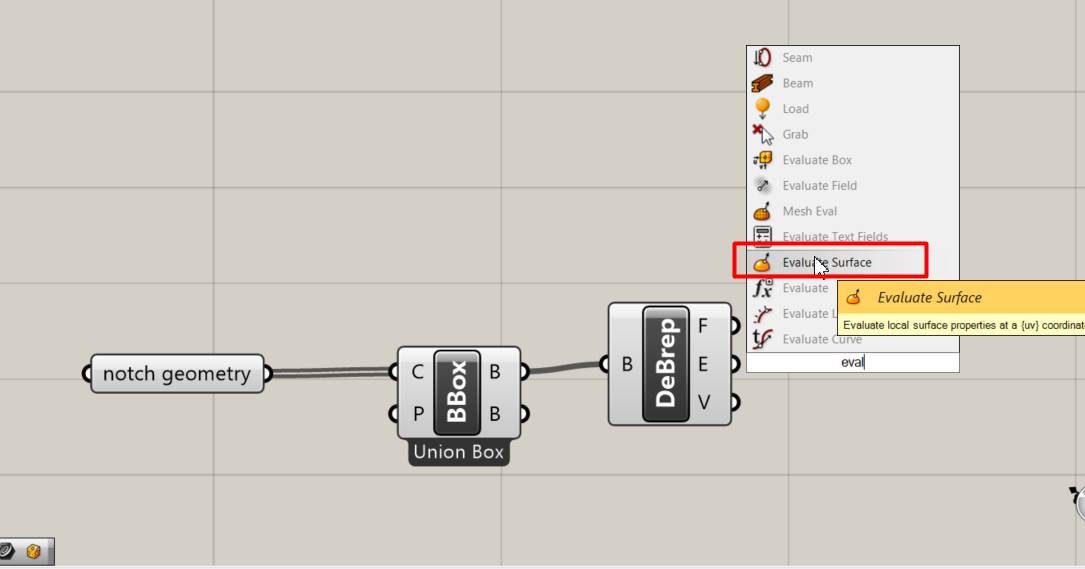
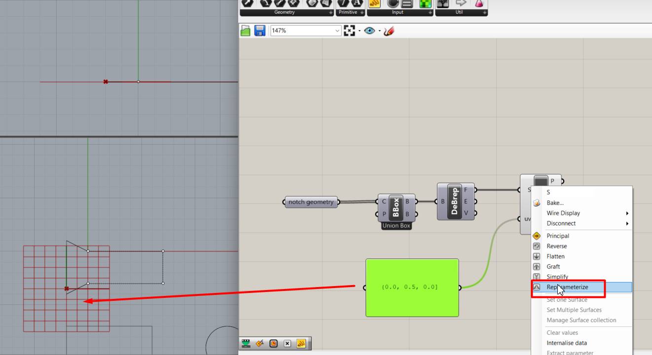
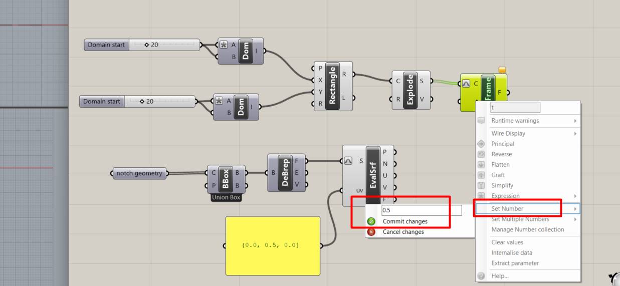
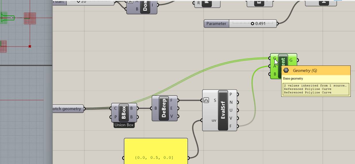
We place the Evaluate Surface to be able to evaluate where it is or coordinates.
We proceed to pay with the "Preview off", this is so that some parts of the process are not seen, and your progress is not seen dirty, only the desired result is seen.
Evaluate a surface at a given point. It allows you to determine the location of a point on a surface and provides information about its coordinates, curvature, normal direction, and other associated attributes.
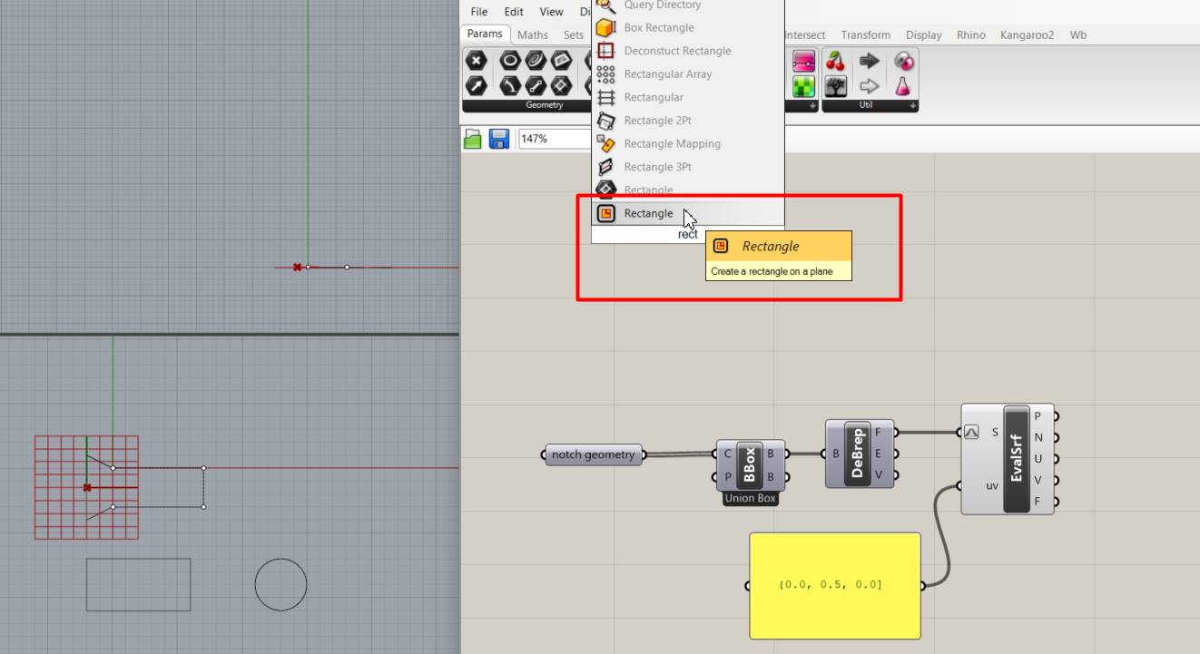
Here I go a little higher and add Rectangle to create a rectangle in the Rhino plane.
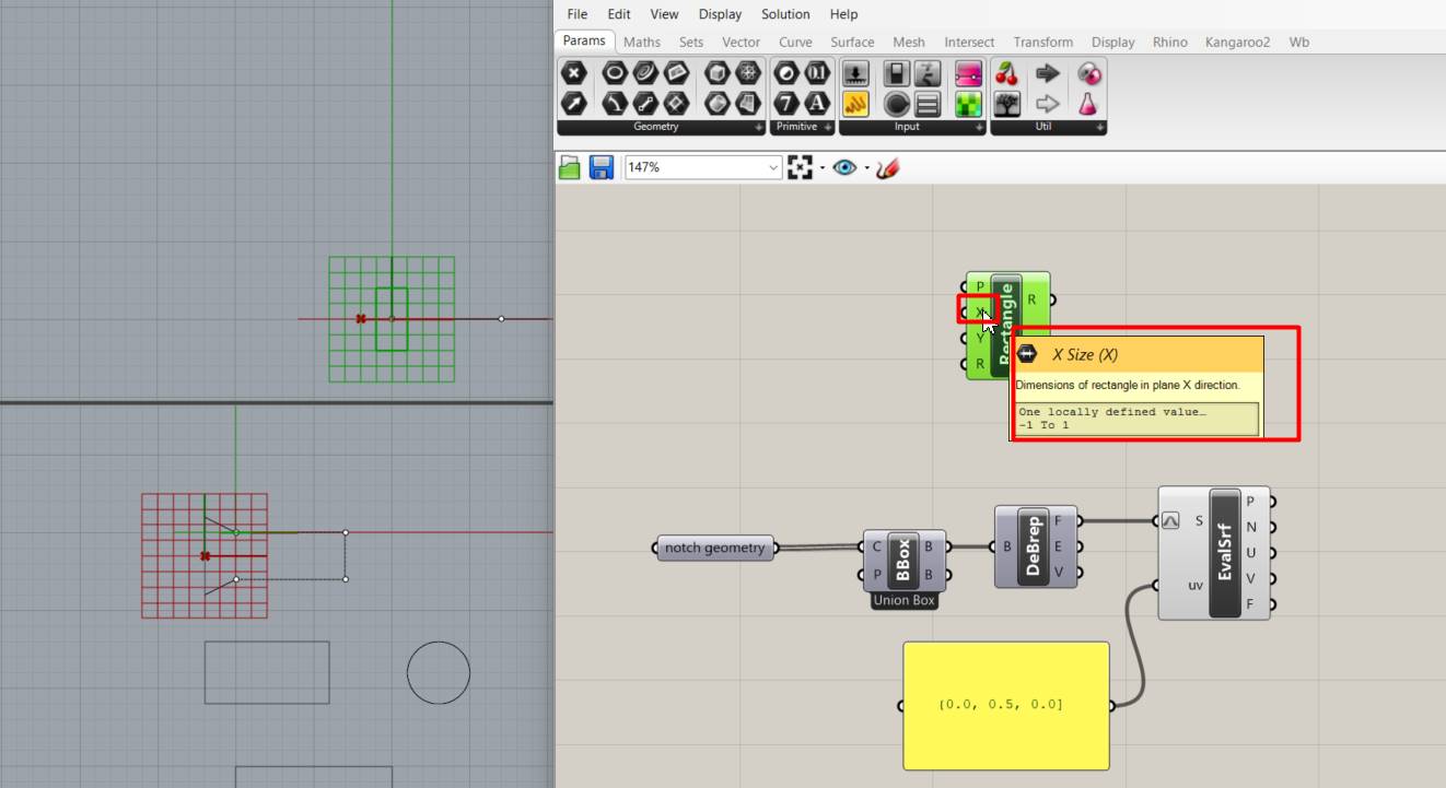
Now we place the dimension of the rectangle in the X plane.
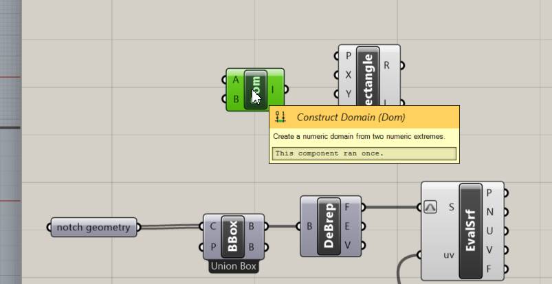
We put construct Domain, we create a numeric domain that defines a range of values. This domain can be a range of integers, real numbers, or even a custom sequence of values.
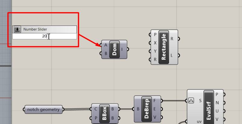
The "Number Slider" is one of the basic components in Grasshopper that allows you to generate a numerical value within a defined range. It is a convenient way to adjust numerical parameters.
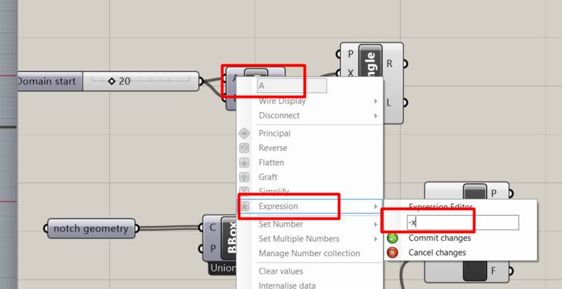
the "-x" expression in the "Construct Domain" component, you need to make sure that the Start value is greater than the End value for the expression to make sense.
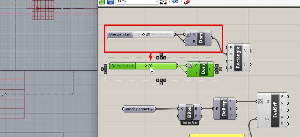
Here we duplicate so we can have two points to change on the y axis.
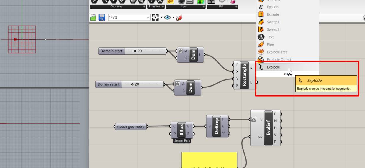
We now add Explode, allowing you to split a domain into its individual components, in this case, the start value and the end value.
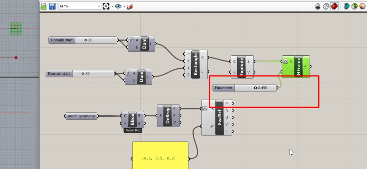
Add "Horizontal Frame" which is used to group elements visually within a horizontal frame. This is useful for organizing and presenting components more neatly in your definition.
Add a "Number Slider" component to control the size of the horizontal frame.
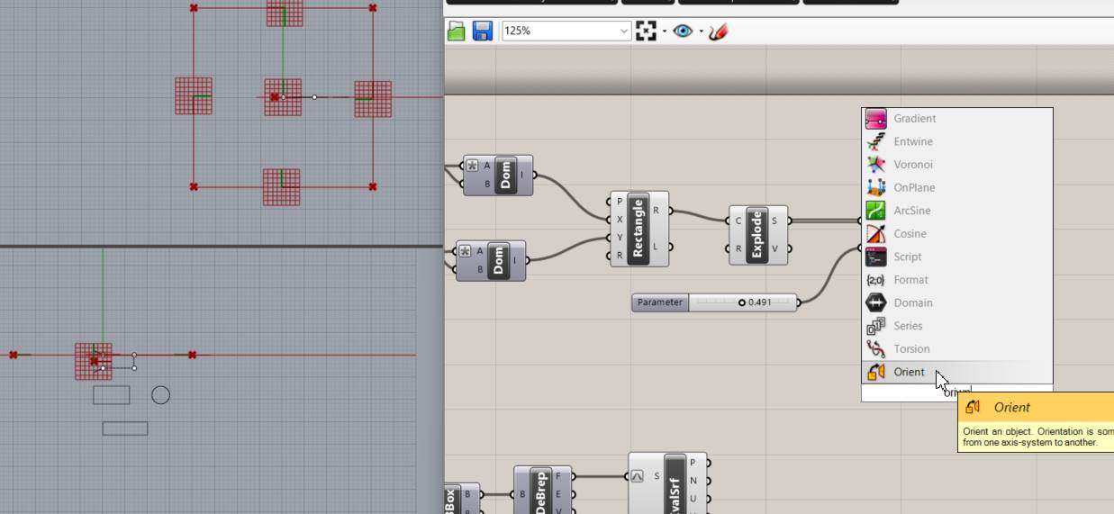
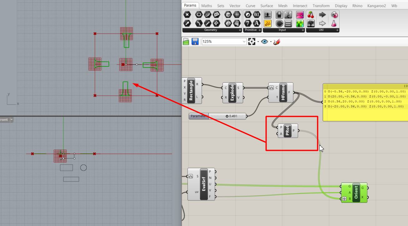
Connect the output of the "Vector 2Pt" to the "Orient" parameter of the "Horizontal Frame" component. This will set the orientation of the horizontal frame based on the vector you have defined
The "Base Geometry" component, this component will provide the base geometry that will be used as a reference
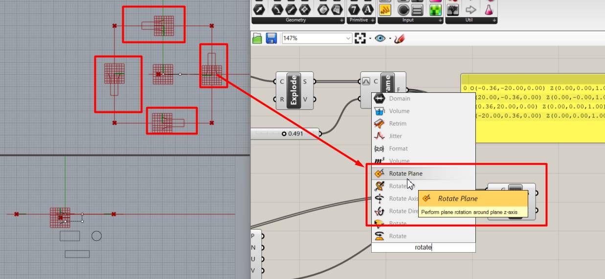
Here we can see that the sockets are placed at another angle, so we add the Rotate plane to rotate it.
It's ready and it's already taking shape for my nestable piece.
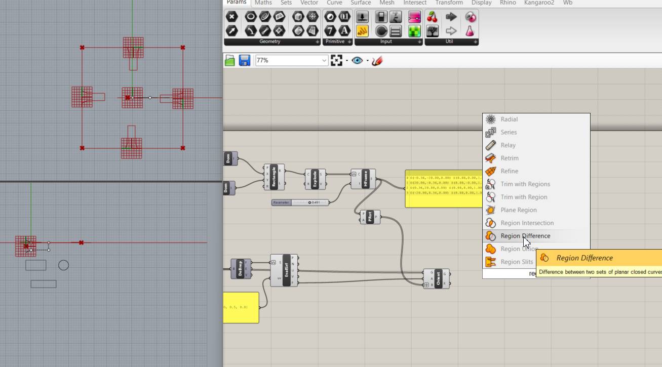
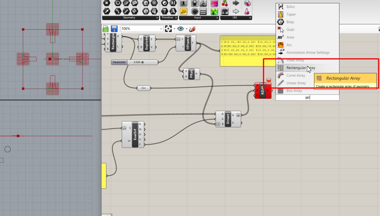
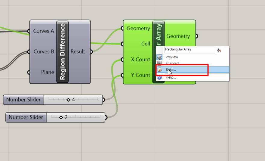
Now add Region Difference to be able to connect between 2 planes and close the curve you create
"Rectangular Array" This component is used to create a rectangular array of elements. This will cause the geometry resulting from the difference operation to be the one that will be replicated in the array.
Here we can see that it has already been formed and looks better.
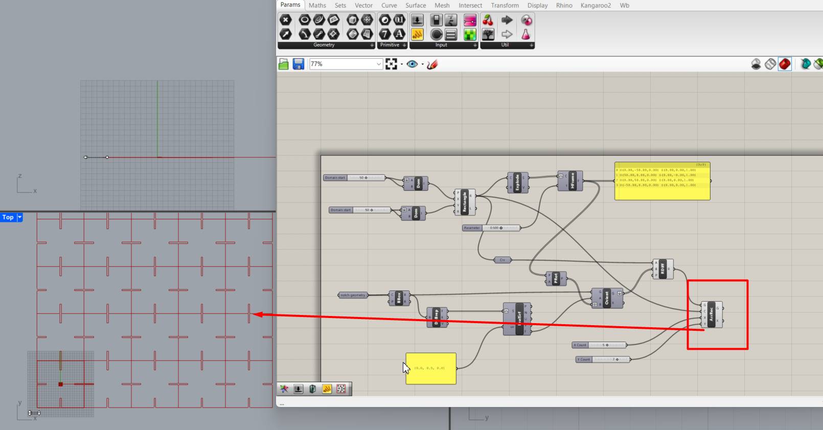
Now I have duplicated the last part where the sockets are generated and I can have two to be able to make different shapes.
Short sample of the program designed in grasshopper for the design of a modular part
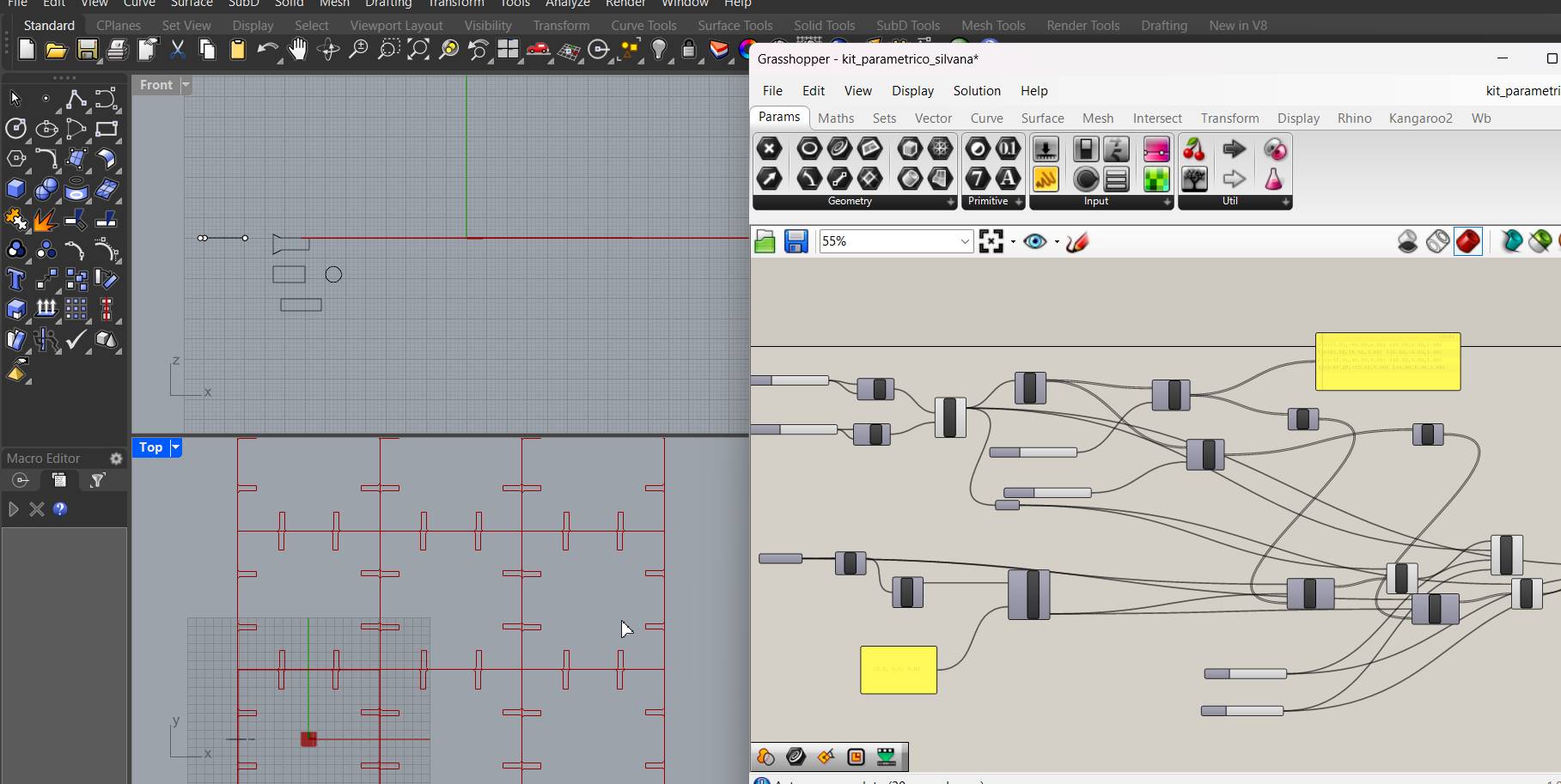
First I designed in rinho and the material I wanted to use is MDFlo of 3 mm first so my design initially had that measure, then I changed to 6mm for
the thickness of the canton I was using for my first tests, I love Grasshopper because it allows me to make changes from the algorithms and I do not have to edit each change I want to make one by one, but only change the variables and everything is adjusted to those that you indicate.
Here I try another lace model, taking into account the cutting width.
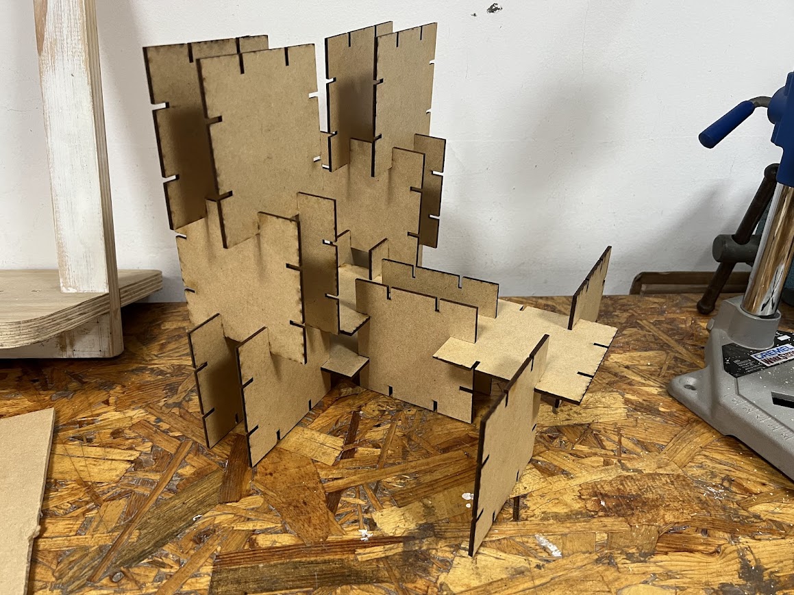
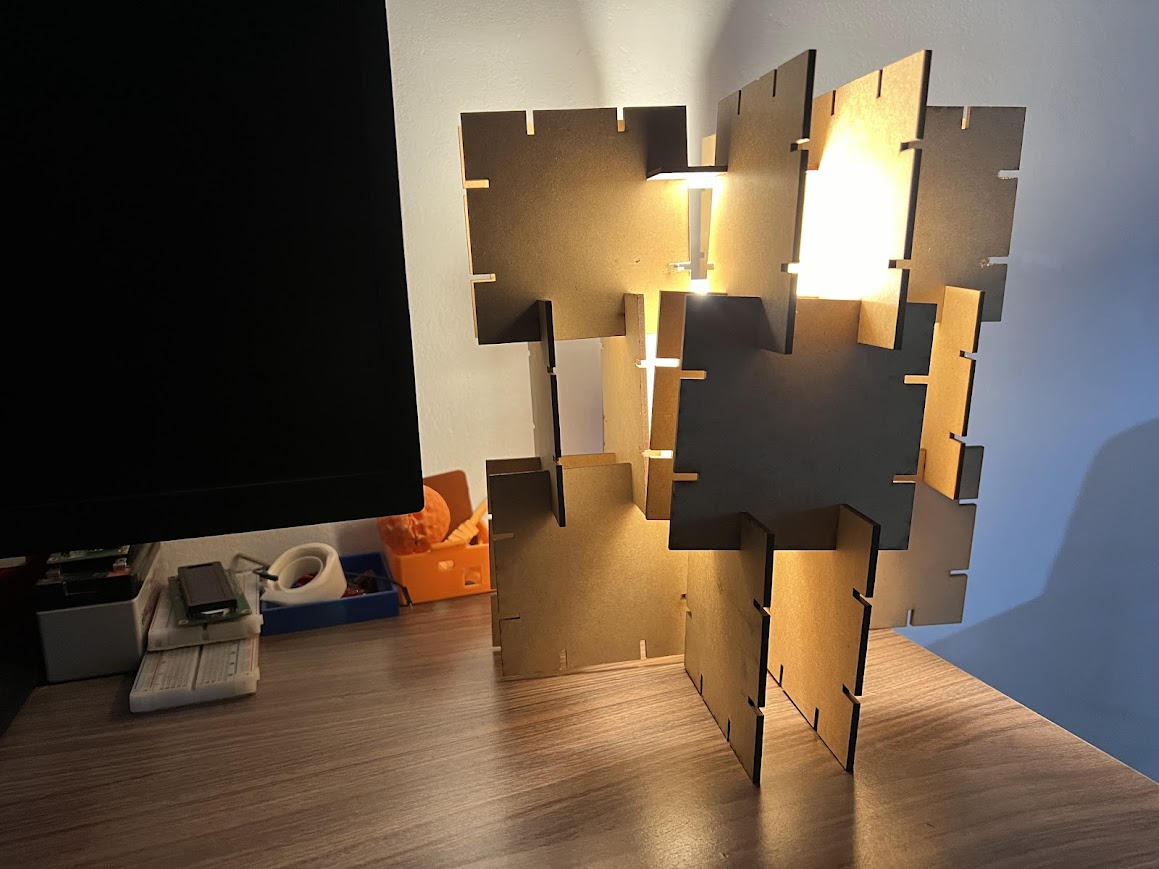
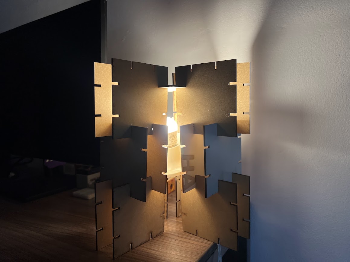
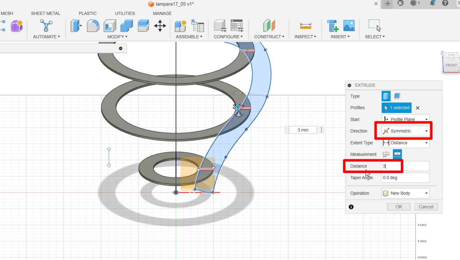
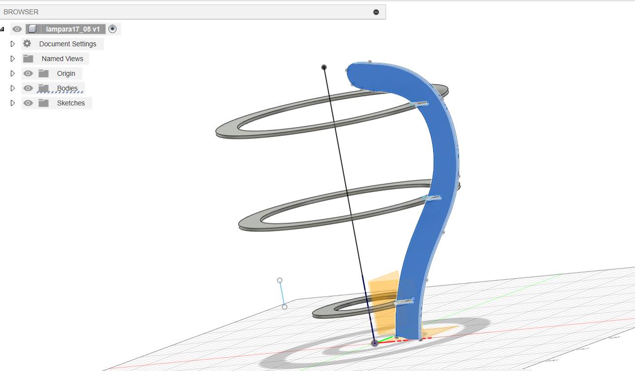
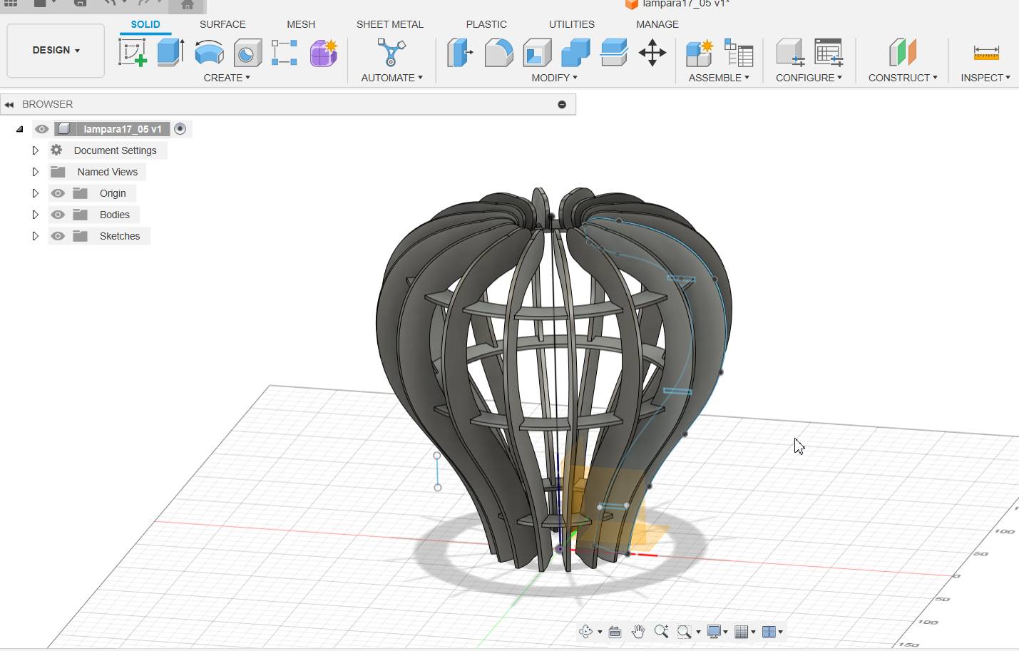
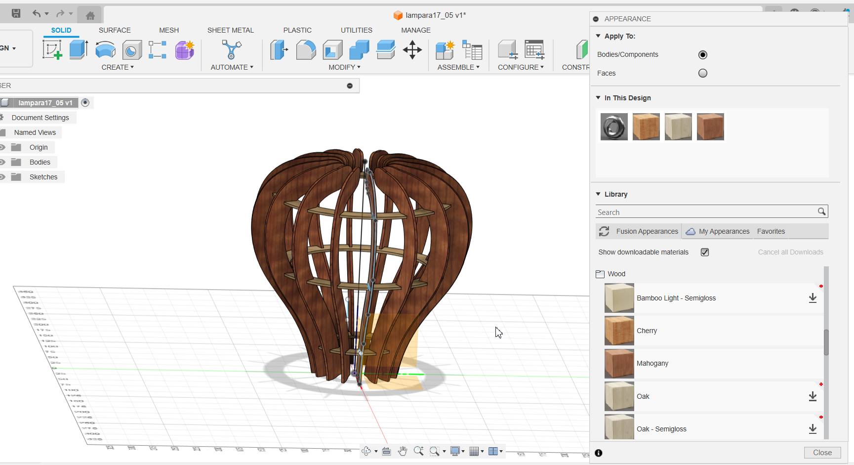
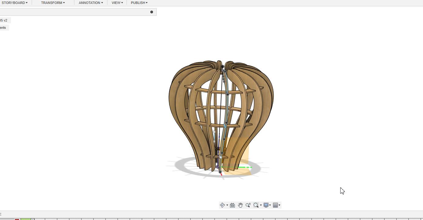
As I had mentioned, there was a 3mm design to use MDF, now we are going to make the short with MDF and make different shapes, including a lamp. It was very fun and I felt like a real product designer.
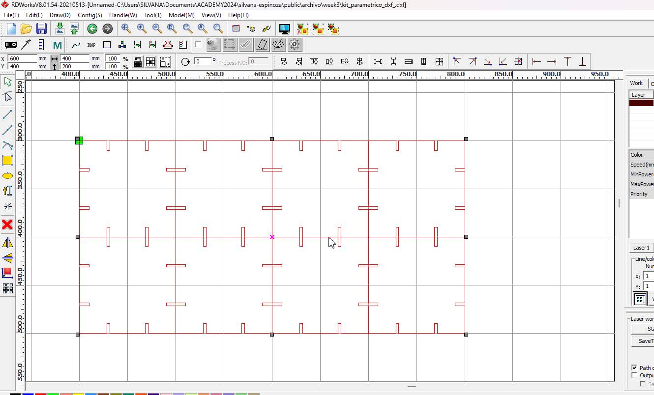
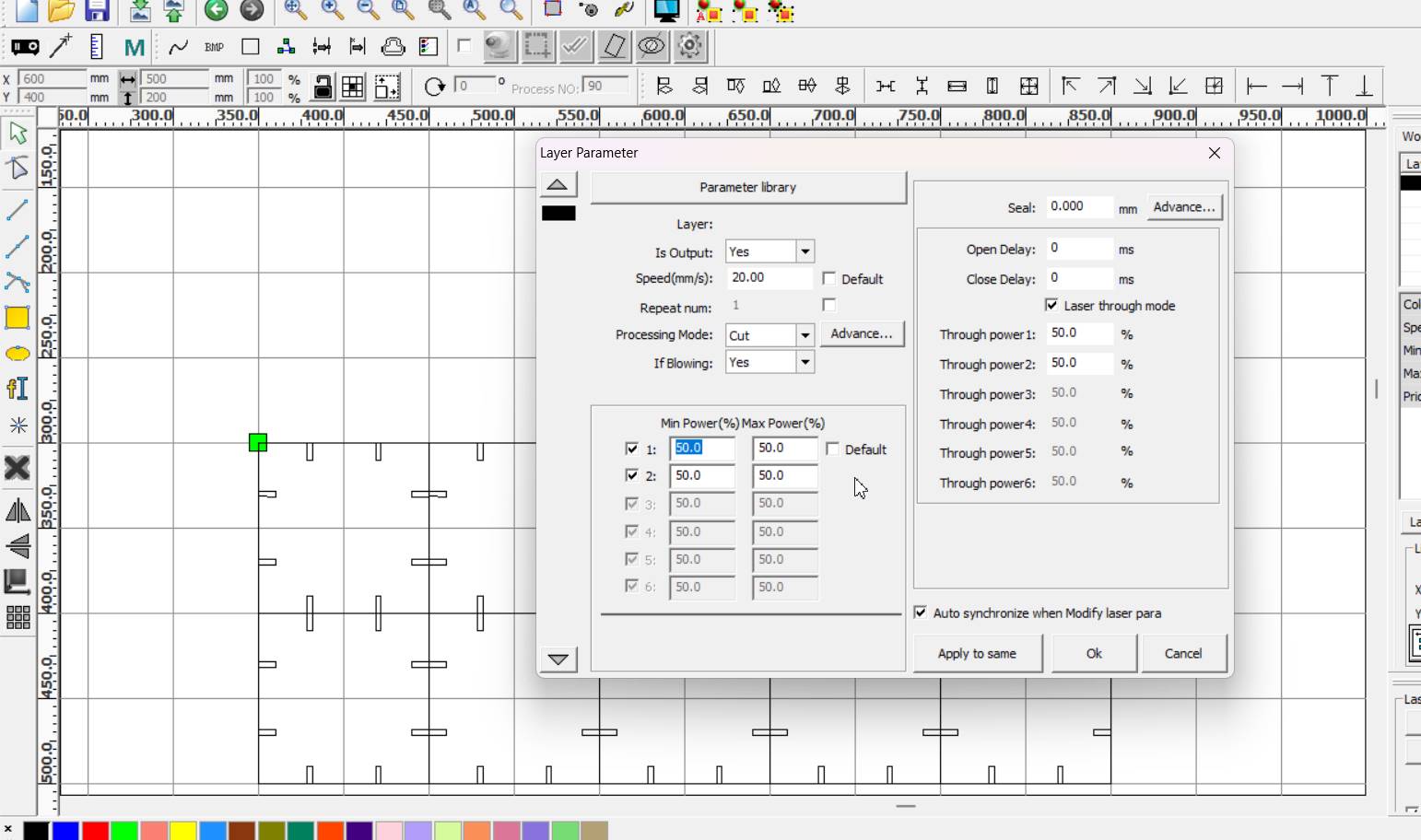
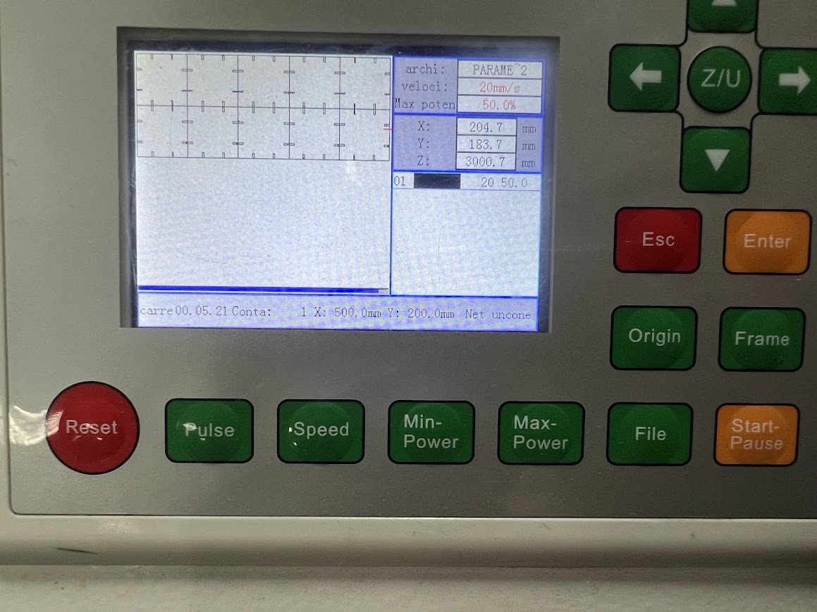
When you have all the configuration ready for cutting in this case, speed 20mm/s and a power of 50, we save the file in .rd on the USB, and we place it in the laser cutter, we read it in File, we copy the file On the machine, we press enter and select Frame to know the path of the laser, remember that you must first check that it is calibrated, this will depend on the thickness of the material you use.
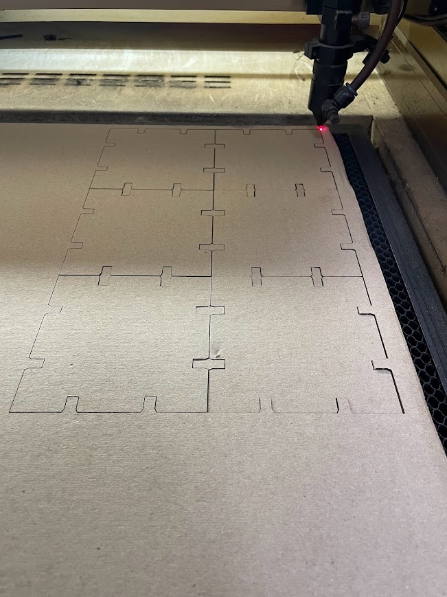
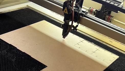
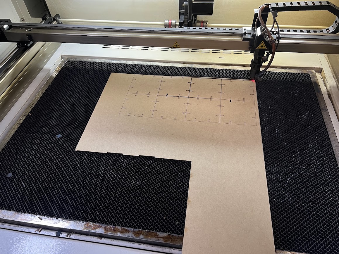
On this occasion I used scraps of 3mm MDF, search all the laboratories to reach the quantity of 26 pieces.
The last pieces already cut, with the excitement of seeing how it turns out.
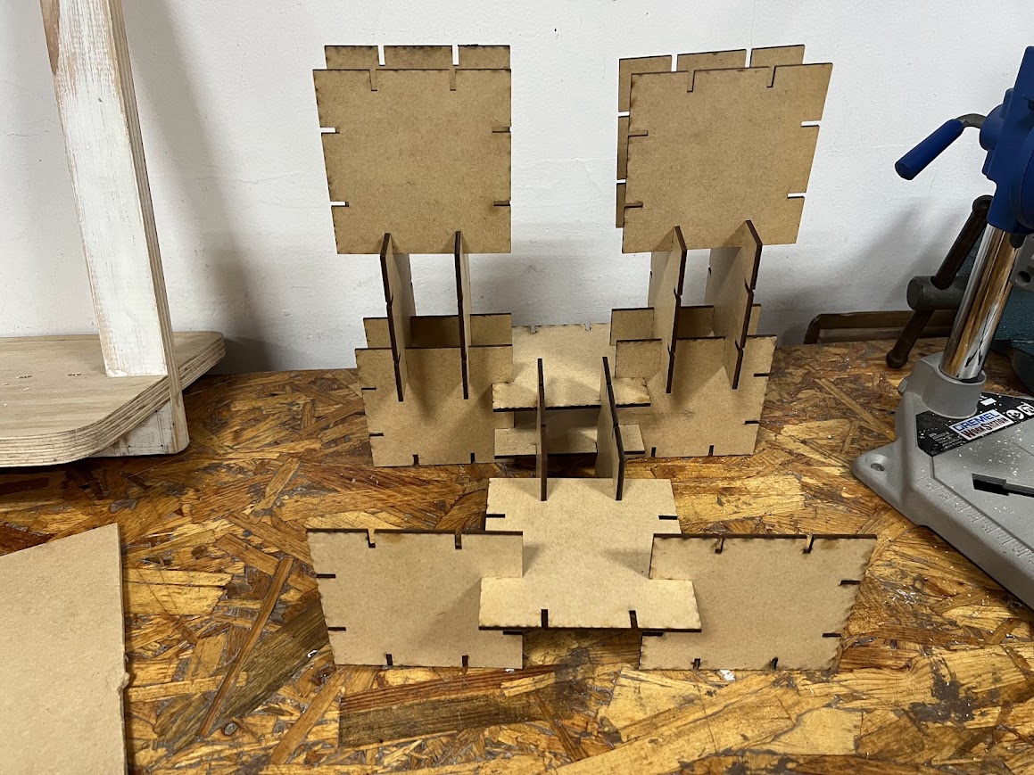
Here I really liked that it fit tight, in my previous versions I made the fits with 3.1mm, now they are at 2.95 mm and it fits snugly and nothing comes apart.
Take kerf into account when designing for assemblies
With the pieces I made, which have a size of 10 cm I made.
I loved! so I'll leave it on my desk in the Garage Lab.
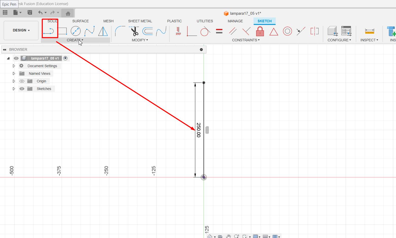
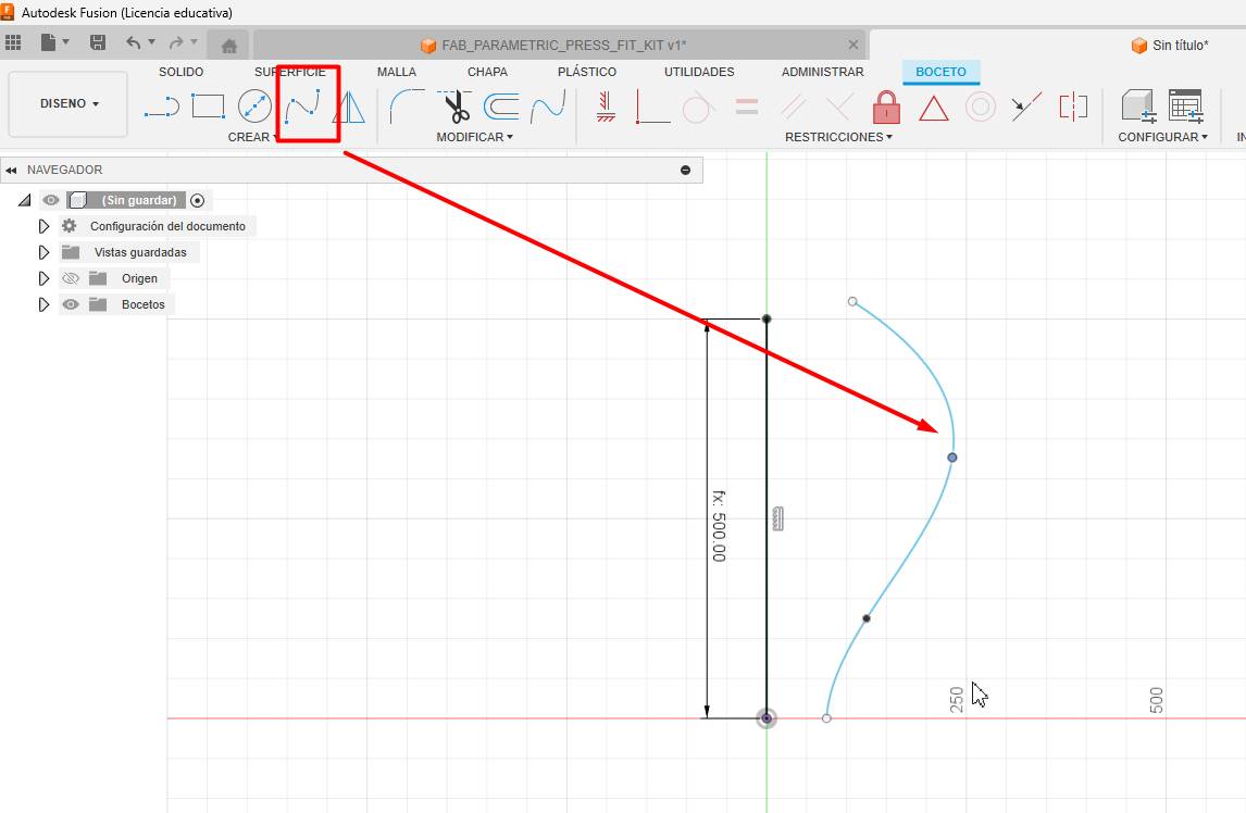
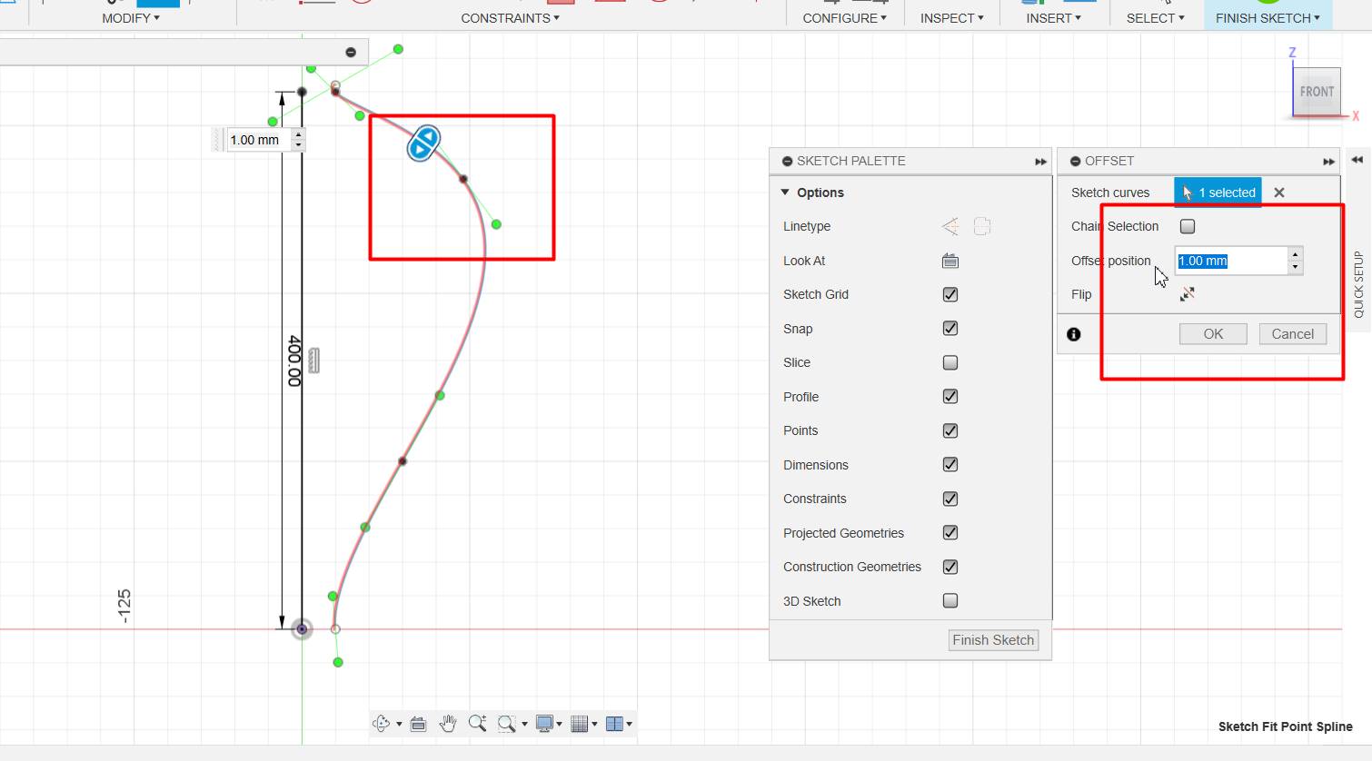
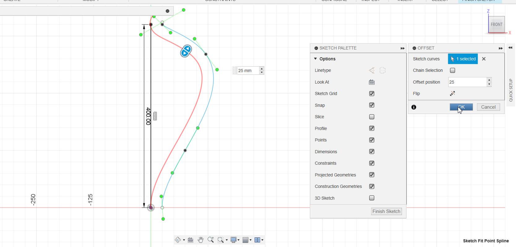
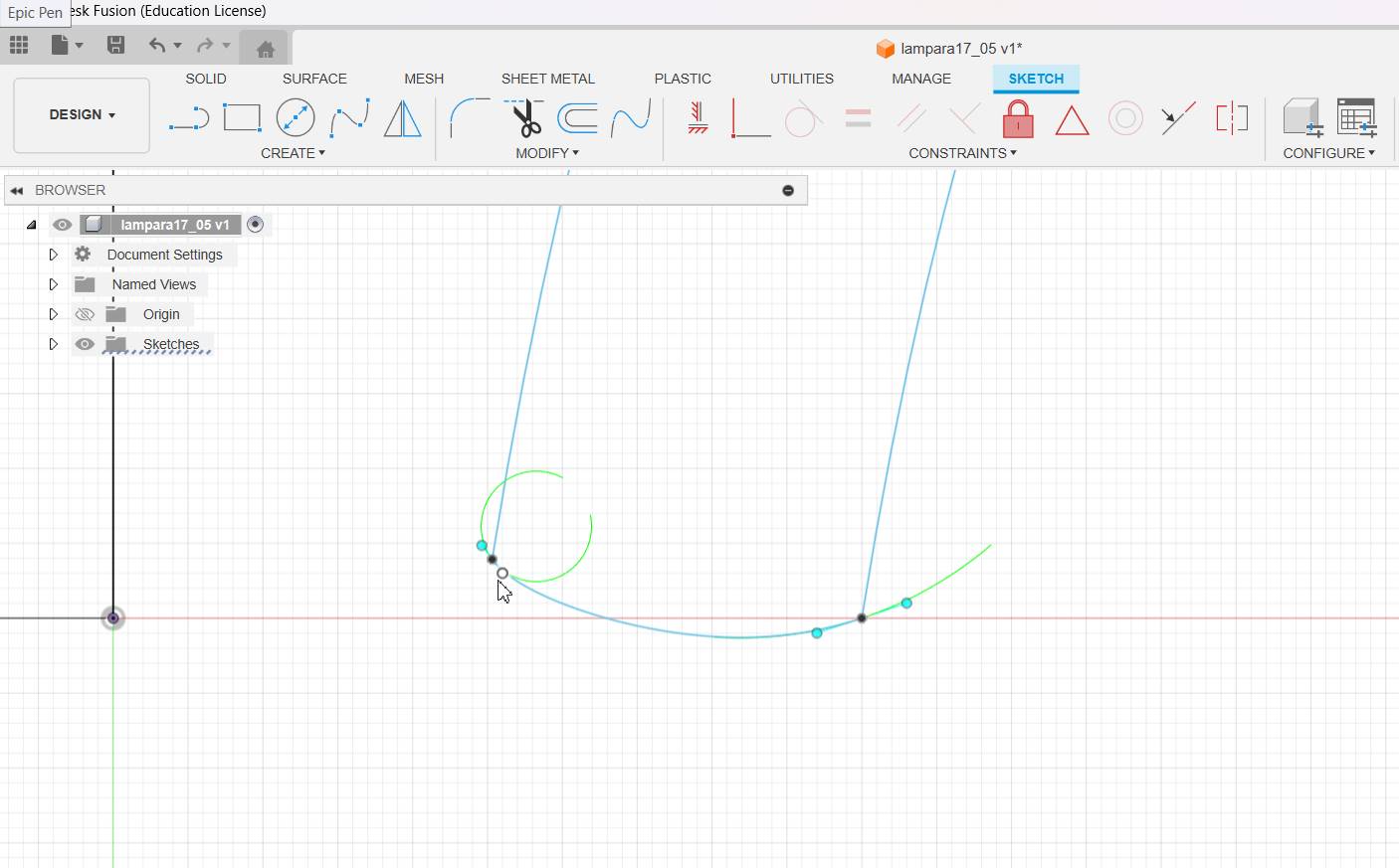
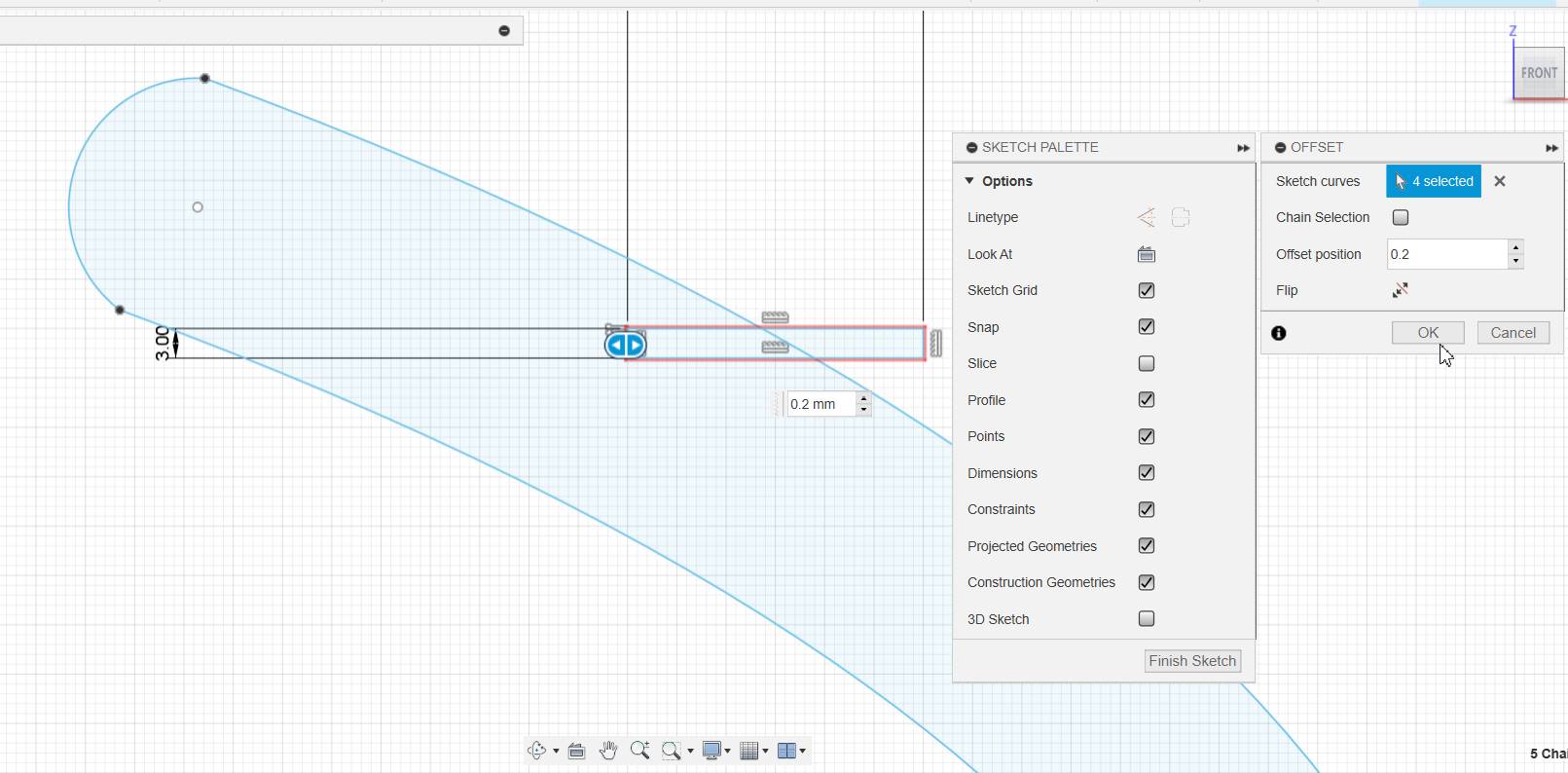
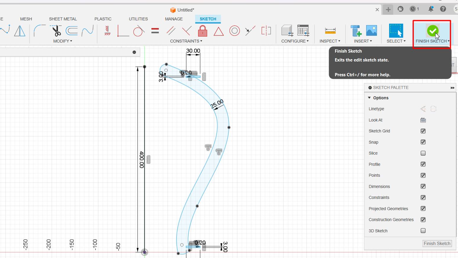
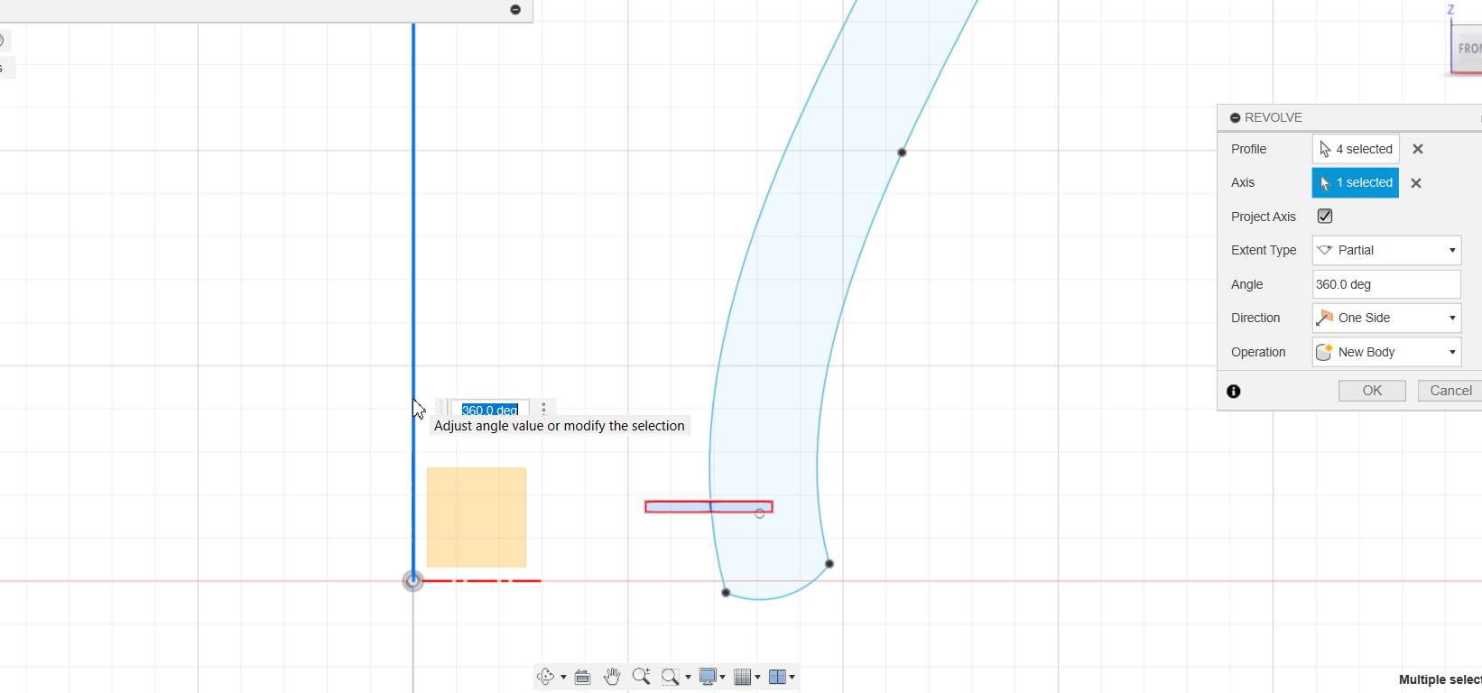
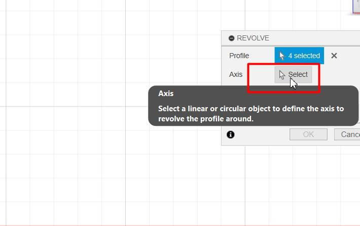
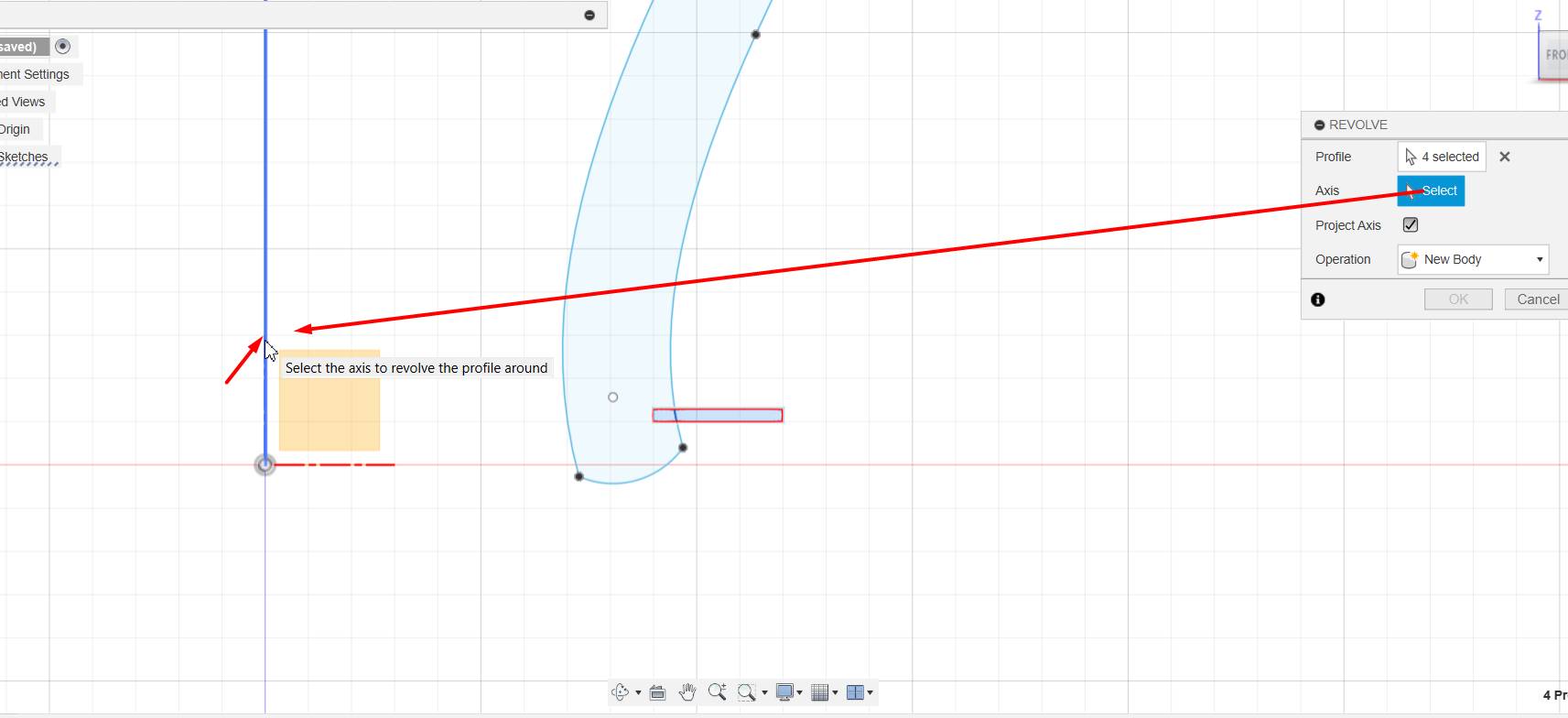
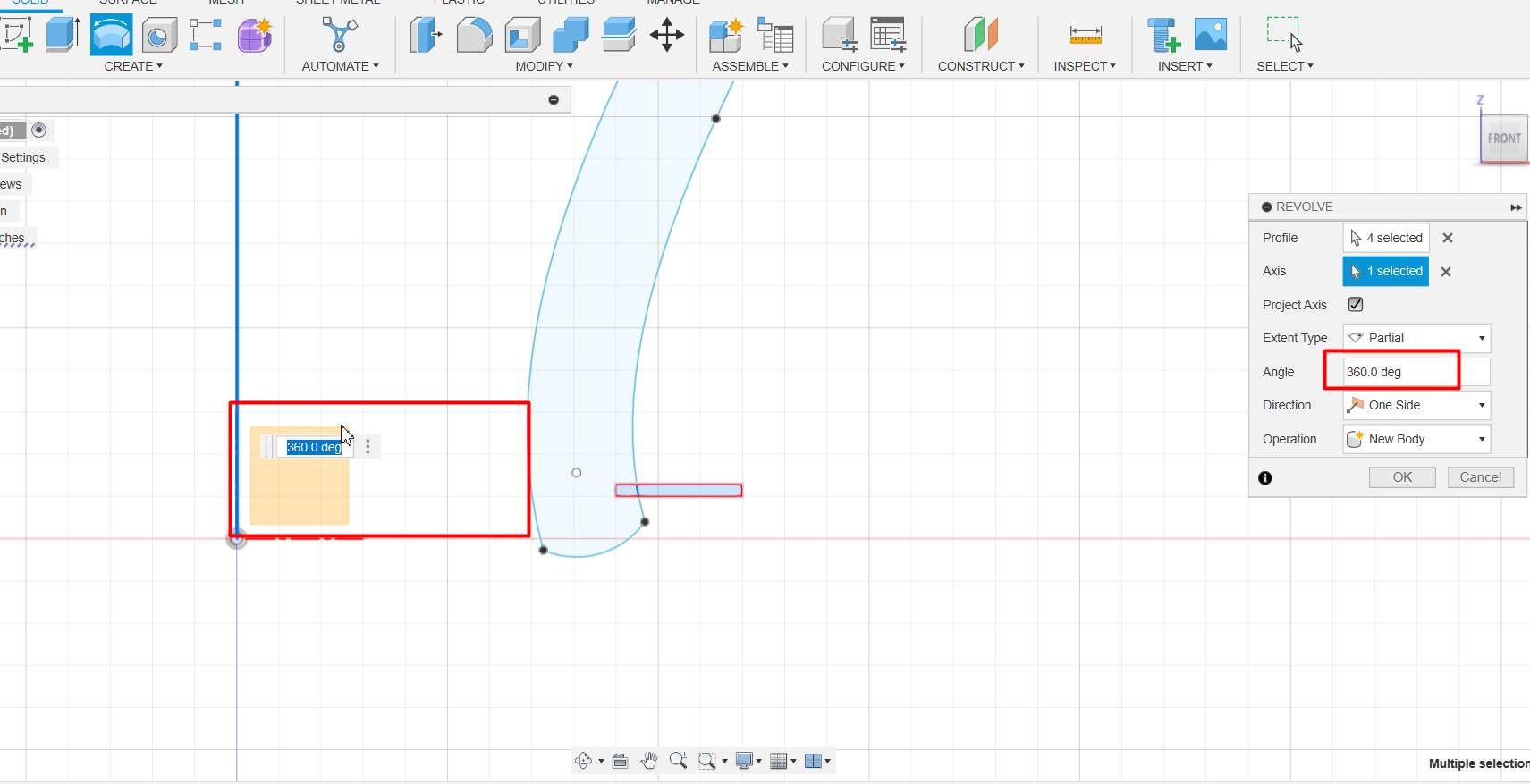
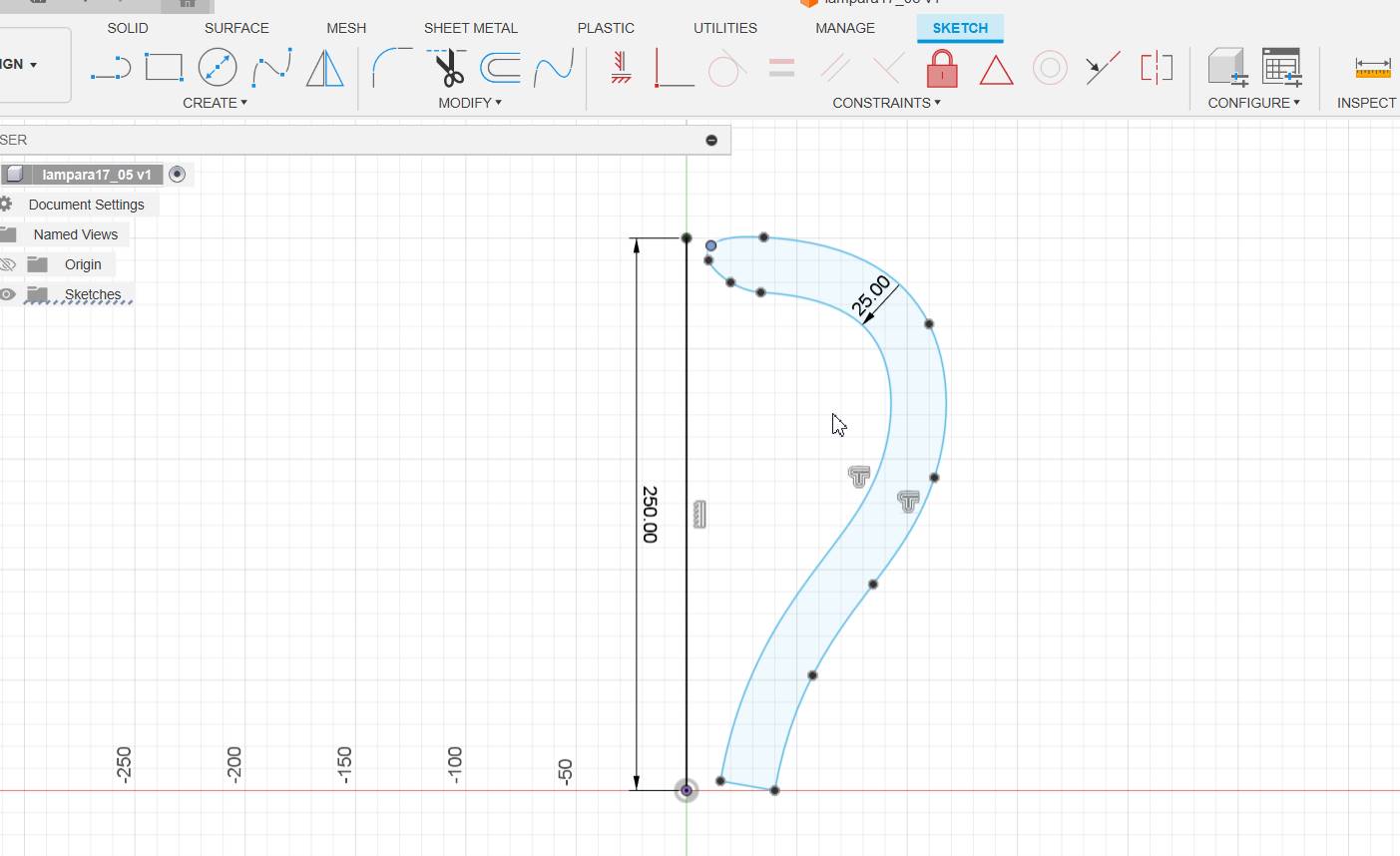
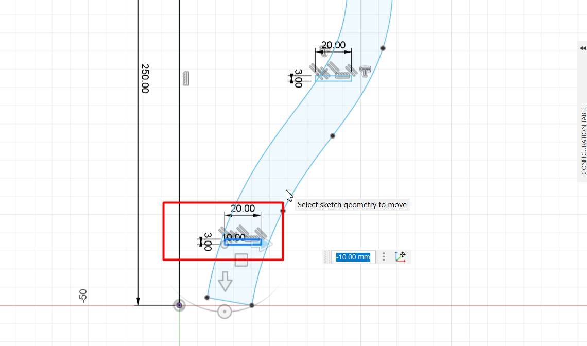
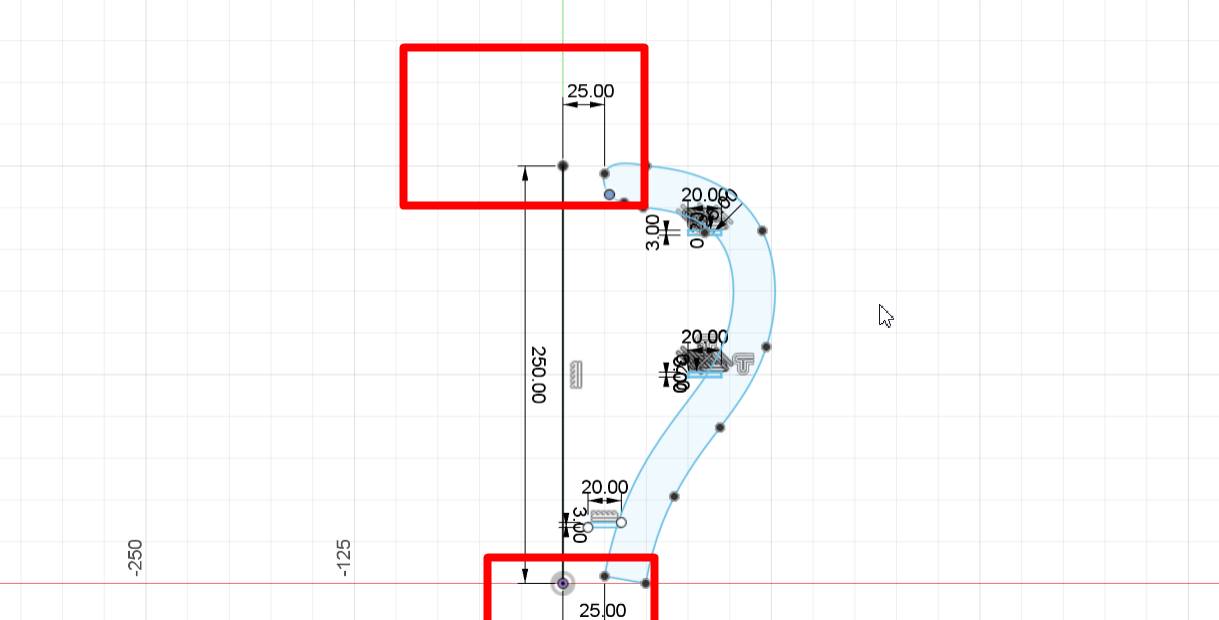
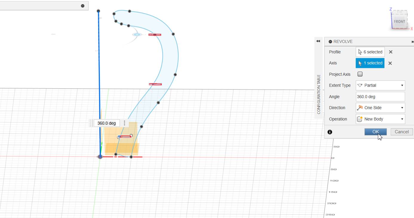
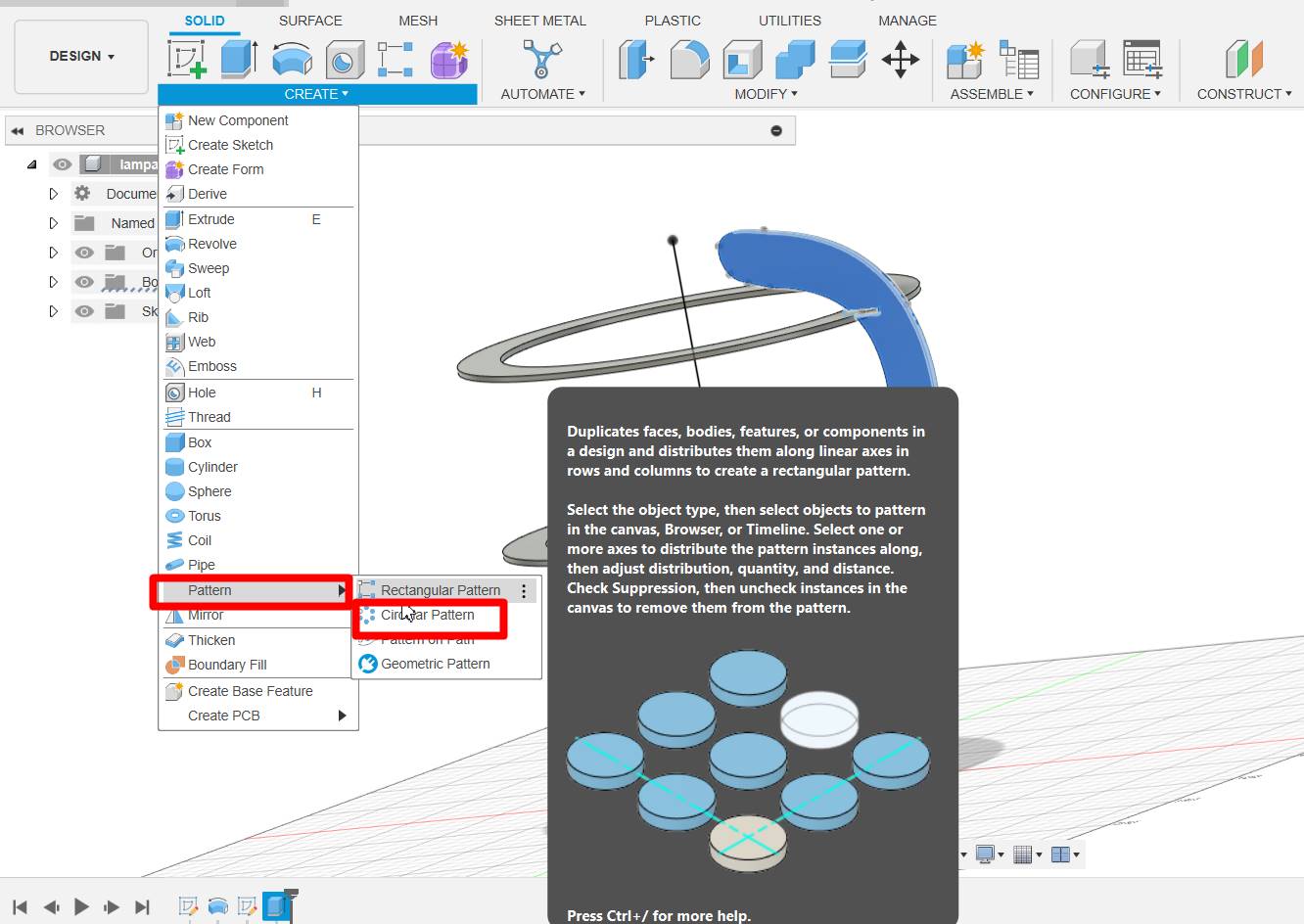
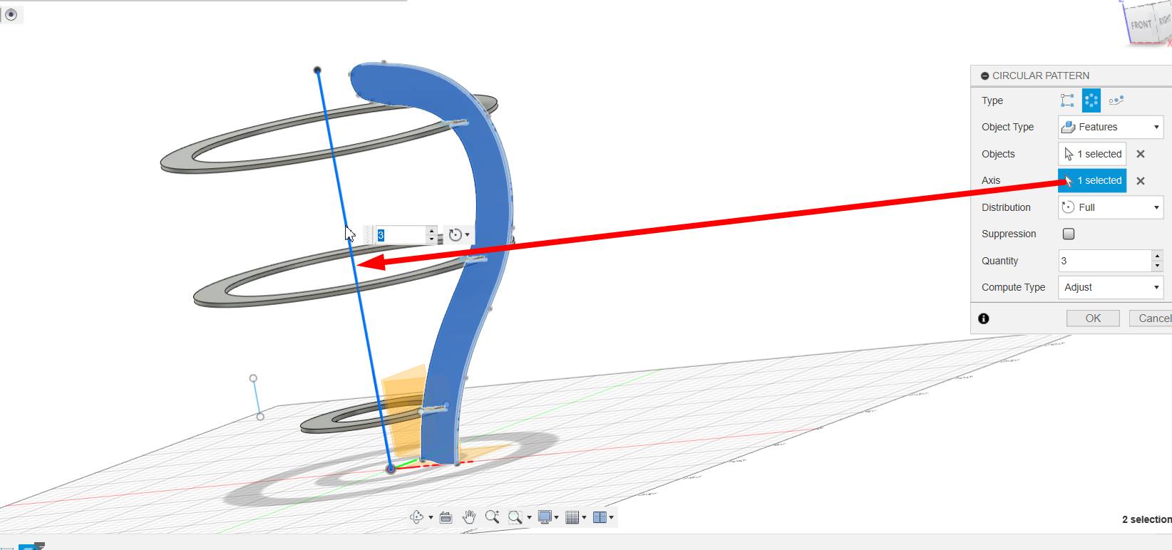
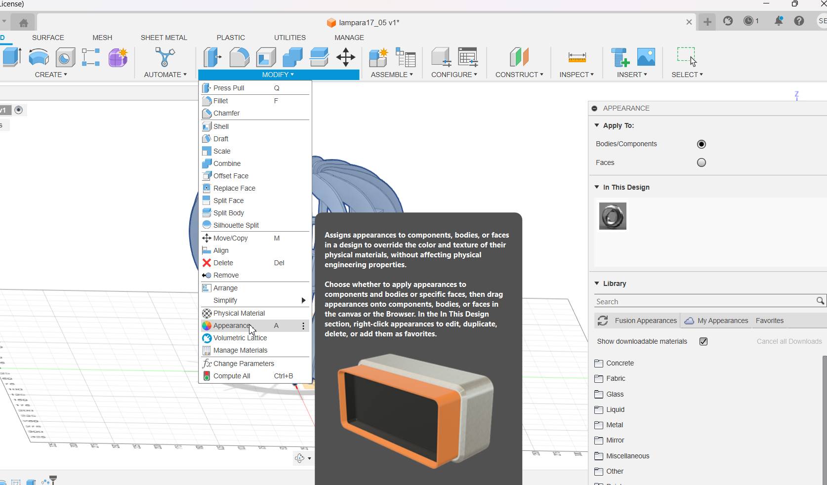
Fusion 360
I was using that program more to explore, I liked it and now it is not difficult for me to learn more functions.
The first thing I saw was being able to make it paremetric, adding the parameters and measurements.
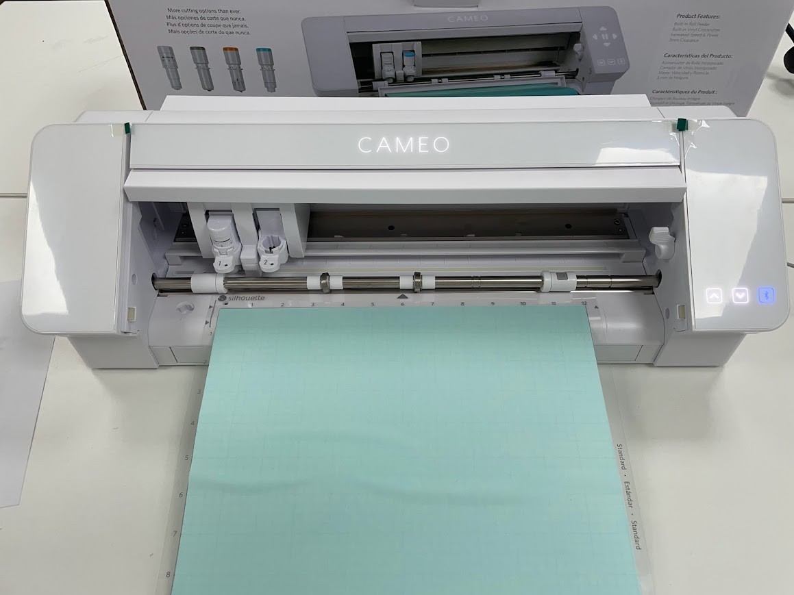
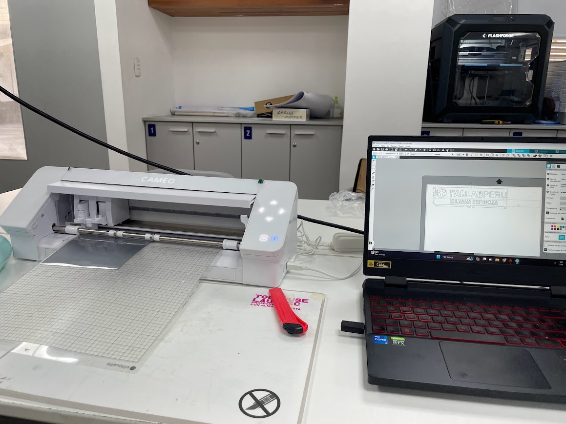
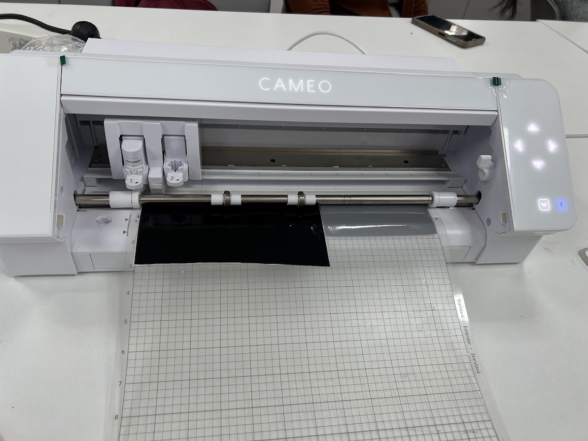
Silhouette CAMEO® 4 is the most complete cutting machine for personal or commercial use on the market.
With its powerful blades you can cut more than 100 materials such as paper, cardboard, decorative and heat transfer vinyl for textiles,
mica, EVA foam and different fabrics, with a maximum width of 30 cm. and a length of up to 60 cm. with the optional cutting base and up
to 18 meters long for vinyl. Thanks to its optical reader you can cut pre-printed files. In addition, you can make color drawings or sketches
by replacing the blade with Silhouette pencils. This new model incorporates sensors for different blades, is three times faster and has the highest cutting force on the market.
DESCRIPTION
Cameo 4 cutting plotter
Cutting force: 5kg
Machine dimensions: 56.99 cm x 19.50 cm x 16.99 cm ( 22.44 in. x 7.68 in. x 6.69 in.)
Machine weight: 4.5 kg
Touch buttons embedded in the plotter housing
Cutting width: 30 cm
Double carriage to work with two tools simultaneously
PixScan compatible
Built-in roll feeder
vinyl cutter
Maximum cutting depth: 3mm
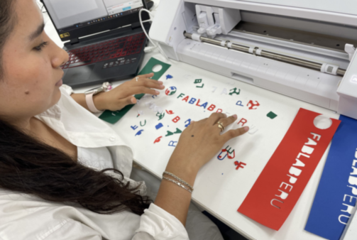
You can cut all the papers you want, the idea is that you make fun designs and the machine can replicate them several times more quickly.
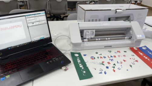
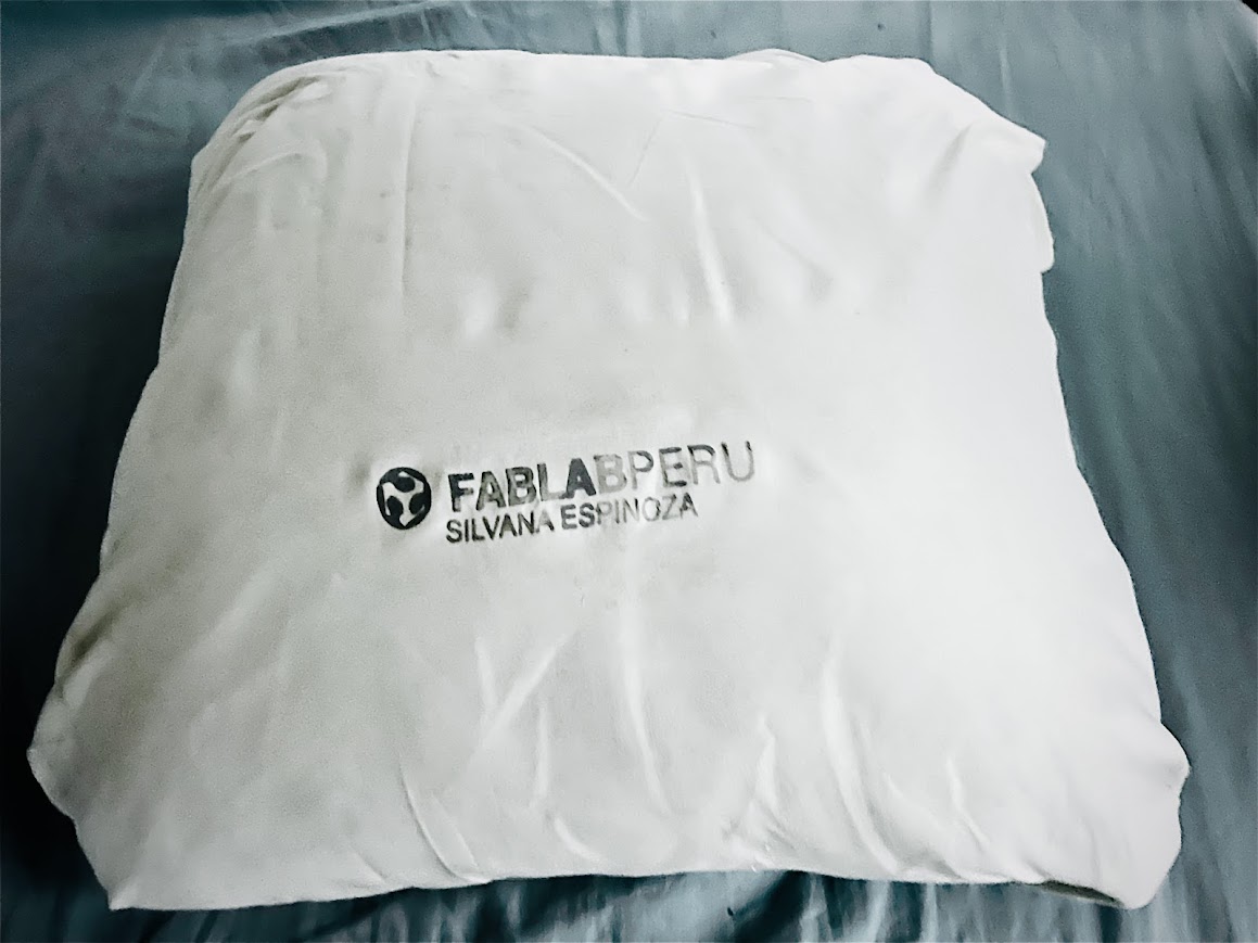
Since I didn't have vinyl in my laboratory, I made the letters for my agenda with thick cardboard.
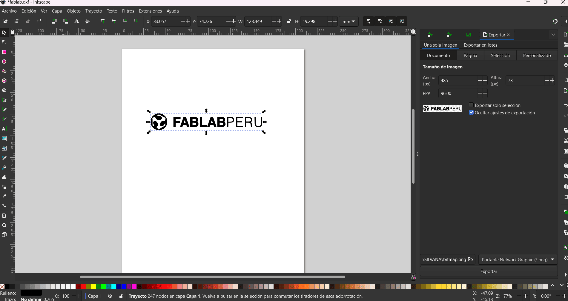
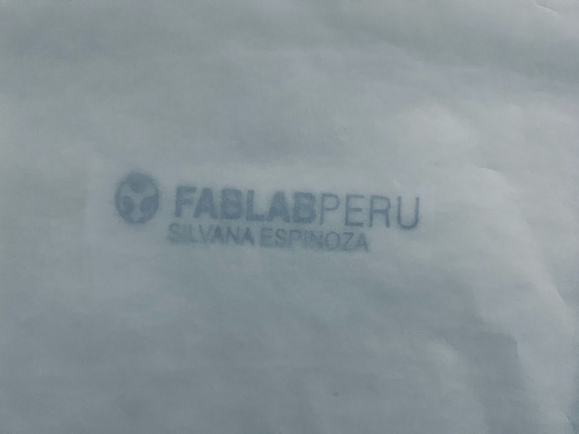
well I started with the logo of the Fab Lab Peru that I had on pgn and I transferred it to inkscape which is one of the tools that I learned to use, this tool helps me to be able to vectorize and save it in svg to cut
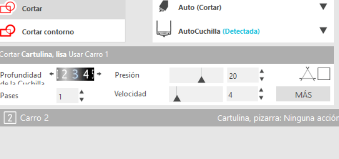
I have been making changes to the depth of cut.
here my letters that were not correct
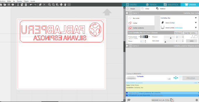
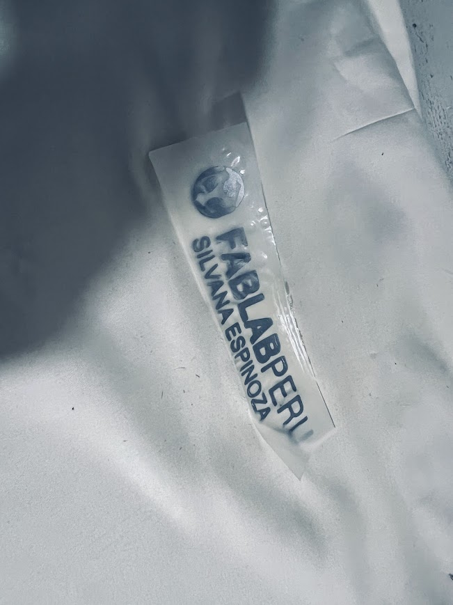
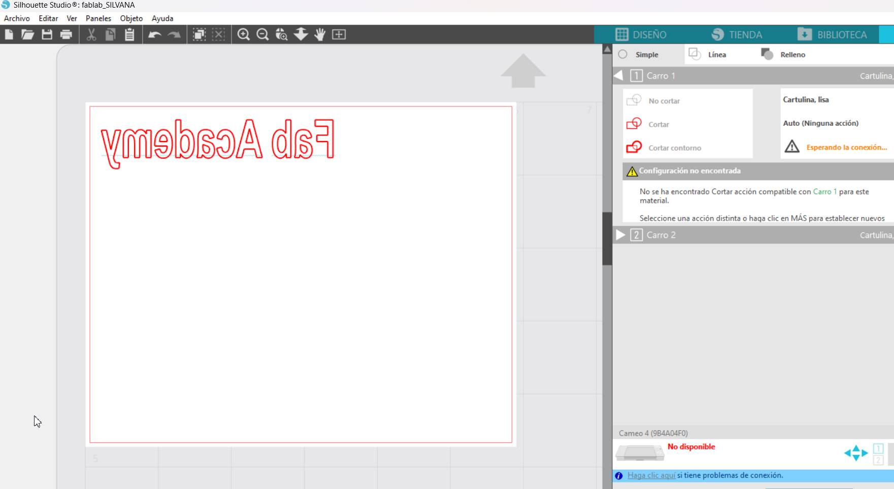
Here I already made a mirror and with this it should be ready to iron on my polo shirt
AutoBlade 2 cutting blade (new, adapted to the new CAMEO 4 format)
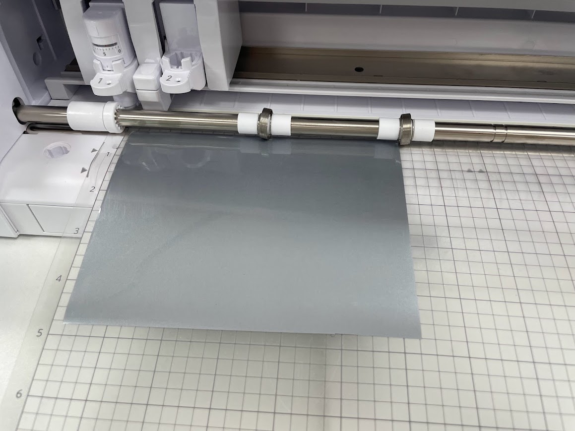
Here we paste the vinyl that we will use
Glue the fabric vinyl the less shiny side up
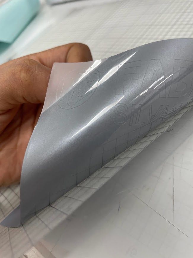
Clearly it went wrong for me T_T
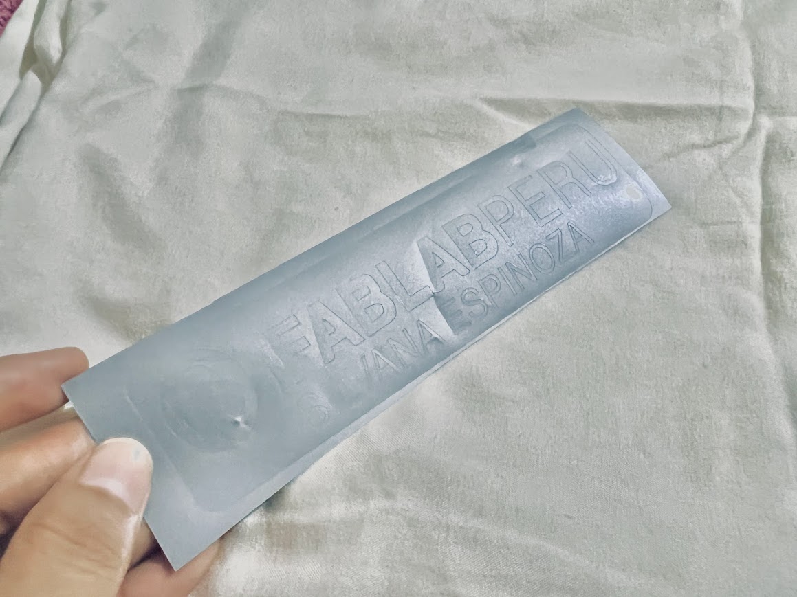
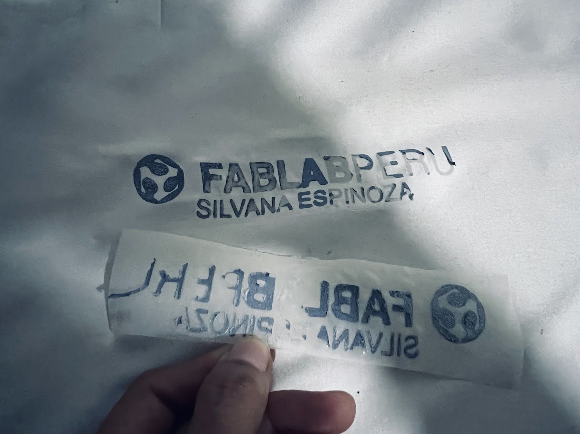
Here I did wrong with the fabric vinyl, you have to cut it in a mirror, I didn't have any more material so I'm left with the wrong cut but I leave with a lot of knowledge of these flaws.
I got more material, my friends from Garage lab and Fab lab UCSUR gave me some scraps to do my tests.
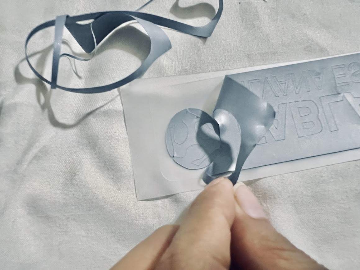
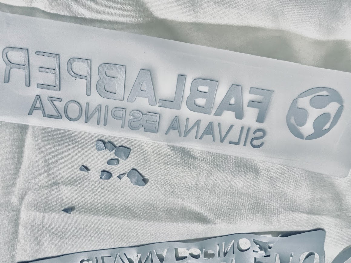
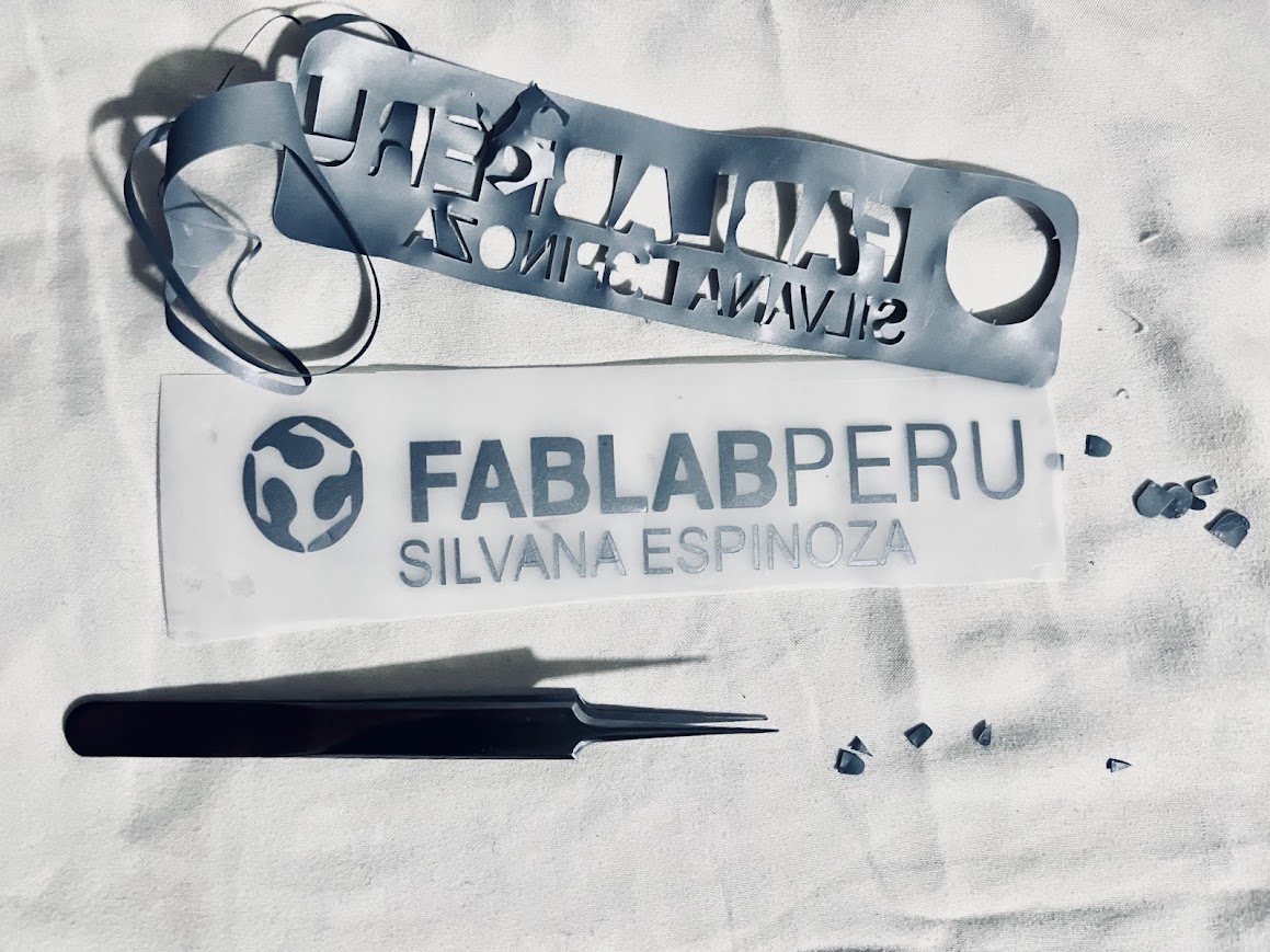
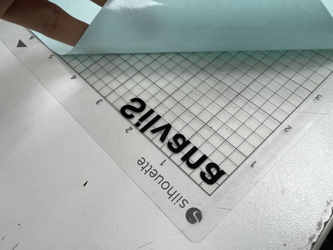
Now if I cut in a mirror, I inverted the image.
Take off the edges so that only the letters remain on my case.
I took everything out here but the small details were missing.
Here I took a pair of tweezers to be able to remove the most difficult ones.
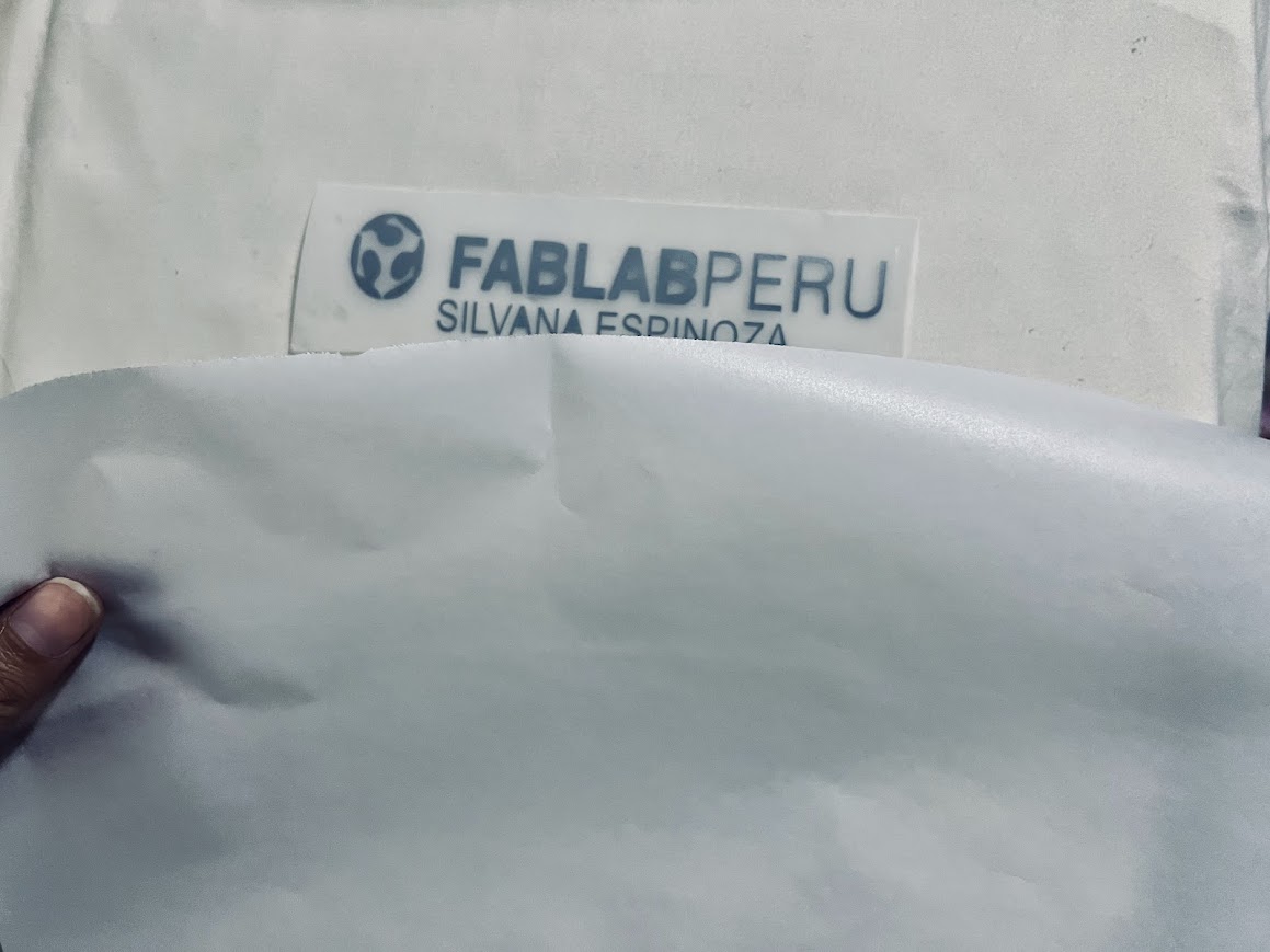
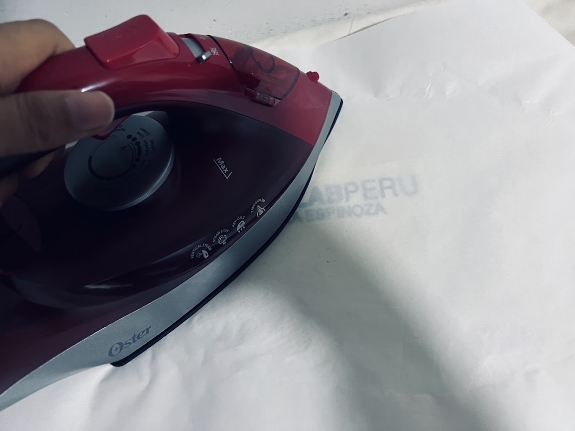
When everything was left, I put parchment paper, it is more resistant to the high temperatures of a domestic oven.
I put the paper on top so that it resists the heat.
I set the iron to temperature level 3.
Apparently my iron is too hot so it didn't work as expected.
It went wrong but you can see the letters.
I could do it again but my cushion is fine
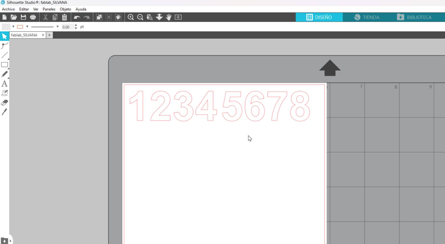
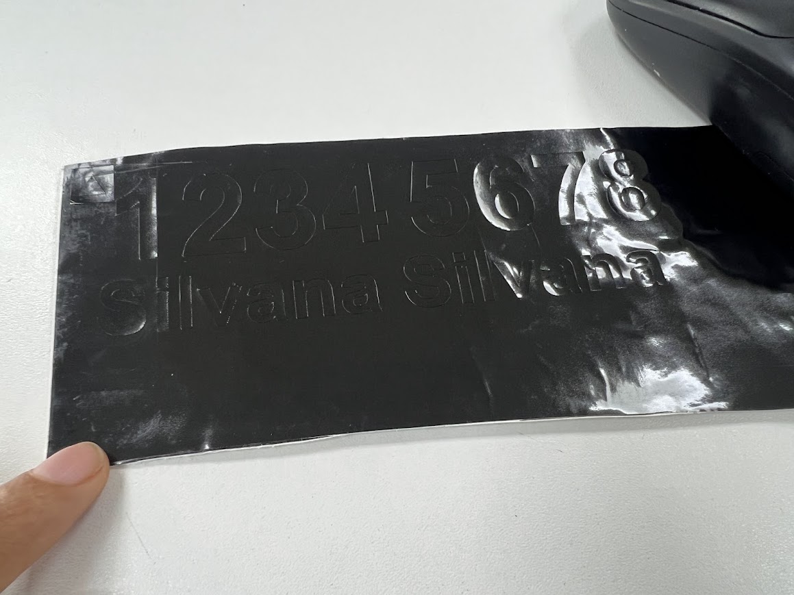
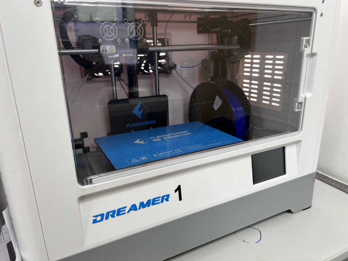
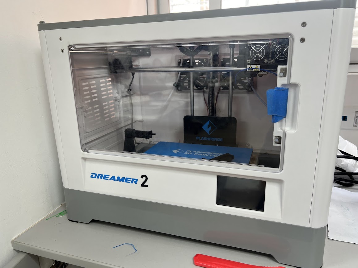
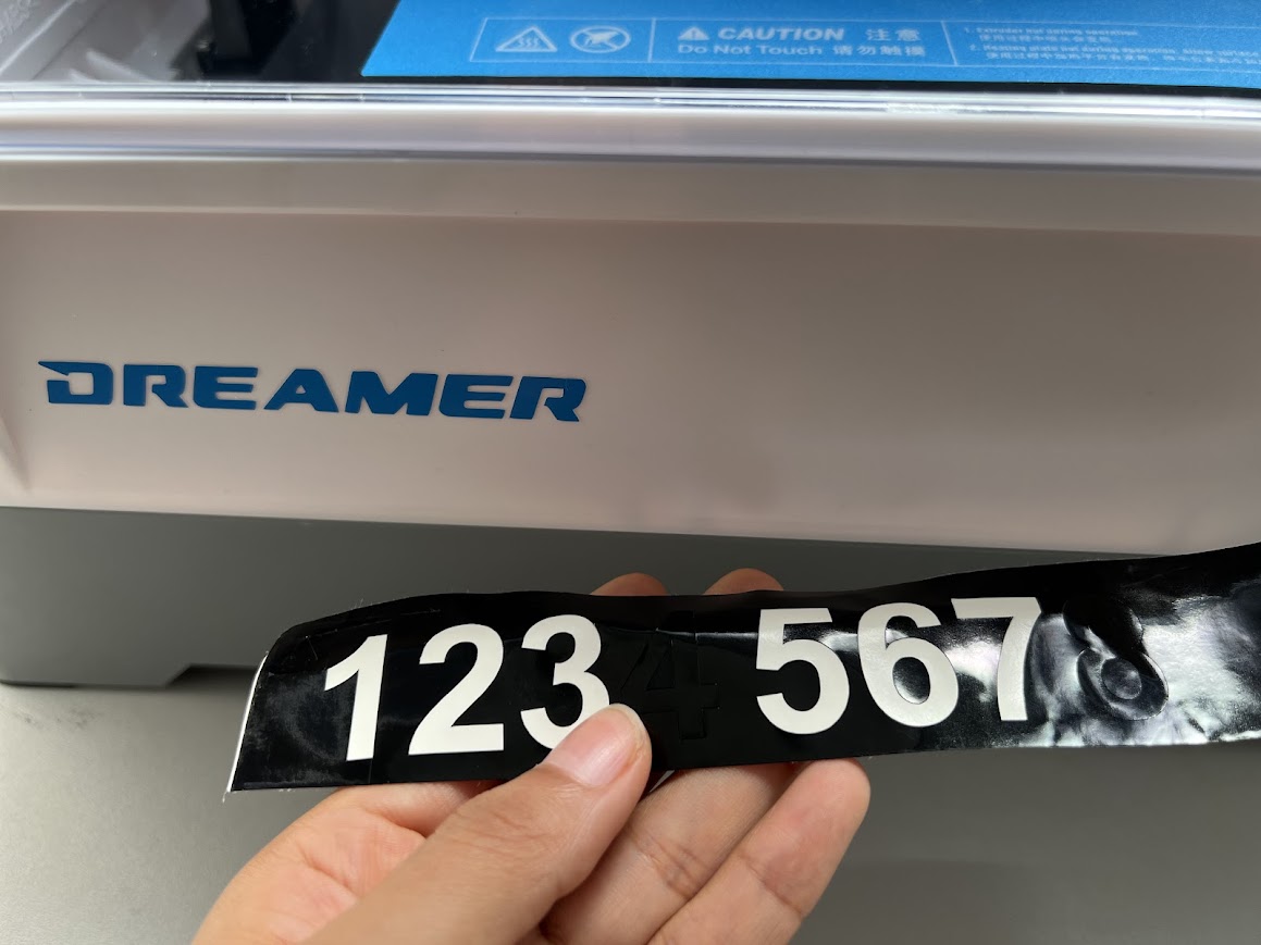
I will make an even number to label the printers that we have in the Creatispace laboratory.
There are 8 printers so I did
from 1 to 8.
I also went back to writing Fab Academy letters but as you can see I have to mirror it, I did it, no more mistakes.
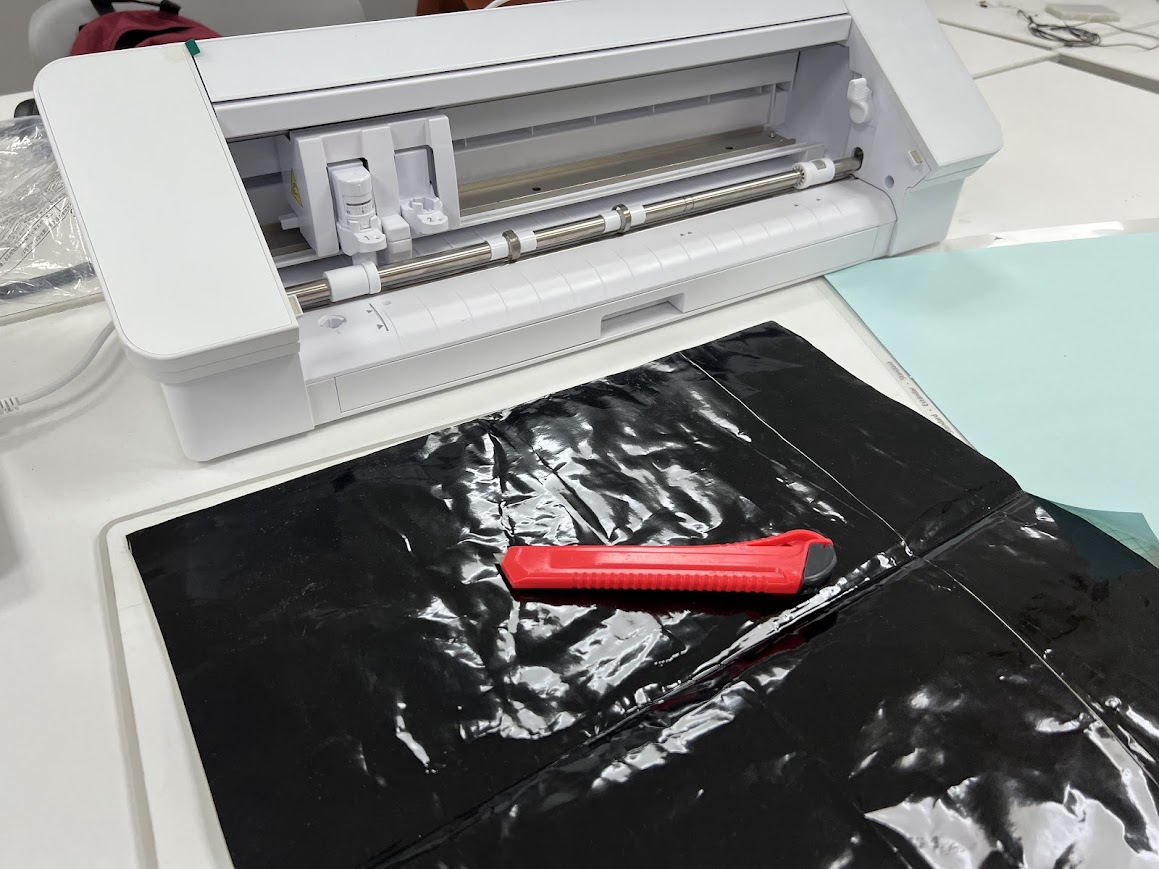
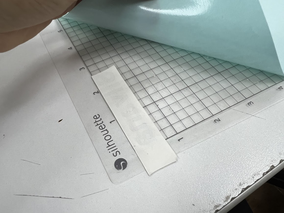
Now take a piece of the black vinyl, it is a little wrinkled but it still works.
place a piece at the beginning of the base
I had it cut and it came out perfect, it already had the correct depth because I had done this before.
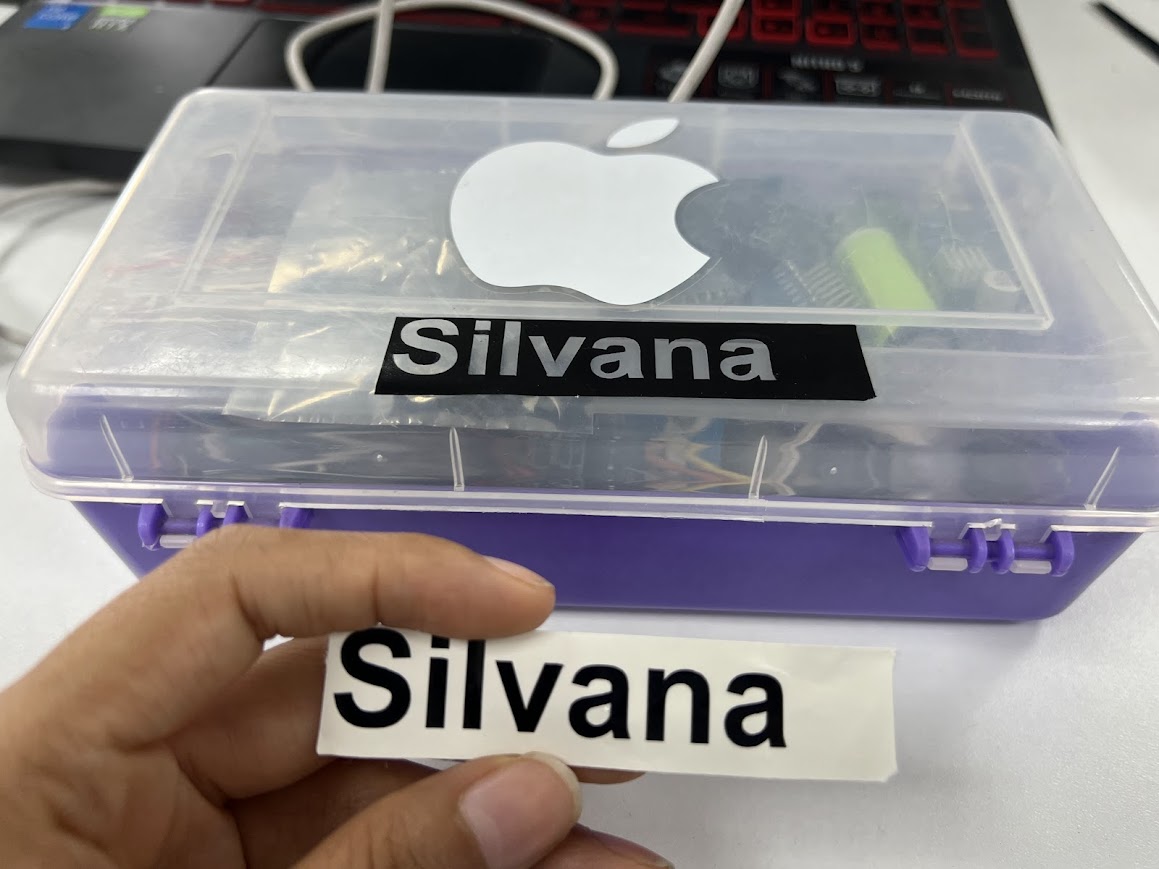
I had some boxes in the textile electronics laboratory and I wanted to label them so that the other teachers knew they were my things.
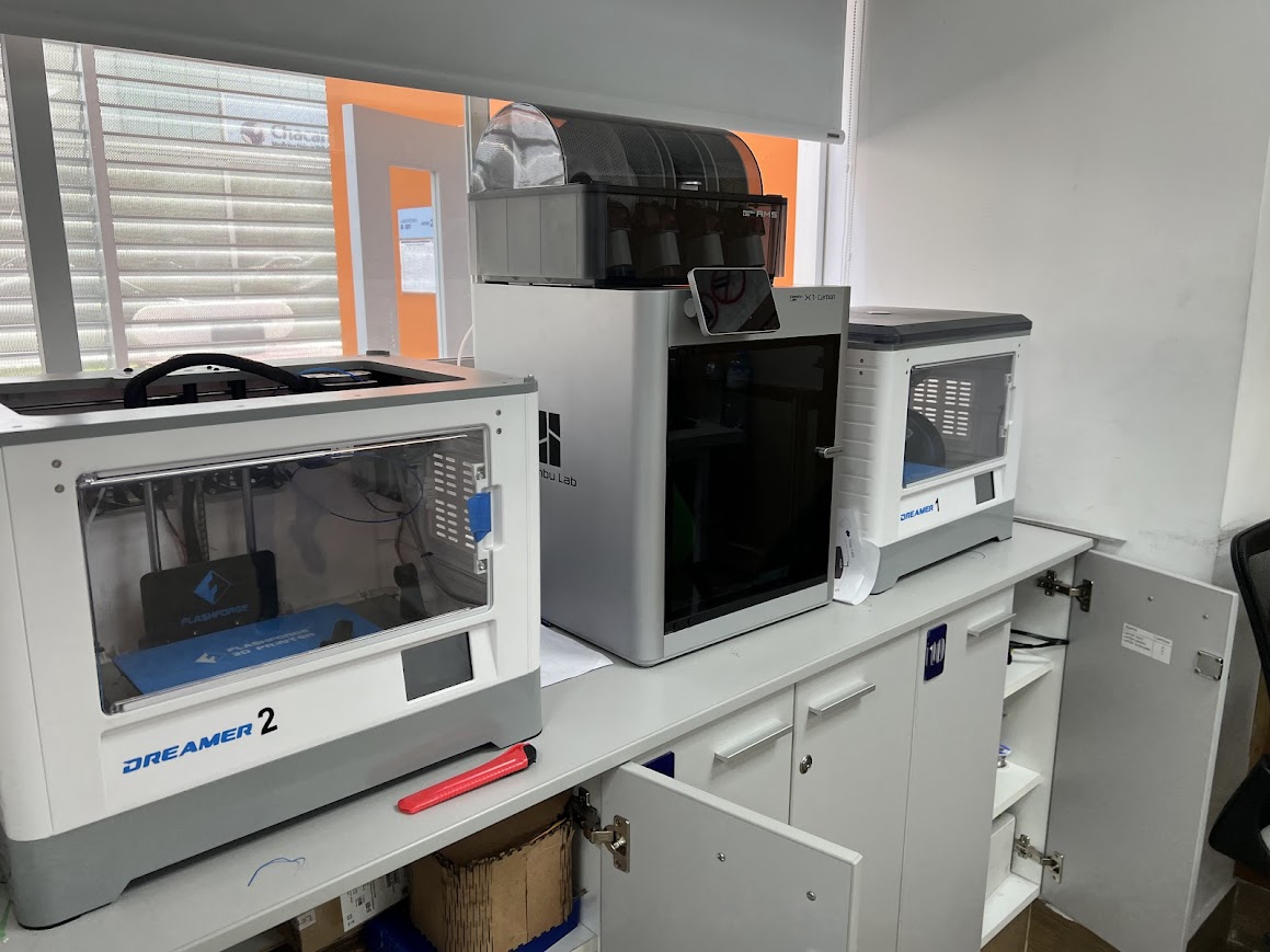
and here I put the numbers to the printers since you had problems being able to indicate which printer was having problems or lacked maintenance.
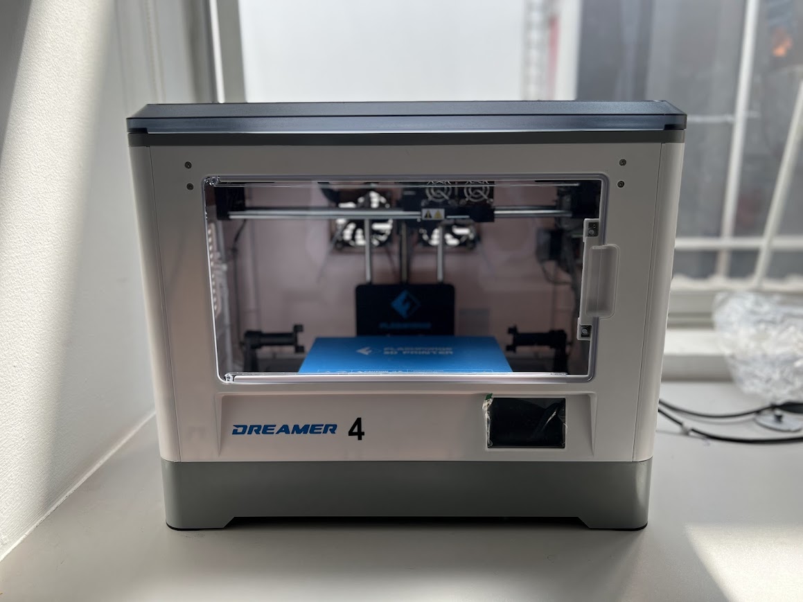
I put 2, we have 4 dreamers so it was necessary to number them.
They turned out very well, I like it.
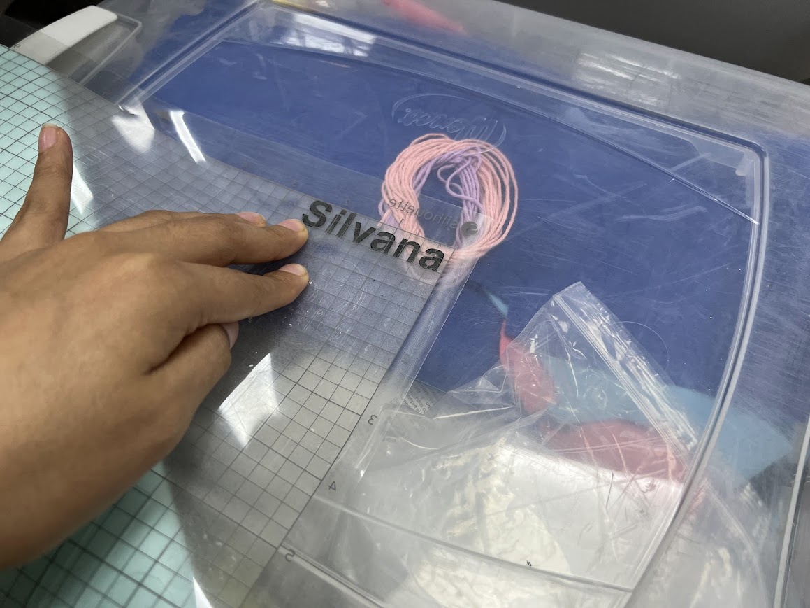
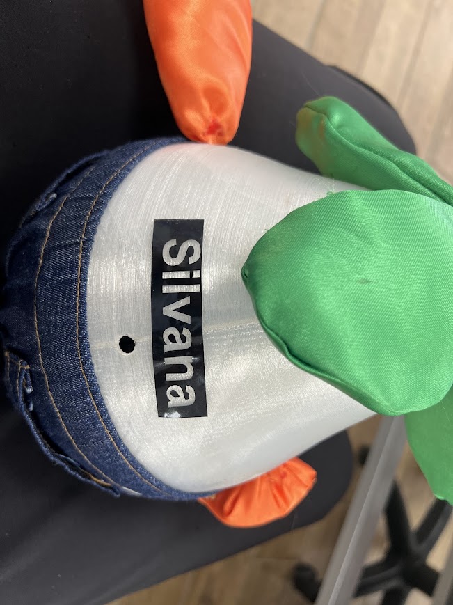
here I continue with my name on my boxes
You didn't have transfer paper but I managed to use the base of the cutter.
If it worked, do this technique.
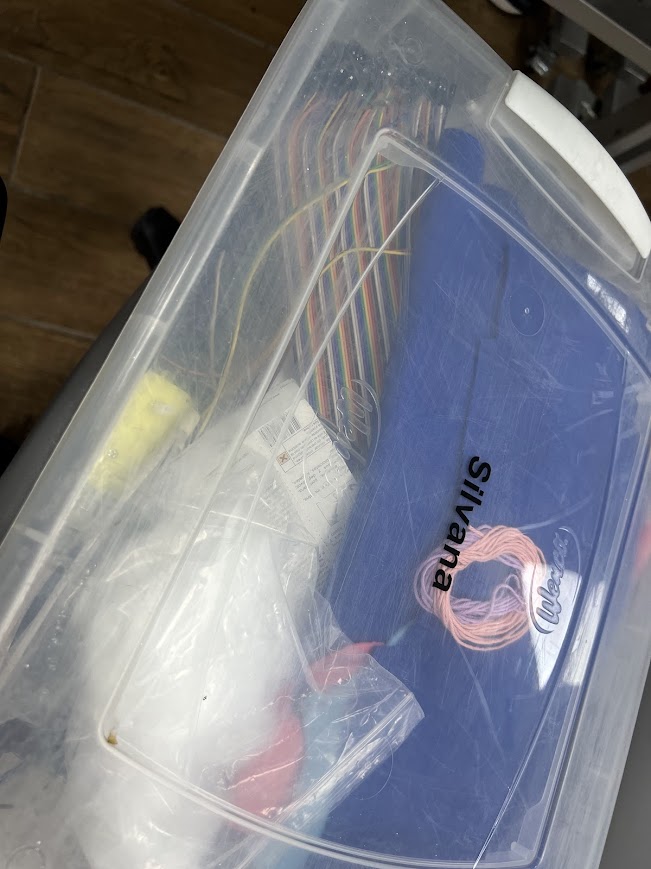
I was able to place it in my box and the letters stayed very well.
I love it! Successful result.
Now I put the surplus into some projects. hahaha I already wanted to label everything.
I went to the other room and placed the remaining numbers to differentiate the dreamers.
I went to the other room and placed the remaining numbers to differentiate the dreamers.
This was the last one, everything turned out very well.
My first tests with the 3mm MDF, I thought the soft fit would be an option so I put 3.1 so it wouldn't be tight, but that was a mistake, so I did it again with 2.9mm.
Something important before starting something new is to delve deeper into topics, that happened to me in textile vinyl, so I recommend that you better be able to review some textile vinyl tutorials that I will leave you and they helped me a lot.
What went well
In rinho I managed after two days full of tutorials to make my algorithm for my part in parametric design, it was quite an achievement.
What I would do difherently
First I would focus on learning how to handle only one design program well, I got excited and tried to explore like three and that took up too much of my time, when the assignment only asked for a parametric design kit, I tried to see more options and I got behind.
I recommend that you focus on a program that you like the most and that you can do all the tasks it asks of you, and then in the process you can continue exploring when you finish the week's task.

