Computer-controlled Cutting
Week 3
Group assignment:
- Do your lab's safety training
- Characterize your lasercutter's focus, power, speed, rate, kerf, joint clearance and types
Group 1
Group 2
Group 3
Group 4
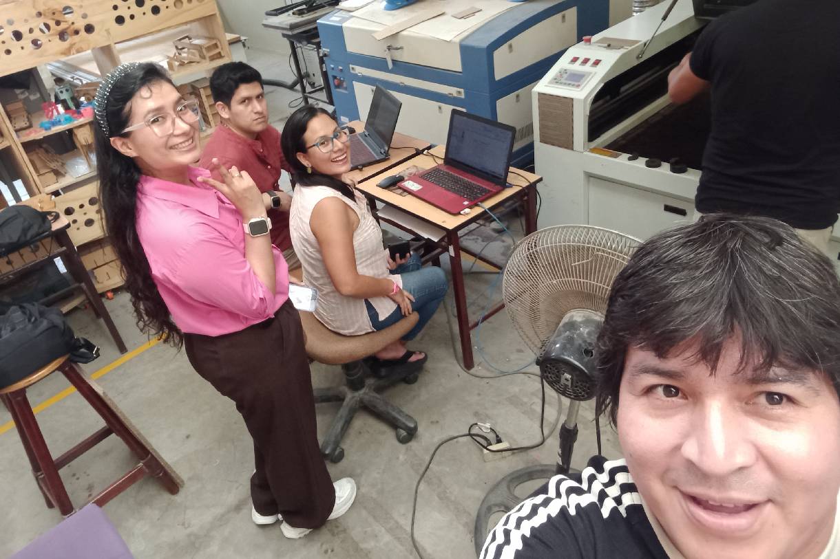
Group 1:
- Hans Moncca
- Maryori Vasquez
LASER CUTTER MACHINE
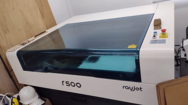
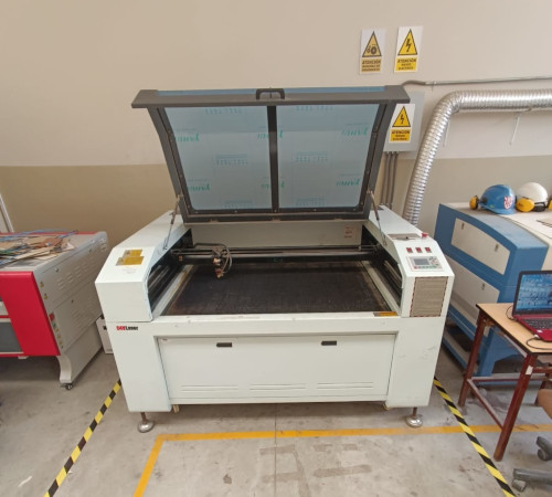
The laser cutter that we have at the Universidad Cientifica del Sur is the RAYJET R500. Which has the following technical specifications:
| WORK SURFACE | 1300 x 900 mm |
|---|---|
| LASER POWER | SEALED LASER CO2 DC 60 / 100 / 120 W |
| LASER SYSTEM POWER CONSUMPTION | 100 - 250V, 1100 - 1500 W |
| MAX PROCESSING SPEED | 1 m/s |
The laser cutter is used to cut materials such as cardboard, wood, acrylic and foam. Materials that are used by students who are studying architecture at the university. I learned to use the machine last year from my friend Maryori who taught me how to use it, but we always had doubts about the cutting configuration of the machine with the different materials, so we will take advantage of this assignment to have our value test for the different materials we use.
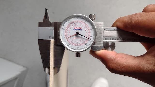
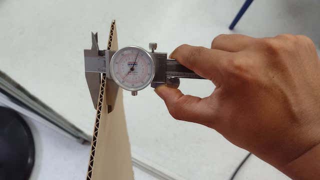
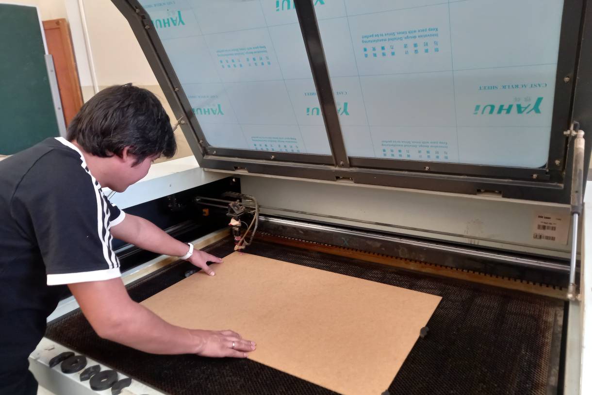
The materials that I will use to develop the task that is related to the laser cutter will be 3mm PLYWOOD, which is a sheet of wood and CARDBOARD of 4 mm.
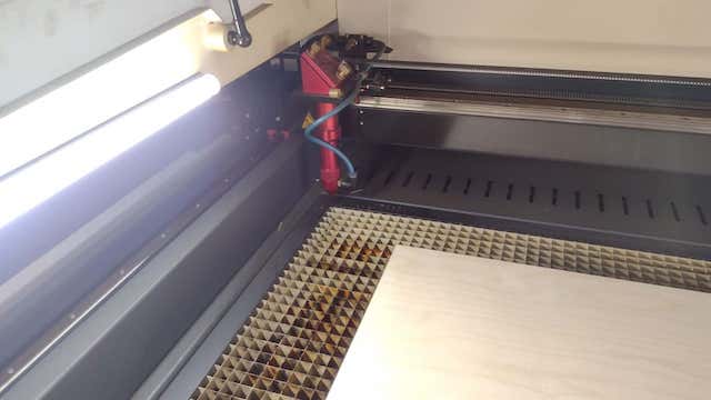
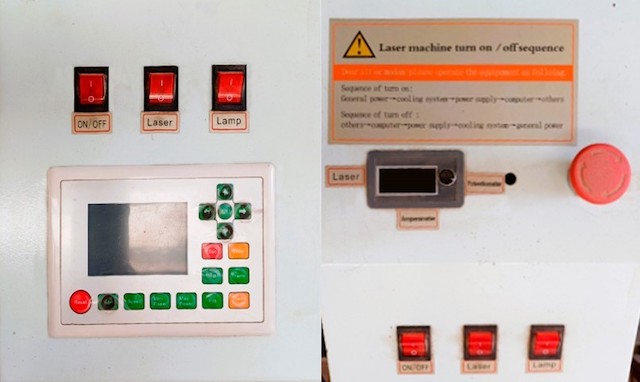
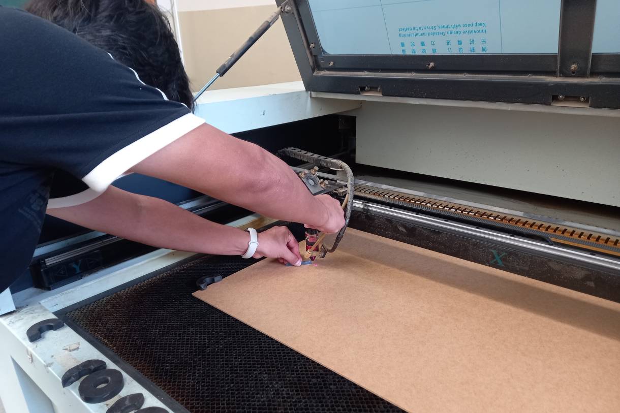
STEP 1: POWER ON AND HORIZONTAL AND VERTICAL CALIBRATION
To start using the machine it is necessary to calibrate the location of the laser because the laser point is located where the previous work was done.
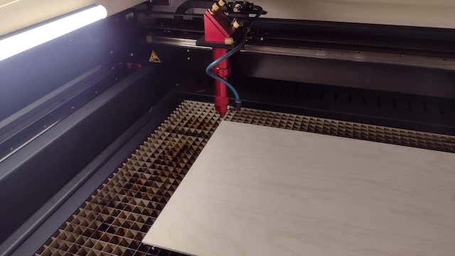
Therefore, for the machine to be calibrated in location again, we have to close the safety cover and it returns to the point x=0 and Y=0 that it has programmed.
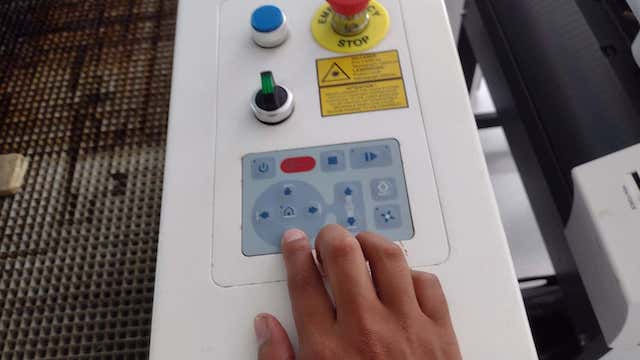
From that moment on, the user can move it manually with the buttons to the point where they consider it convenient to start working with the materials.
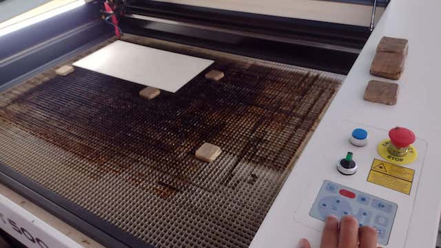
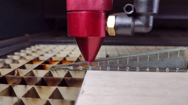
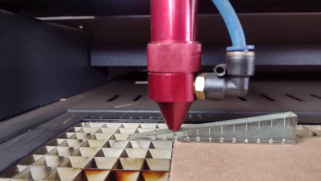
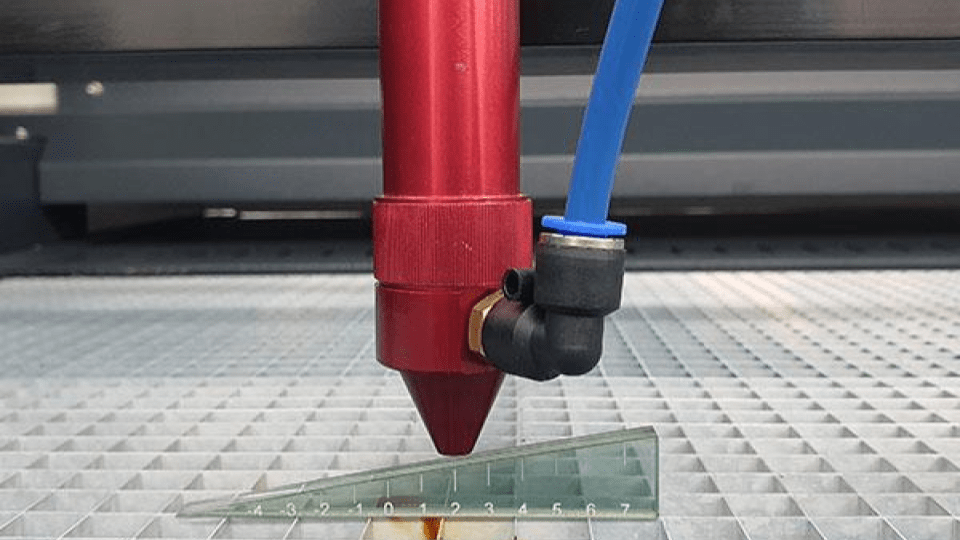
Finally, we have to calibrate the height of the laser, so using a triangular tool we can analyze the distance that the laser cut will have with the material. In this case we will use 2 distance units for correct work on both materials as recommended by the supplier.
STEP 2: CUTTING AND ENGRAVING TEST
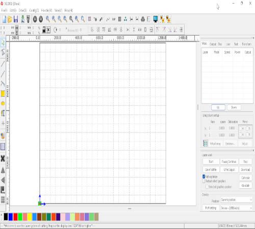
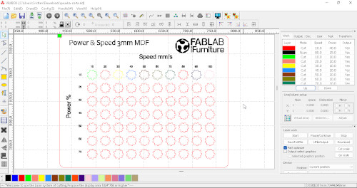
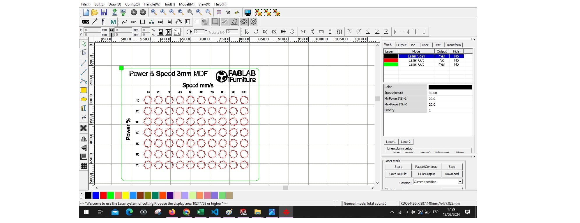
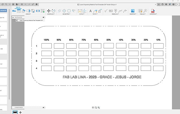
To draw the table of values that is made up of the power and speed of the laser, I started working on it in AUTOCAD a software that I use and it became easier for me to design the table.
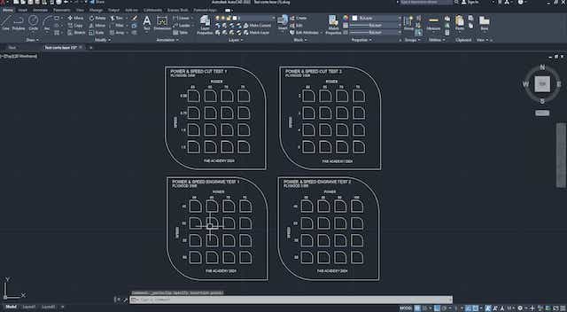
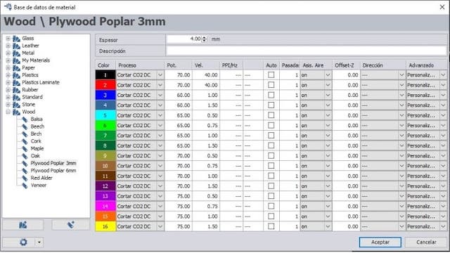
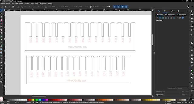
After, we export to INKSCAPE to be able to place the respective colors on each frame that is composed according to the power and speed. Different colors will be used so that the laser cutter software can read and we can configure the power and speed according to the settings we have in the software.
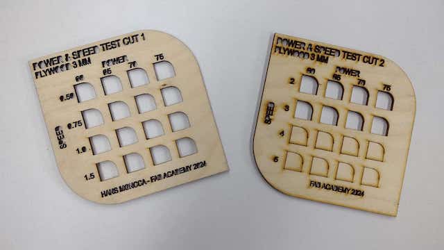
First we started working with PLYWOOD where we configured heir respective values for each board to see the difference between them in cutting and engraving.
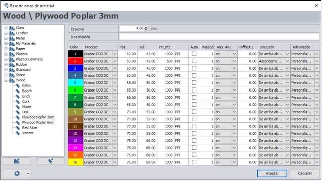
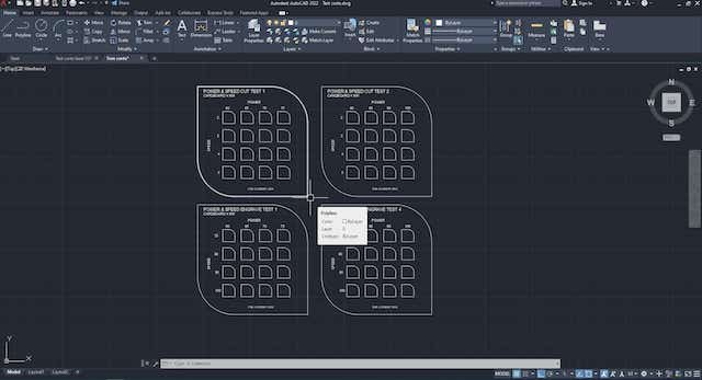
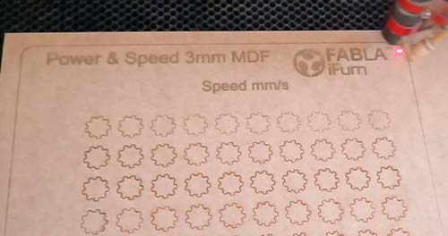
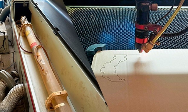
After configuring each value table, we can see the results of the laser cutting and engraving in each of them. At first, we had problems with the scale since the board was very small and the letters did not come out well. So we had to enlarge the tables and configure everything again. Here is a photo of the first test.
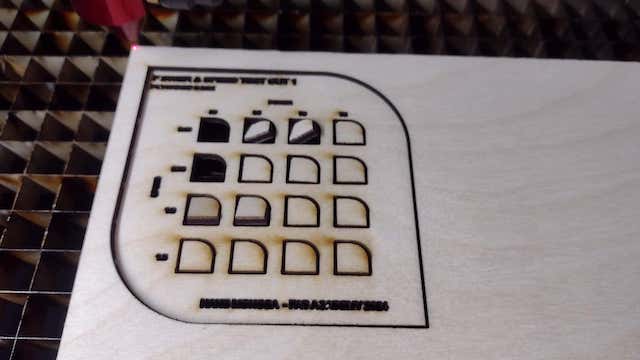
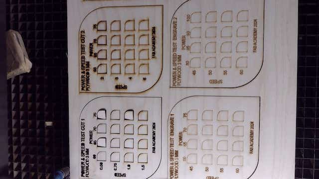
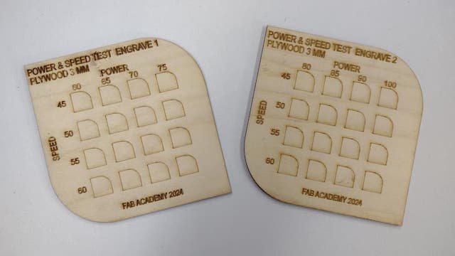
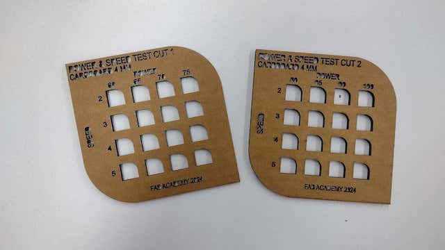
After changing the entire table configuration, we started cutting again and this time it turned out the way we wanted. It can be seen that the tables now do not present errors and the data is visible.
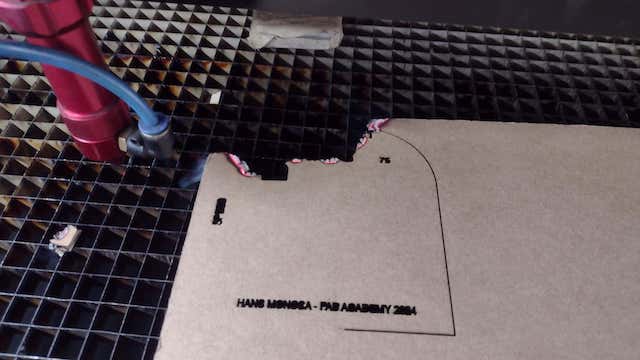
Now we start working with the 4 mm CARDBOARD where we configure their respective values for each board to see the difference between them in cutting and engraving.
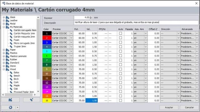
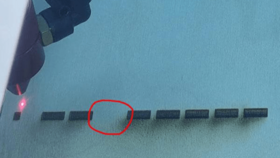
Here we had a problem, when cutting with these laser power and speed characteristics, suddenly we started to smell smoke and the cardboard was on fire. The very slow machine and the very high power meant that the cardboard caught fire, here is proof of it.
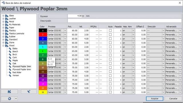
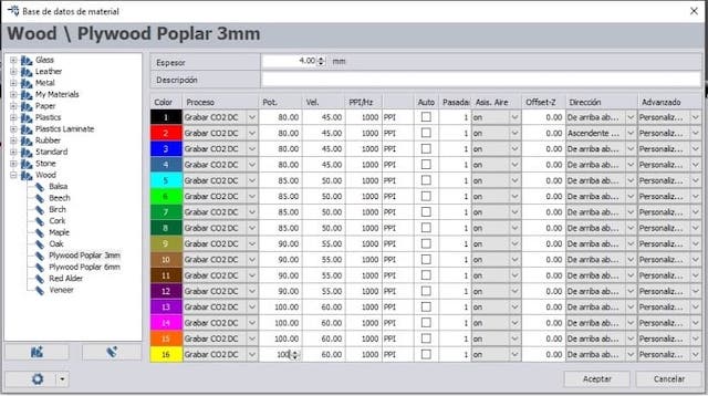
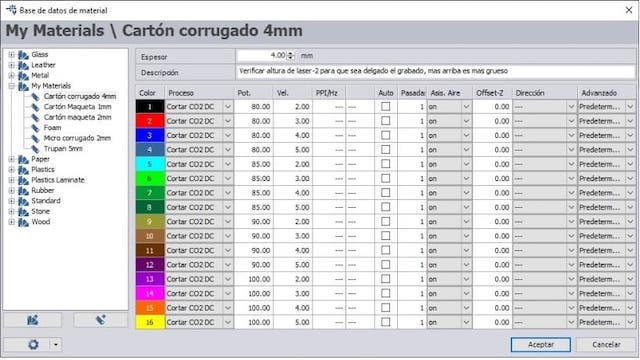
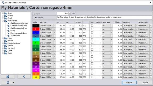
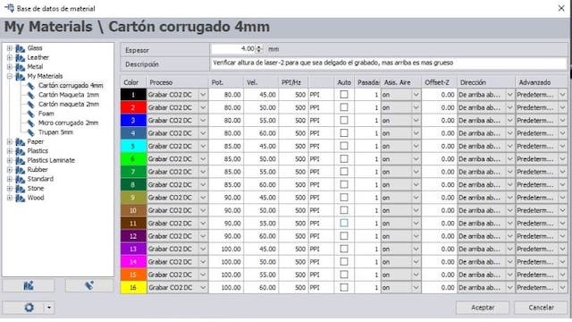
So we had to change all the board settings and increase the speed further to avoid fires in the FAB LAB. So now I show you the screenshots of the values that were used for the 4 mm CARDBOARD.
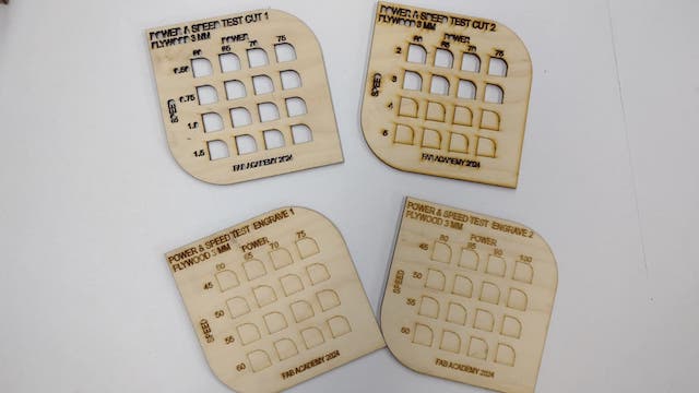
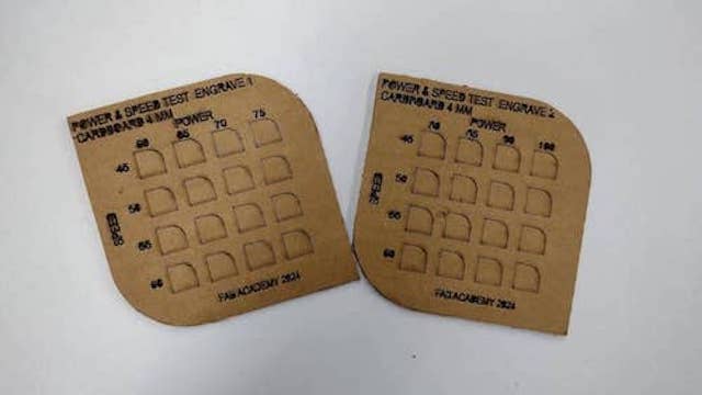
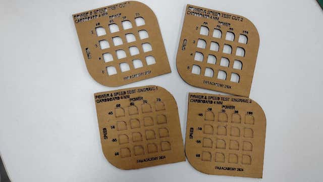
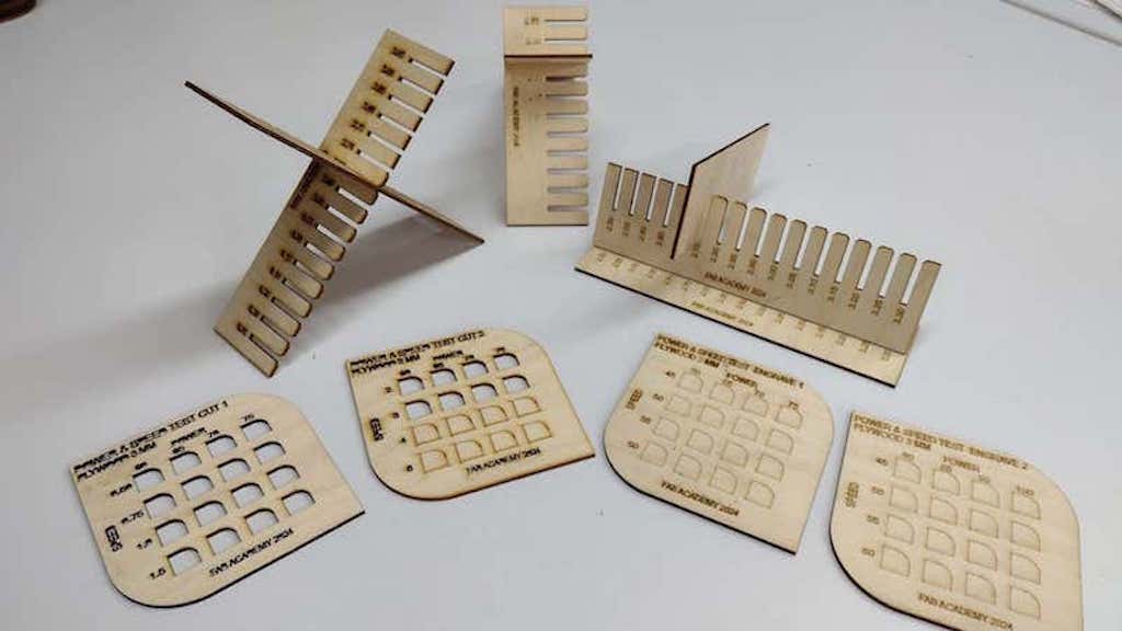
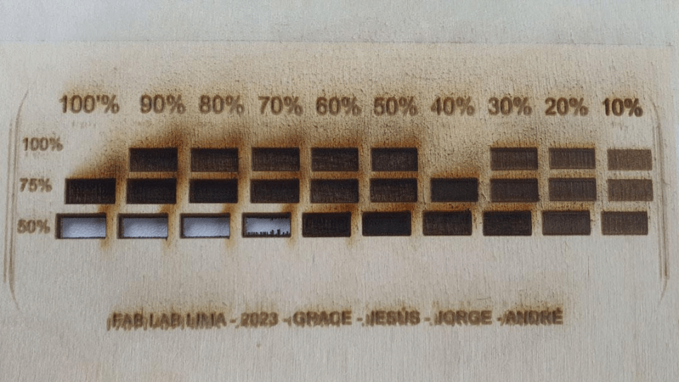
After having all the configuration ready, we proceed to cut and engrave each table according to the characteristics and values indicated. Here the results:
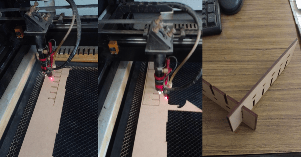
STEP 3: PRESSURE TEST AND KERF
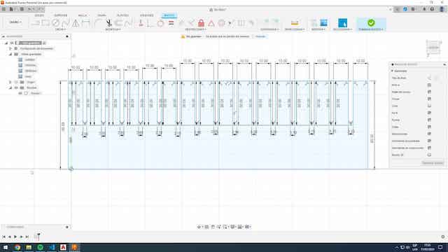
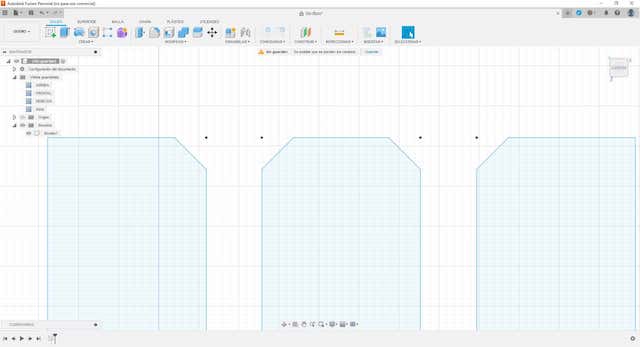
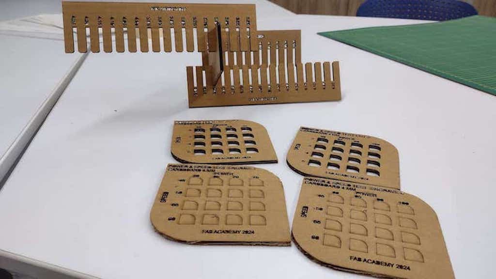
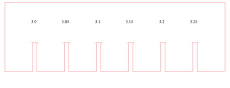
Now we will do the pressure test of cardboard and plywood. To do this, we design the piece with FUSION 360, where we make a template with several sockets of different sizes. The actual measurement of the cardboard is 4 mm and the plywood is 3 mm. Now we will make “the comb” that goes a few millimeters more and less according to the width of the material to find the exact width to achieve the pressure of each material.

After having all the configuration ready, we proceed to cut and engrave each table according to the characteristics and values indicated. Here the results:
Let's remember that we have to make a “CHAMFER” in the corners so that when testing the pressure and the kerf, the material is not damaged and the tips are not damaged quickly. For this reason, it is advisable to make a “CHAMFER” in the corners.
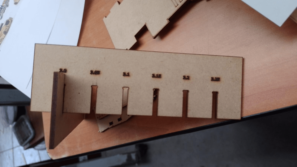
RESULTS
Here I show the achieved cut of the KERF of the laser cutter to know the true adjustment of each material and thus be able to carry out the following assignment of the parametric design.
Result 1
Result 2
Result 3
Result 4
CONCLUSIONS
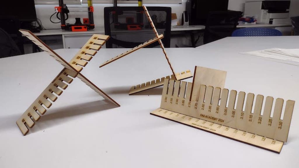
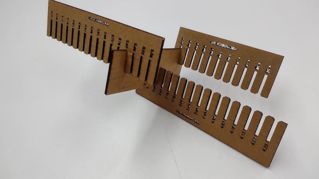
There were some problems with the KERF tests since we had problems with the engraving mainly of the section numbers and therefore we had to laser cut several “COMBS” but in the end we were able to find the fit of each material. Where we can conclude that:
Actual plywood thickness: 3.00 mm - actual fit: 2.75 mm = PLYWOOD cut: 0.25 mm
Actual cardboard thickness: 4.00 mm- actual fit: 3.65 mm = CARDBOARD cut: 0.35 mm
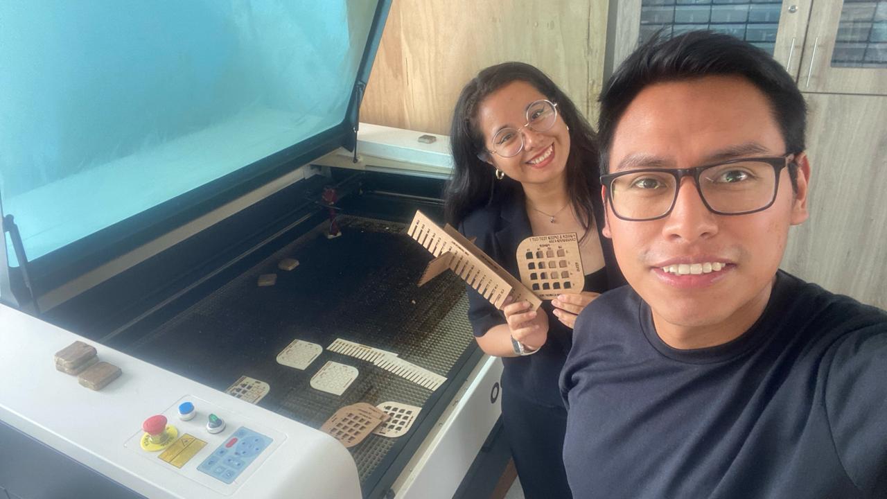
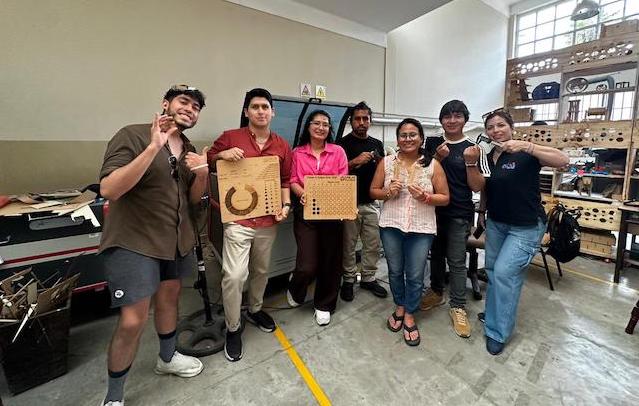
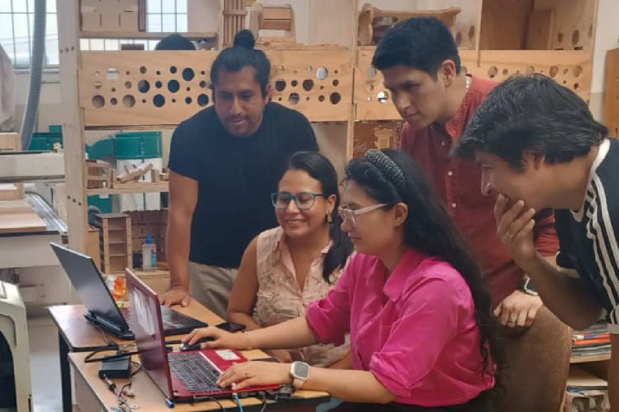
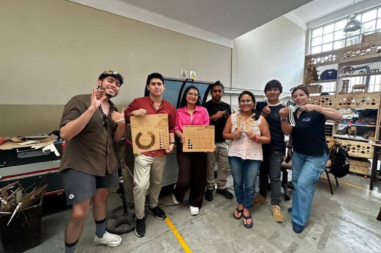
Here are some photos of the group work with my friend Maryori, where it was a day of learning, with mistakes and successes to achieve the grupal assignment.
FILES
Group 2:
- Cristian Loayza
- Silvana Espinoza
- Maria Angela Mejía
- Jesús Lucero
- Ronal Vilca
Cristian Loayza
We will start with the group assignment: characterize your laser cutter's focus, power, speed, rate, kerf, joint clearance and types.
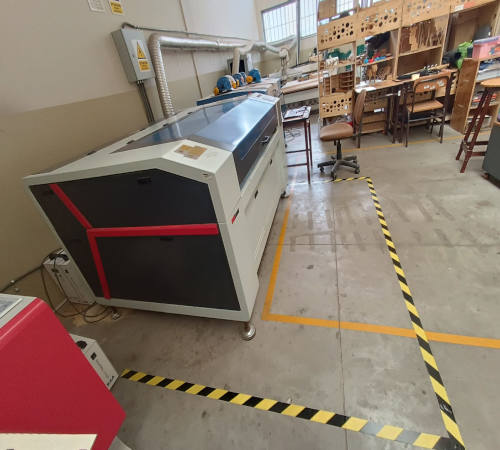
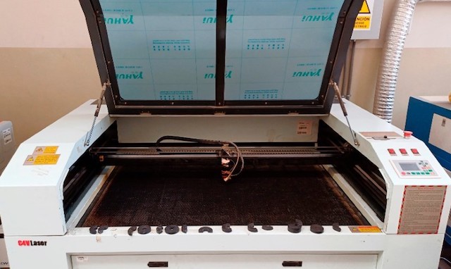
The C4V Laser
The laser cutting machine we will use in this assigment is the C4V Laser which allows us to cut, mark and engrave non-metallic materials up to 15mm thick.
The brand is C4V Laser
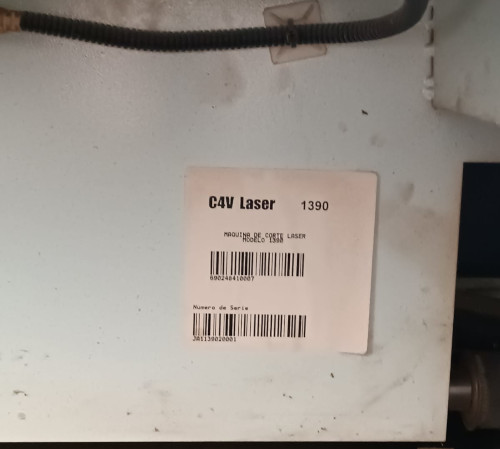
The model is 1390
Working area 1300*900 mm.
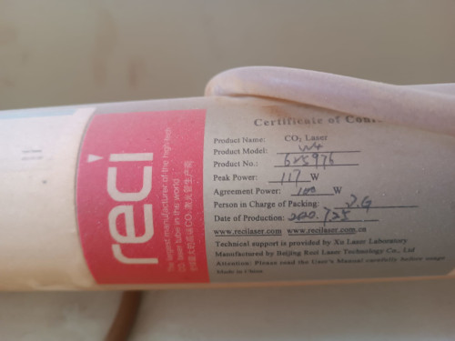
Laser Source reci CO2, agreement power 100 watts
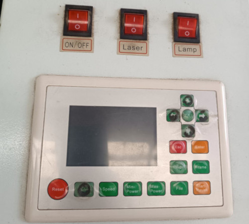
Display Panel Mainboard
RD Works software controller V8.01.54
Safety
The work area around the laser cutting machine is delimited, and there are informative signs and warning stickers in different areas of the machine.
Safety area
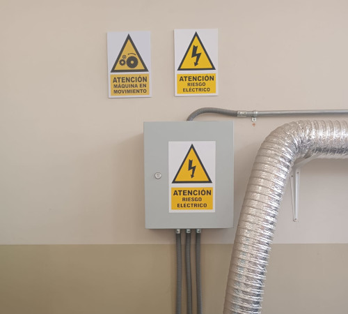
Informative safety signs
Tools
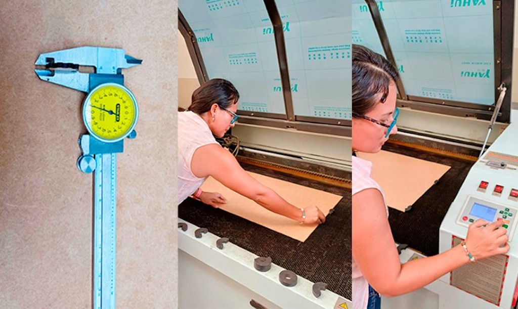
To work with the laser cutting machine, we must have at hand a series of tools such as a tape measure, a caliper, magnets to hold the materials, etc.
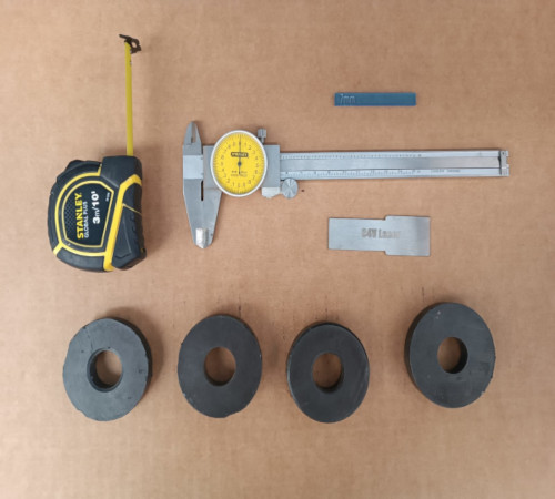
Basic tools
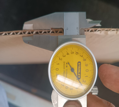
Material thickness gauge
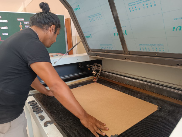
Group testing
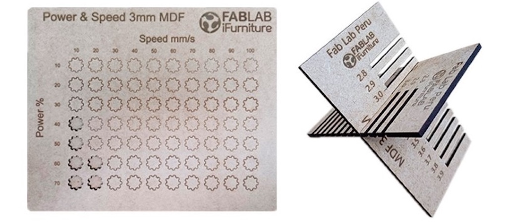
In this group test we will perform a cutting test with parameters of power in % and speed in mm/s, the material for this test will be MDF since it is the material found in the fablab.
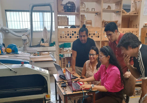
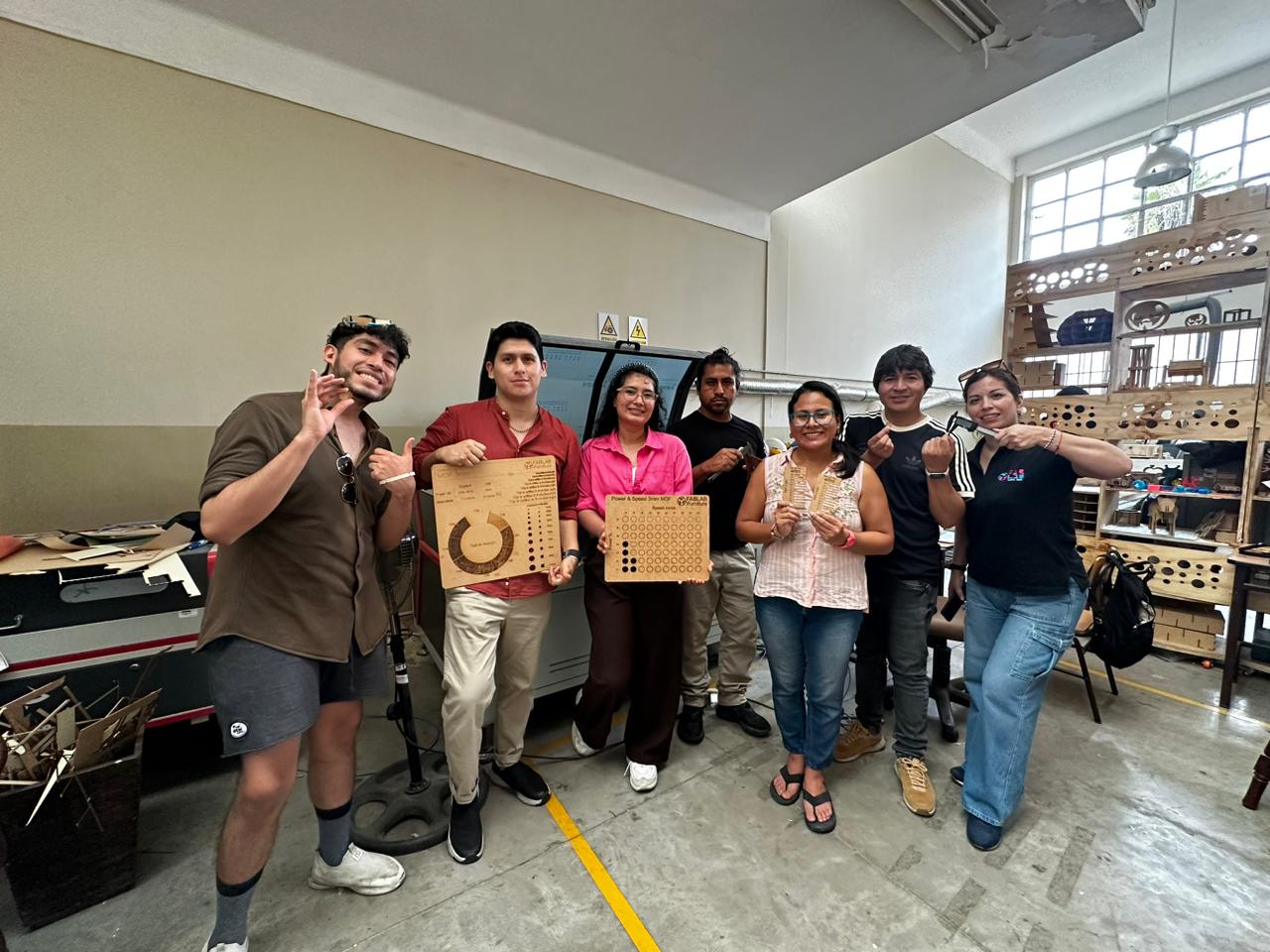
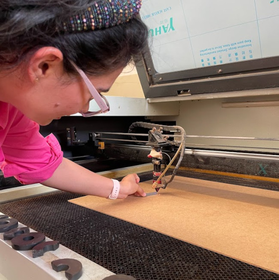
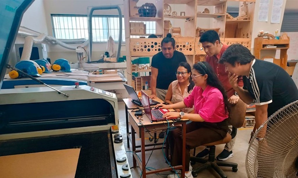
Working the group assignment
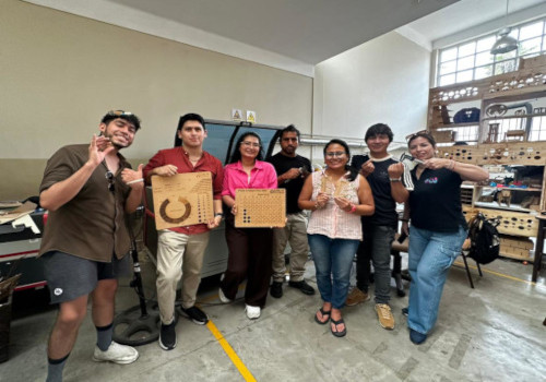
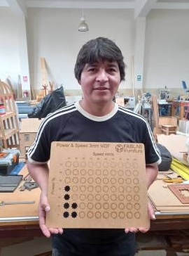
Happy for the results
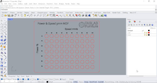
Designed in Rhinoceros and exported to dxf
We set the different parameters to use
test 1
test 2
Result 1
Result 2
Silvana Espinoza
This week we were very united to do our homework for the week, I love my team.
The C4V Laser
The laser cutting machine we will use in this assigment is the C4V Laser which allows us to cut, mark and engrave non-metallic materials up to 15mm thick.
Feb. 9
In the group project we met at the ifortunity fablab where my teammates and I did laser cutting tests. The first thing we did was select a design for the
cutting tests, taking into account the power and cutting speed. For this, we used a table that our partner Cristian had to later in RDWord be able to set
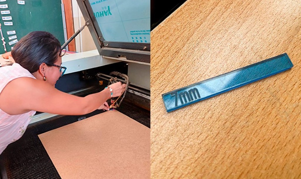
the power and speed of each shape. After that we saw the model of the laser cutter, we saw that we had to calibrate the laser cutter and in which we used
a 7 mm strip of acrylic to be able to calibrate the laser to the work table in which after being well calibrated we proceeded to send our file to make the
cut first we made the first line the first row of our test then the second realizing that we still do not He made no cut the third
fourth, with 40% power and 10% speed, the cut was made, then the fifth line with 50% power and 10% speed was already developed. The cut was developed, I saw that
from 40 speed onwards it was no longer possible. I made the cut with these selected figures, now I will do other tests but with squares to be able to check if these gear shapes have an impact on the cut.
Feb. 10
Characteristics of the C4V model 1390 laser cutter. With C02 laser tube.After reviewing the characteristics of the laser, we moved on to calibrate so that our tests are correct, then we took a 7mm rectangle that we placed between the laser and the work
table to be able to calibrate and began to move it, everything was fine when finished, and with The designs we developed began to do the tests,
first we only reached 70% power for the cut, since some in the team had experience in laser cutting and told us that probably more of it could burn, after making the cutting table ,
I had designed a measuring comb to see the laces and what measurement was correct.
Our file was designed by our colleague Cristian, who made an interesting shape for the tests,
then our instructor Luis told us that we should try square shapes for cutting to see differences
or compare the speed in complex shapes than in straight shapes.
That means I'll do it again.
Today
I had a review by my instructors from the fable Peru in which they advised me to make the cutting board again in which my instructor Luis told me that it would be better to do it in square shapes since in the gear shape it could be that because of the curved shapes that have varying speed and power,
so he gave me his website so I could review the files he used for his cutting to guide me. In my designs I am going to make the cuts again in 3 mm MDF, also laser engraved in acrylic and I am going to test the comb again since, as I had mentioned before, I did it straight and now I am going to test the comb with the tips edged
Laser cut design and Cutting result
Testing a laser machine is important to ensure that it is operating correctly and that the settings are appropriate for the specific material and job.- Power and Speed Adjustment: Determine the optimum power and speed settings for the specific material you are using. our first group task.
- Verify Focus: Ensure the laser is focused properly for accurate cutting and engraving.
- Engraving Tests: Perform engraving tests on different materials to evaluate quality and adjust settings as needed.
- Verify Accuracy: Perform cutting tests on precise patterns to evaluate machine accuracy.
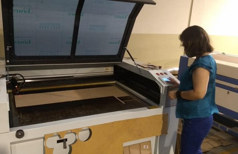
Calibrate the laser machine
Basic Calibration of a Laser Cutter: Laser Focus Adjustment:- Make sure the work table is level. Adjust the height of the table or laser to achieve optimum focus on the work material. Checking and Adjusting Mirrors
- Verify that the mirrors are clean and properly aligned. Use a laser marker or laser pointer to ensure that the beam is properly reflected from each mirror to the cutting head. Cutting Head Alignment
- Align the cutting head so that it is perpendicular to the work surface. Adjust any misalignment to ensure accurate cuts. Power and Speed Calibration
- Perform cutting tests on reference materials to adjust power and speed according to your needs and material type.
7mm gauge to use as a reference for laser cutting machine.
Placing the 7mm gauge between the laser and the cutting table
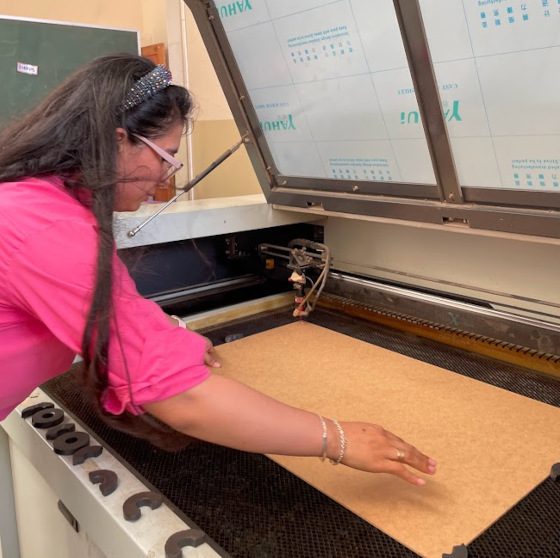
Correctly arranging the MDF cutting material so that all sides
Maria Angela Mejia
To complete the group work, I went to the Fab Lab iFurniture which is located within the Meliton Carvajal Emblematic Educational Institution, in Lince district, in the city of Lima, Peru.
General Instructions
Important
How to Use a CO2 Laser Cutter
To use this laser cutter you must:
- Check the environment. This must be free to walk, without danger of tripping over any cables.
- Select the material you will use, place it on the cutting surface and manually calibrate the nozzle. Use the caliper.
- Configure the cutting parameters in the RDWorks program.
- For each new material to be used, the power/speed test must be carried out to find the best cutting parameter.
- The comb test should also be performed to find the necessary kerf for the selected material.
- Make sure you have good ventilation in the space, as well as that the extractor is operating correctly so that no smoke comes out when the cutting begins.
- When the work is completed, remove the material and verify the cut.
- When you leave Fab Lab iFurniture, leave the space the same or better than how you found it.
Placing the calibrator
Correctly arranging the MDF cutting material so that all sides
Final Test Result
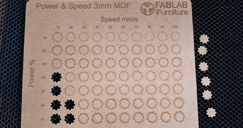
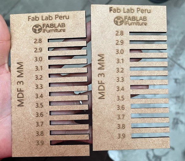
According to the test carried out, the parameters that were able to successfully cut the pieces were 40 power / 10 speed, 50 power / 10 speed, 60 power / 10 speed, 60 power / 20 speed, 70 power / 10 speed and 70 power / 20 speed. According to the comb test for 3mm MDF, the joint that works best is the 3.1mm one.
Conclusions
Working with my Fab Academy colleagues for the first time in person was very interesting. Each one shared their digital manufacturing experiences and we spent a nice friday afternoon.
Ronal Vilca
For the development of the group project corresponding to week 3, focused on "Computer Controlled Cutting".
I organized a trip from Huanuco to the city of Lima. The main objective of this visit was to carry out the detailed characterization of various parameters of the laser cutting machine, such as focus, power, speed and purpose free space of the joints.
These aspects were fundamental for the correct execution of our project.
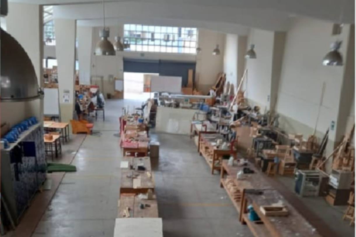
During my stay in Lima, I had the privilege of working at the Fab Lab iFurniture facilities.
It was an enriching experience, as the FabLab iFurniture team welcomed us and gave us full access to their resources, including the laser machine needed for our collaborative work.
The opportunity to test and work as a team in such a collaborative and well-equipped environment was invaluable to the success of our project.
I take this opportunity to express my sincere gratitude to Fab Lab iFurniture for their generous hospitality and willingness to collaborate.
The collaboration between Fab Lab iFurniture and Fab Lab Peru demonstrates the spirit of community and cooperation that drives the movement of digital manufacturing laboratories throughout the country.
I am grateful for the opportunity to participate in this unique experience and for the lessons learned that will undoubtedly enrich our future projects at Fab Lab Peru.
We have focused on two fundamental aspects:
- 1. Teamwork to test the laser machine, adjusting the cutting speed and power to obtain optimal results.
- 2. The development of personal work with parametric design.
This combination has allowed us to not only experiment with laser technology, but also explore our individual creative abilities.
Describing the Laser machine
The aim is to provide detailed instructions for making computer controlled cuts using the C4V LASER 1390 laser machine. Cutting parameters including speed and power as well as calibration of the laser head with respect to the 3mm MDF material will be covered:
Previous requirements
Before you begin, make sure you have the following items:- 3mm thick MDF material.
- Computer with laser machine control software installed.
- The refrigeration chiller is connected.
- The smoke extraction system is connected.
- Calibration tools such as: Bernier, 7mm cut material for height measurement.
Procedure
Laser Head Height Calibration
- Make sure the machine is off/static before making any adjustments.
- Place the 3mm MDF material in the laser machine.
- Adjust the height of the laser head using the calibration tools provided until it is 7mm away from the material.
- Check the distance carefully to ensure accurate calibration.
- Turn on the laser machine and make sure it is connected to the computer with the control software open.
- Use the designed die to make cuts in the MDF material,with speed parameters from 10 mm/s to 100 mm/s and powers from 10% to 70% respectively.
Identification of Cutting Parameters
Take these recommendations into account.
First test
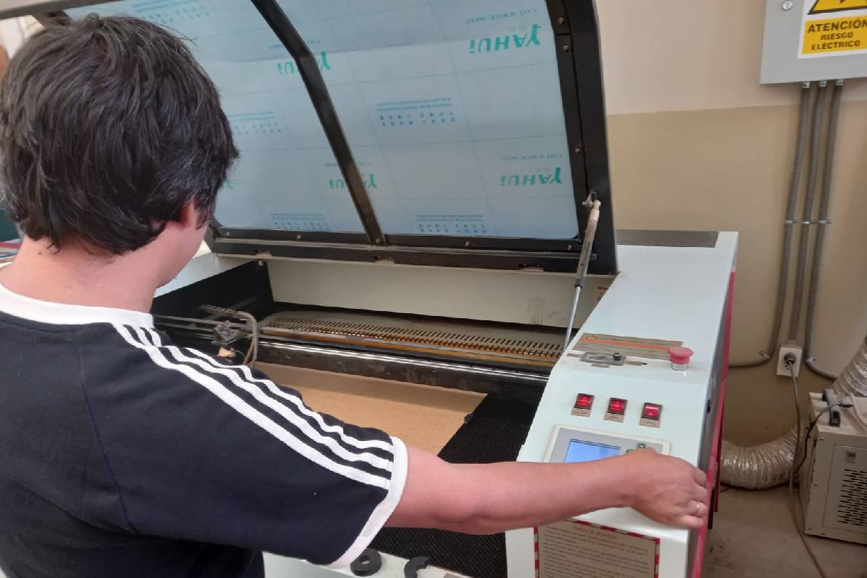
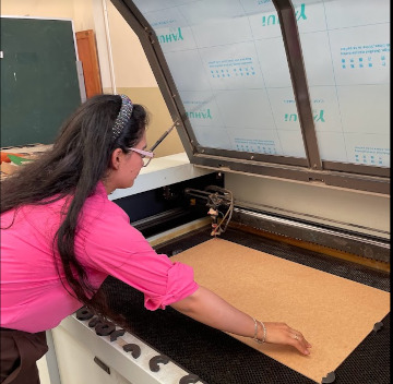
Locating the machine
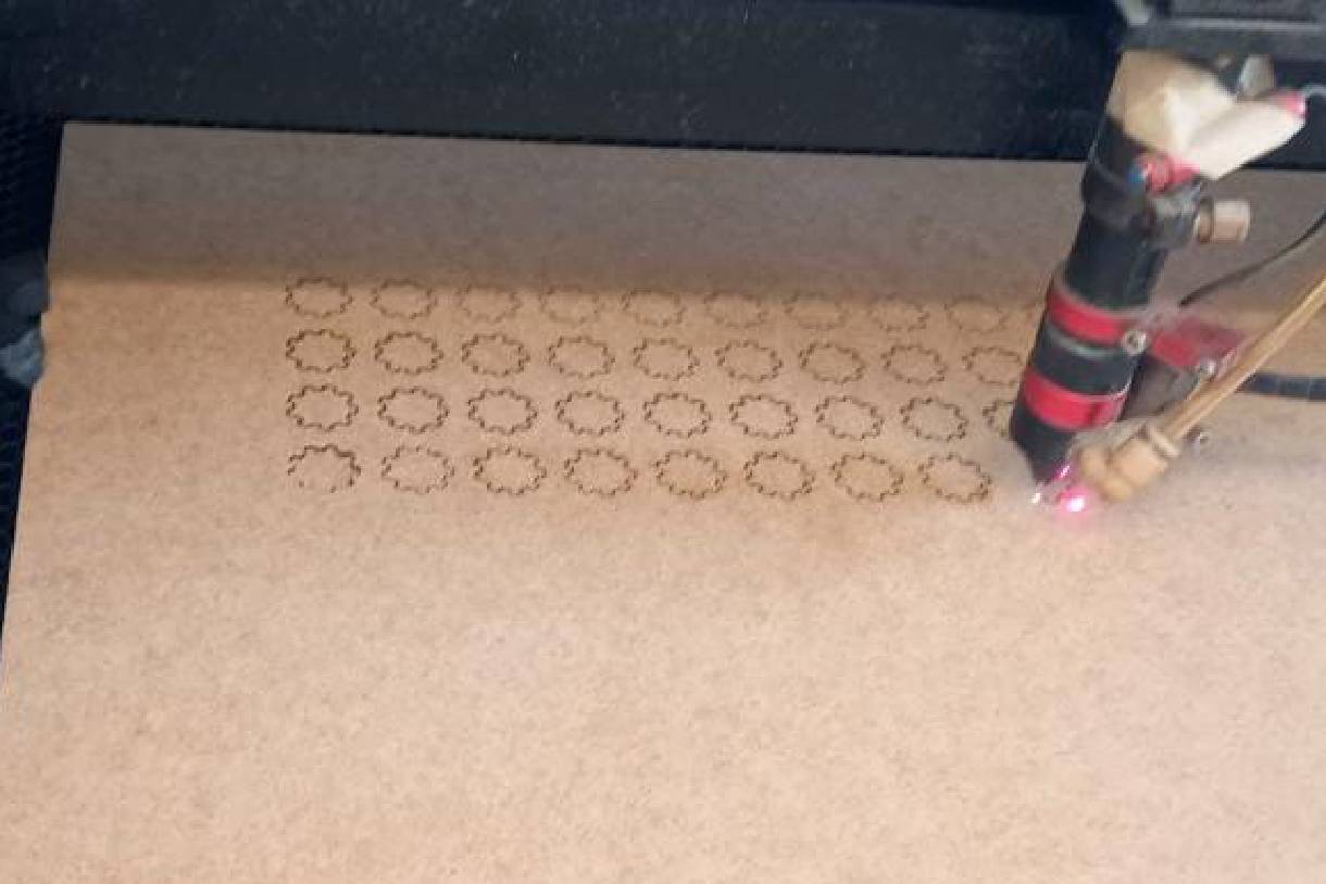
Cutting tests
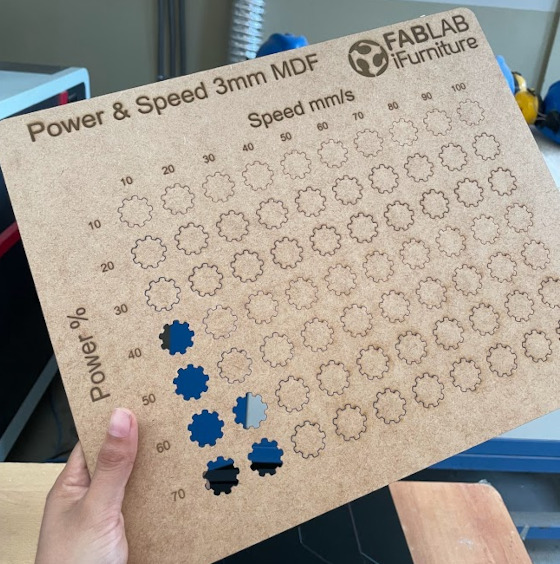
Carrying out a complete die process, varying both speed and power from minimum to maximum values, allowed us to understand the relationship between these parameters and their effect on the cutting process.
It was observed that, within the range tested, the optimal combination of speed and power to obtain clean and precise cuts in 3 mm thick MDF material was 10 mm/s with a power of 60%.
This was the result of the first test carried out with the C4V laser 1390 machine.
Second test
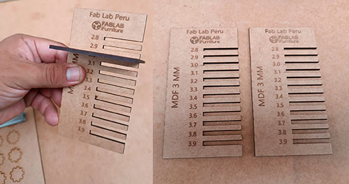
In addition to our initial tests, we decided to perform a second evaluation focused on the coupling between two combs.
This research phase is crucial to ensure the effectiveness and precision of our products in practical applications.
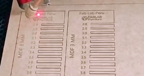
To carry out this evaluation, a comb was designed with specific cuts of various dimensions: 2.8 mm, 2.9 mm, 3.0 mm, 3.2 mm, 3.4 mm, 3.6 mm and 3.8 mm.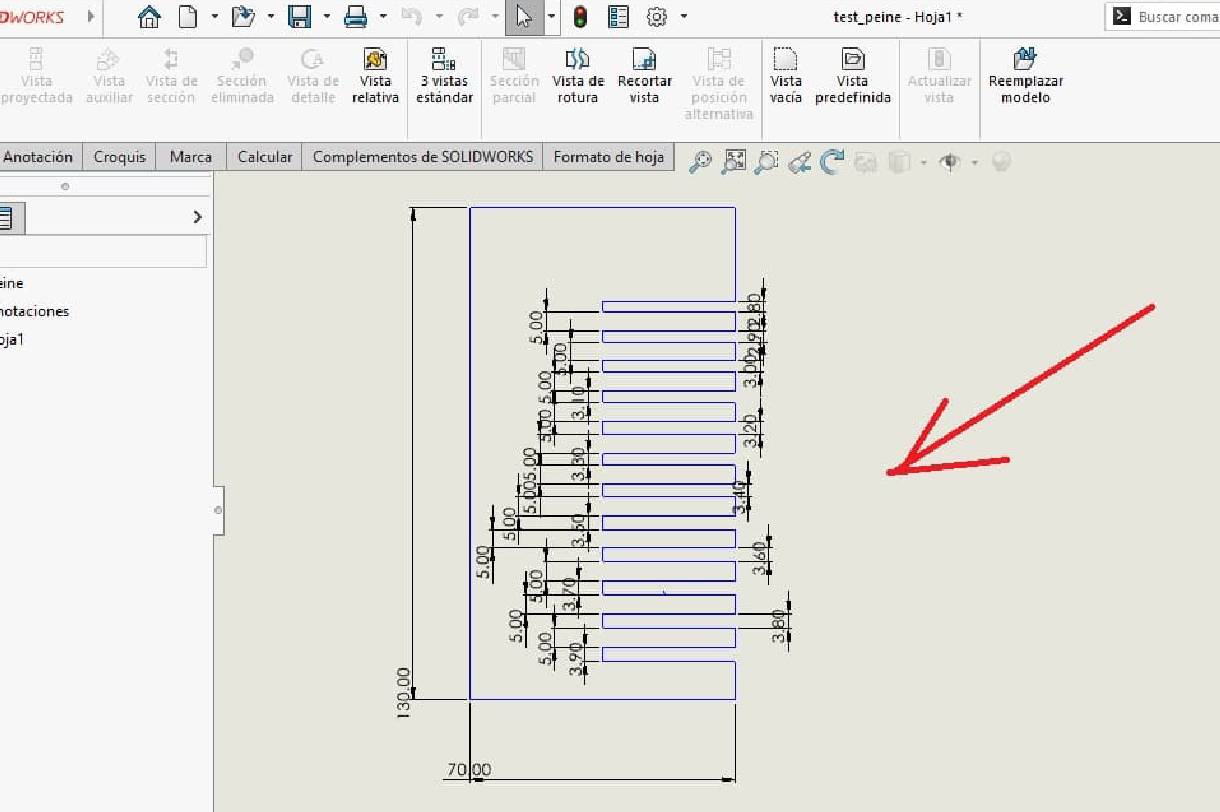
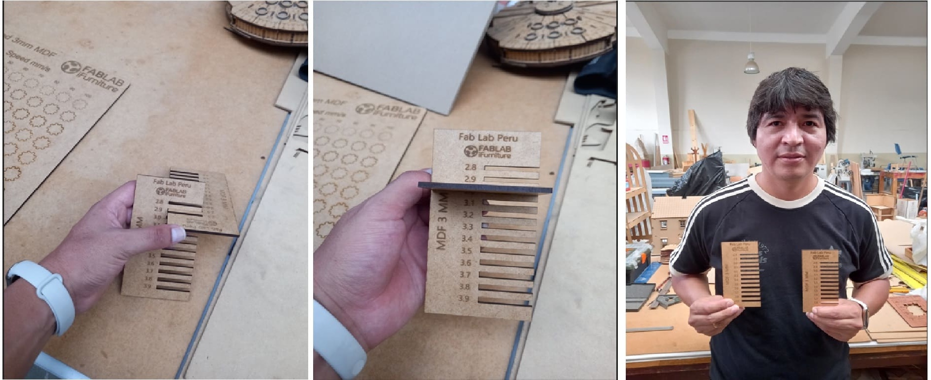
During the testing process, special attention was paid to details such as coupling stability, resistance to deformation and consistency under different loading conditions.
These criteria allow us to evaluate not only the effectiveness of the coupling in terms of physical fit, but also its ability to withstand adverse conditions and maintain its functionality over time.
Summary
Group 3:
- Renson Samaniego
- Wilber Giron

Group 4:
- Grace Schwan
- Jorge Pazos
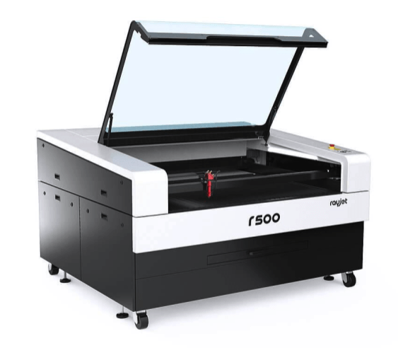
For this group assignment we use the laser RAYJETr500 CO2 pantograph for simple laser cutting and engraving.
| WORK SURFACE | MACHINE SIZE | LASER POWER | LASER TYPE |
|---|---|---|---|
| up to 1300 x 900mm | an 1550 x al 1080 x prf 1080 mm | 60 a 100 W | Láser de CO2 |
| - | an 1870 x al 1700 x prf 1110 mm | 60 a 120 W | Láser de CO2 |
| PROCESSABLE MATERIALS | CUT | ENGRAVE |
|---|---|---|
| Advertising articles | X | X |
| Advertising articles | X | X |
| Leather cut | X | X |
| Dřevo | X | X |
| Metals | X | X |
| Paper | X | X |
| Plastics | X | X |
| Pohárů | X | X |
| Seals | X | X |
| Signaling | X | X |
| Textile | X | X |
| Glass | X | X |
Technical Data:
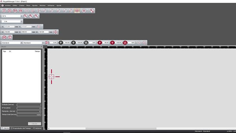
We used the Focus Tool and set the value to 2 as recommended by the Trotec expert.
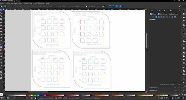
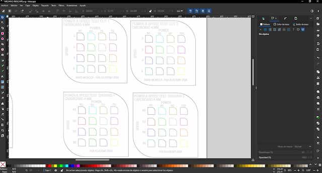
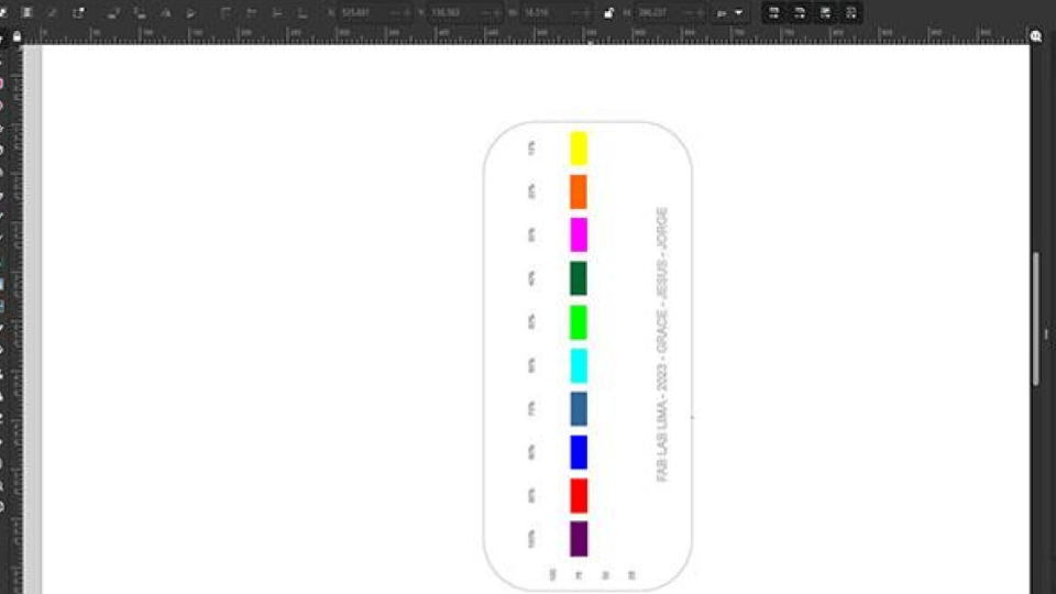
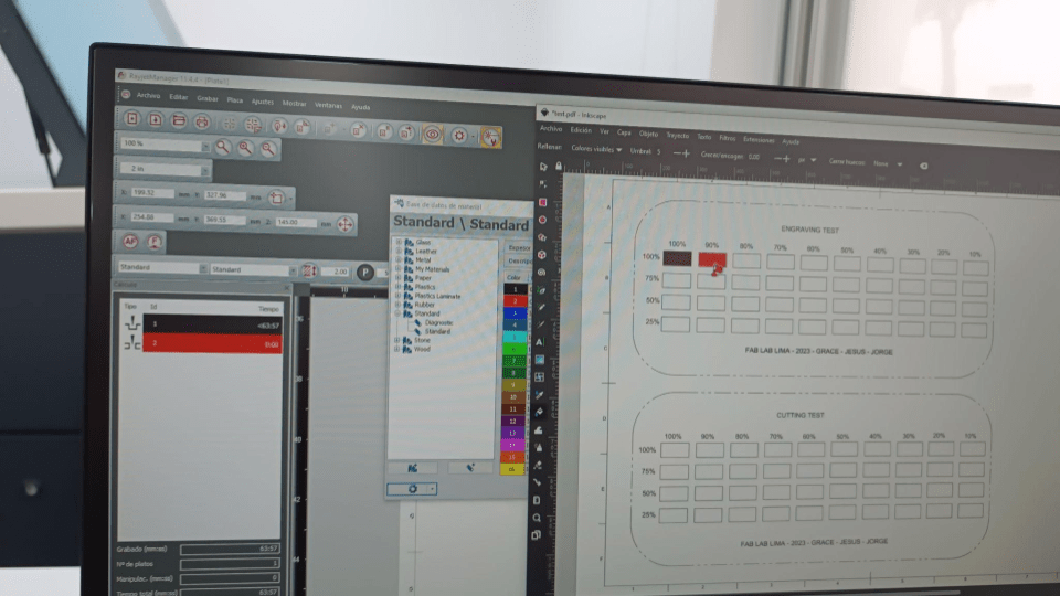
In Autodesk Fusion 360 we create a test layout that features squares with different power and speed values. Since the native Rayjet program does not accept dxf files, we exported the file to Inkscape to assign the colors to each square.
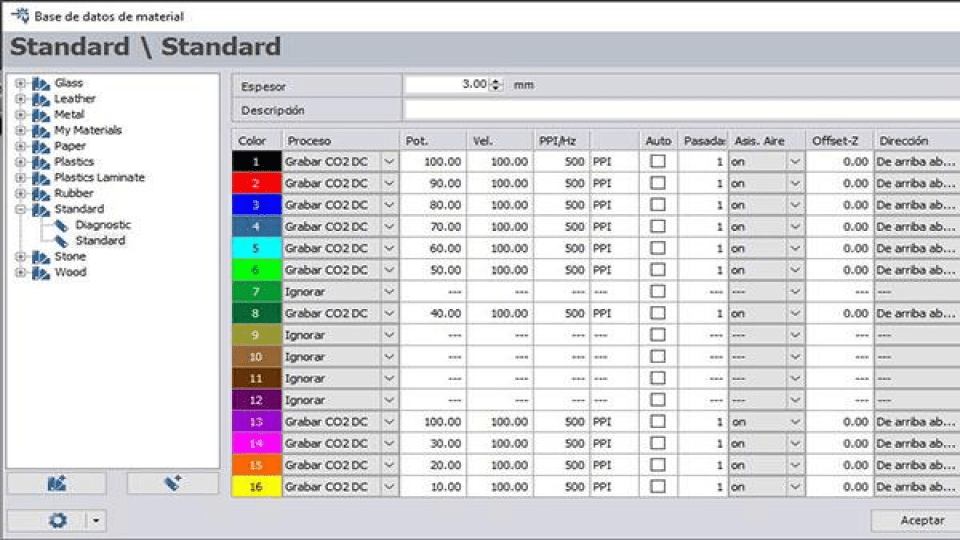
To export to Rayjet Manager, we send the file to the printer named Rayjet Manager.
There was a problem with the machine recognizing the yellow layer (corresponding to 80% power) and this engraving setting did not plot, so I assigned another color to this setting.
We then corrected the RVB values and blended the colors so they could all be recorded.
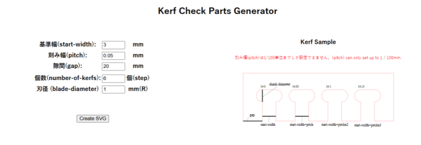
Kerf Check Parts
I found a very interesting fab Academy page to be able to generate my cutting clearances and joints test on the page of Atsufumi Suzuki, Fablab kamakura graduate in 2022. Kerf Check Parts Generator
Here is the hero photo of the board rule:
You'll find the board rule file here