3. Computer-Controlled Cutting
Weekly Highlight (February 7 to 15)
-
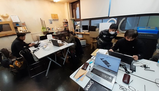
Muhammad Jidda of FabLab Abuja, Nigeria, joined us at FabLab Kannai. He is going to stay with us for three weeks until the end of February.
-
We worked on the first group assignment. Hajime Ito and I formed a team and jointly worked on the assignments of the week. For the summary of the assignment, please check Group Assignment Week 3 at the FabLab Kannai Fab Academy site.
-
Made mobile phone stands as my parametric construction kit by laser-cutting. But didn’t spend too much time for ideation and I jumped at the idea with quick and easy design. Need more practices.
-
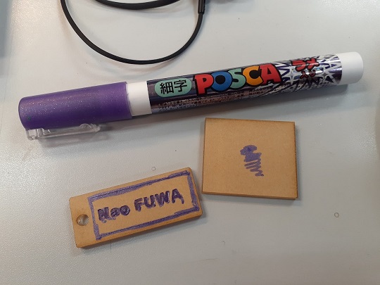
Didn’t spend much time for design for vinyl-cutting. However, marking my glass with sandblast and stamping on my diary with gold foil were our unique experience with the machines available in our lab.
Assignments Overview
Here is the list of individual assignments given by the instructors. As for the Group Assignment, please see the Group Assignment page on the FabLab Kannai website:
- Design, lasercut, and document a parametric construction kit,
  accounting for the lasercutter kerf, which can be assembled
  in multiple ways, and for extra credit include elements that aren’t flat.
- Cut something on the vinylcutter
Learning about Laser-Cutting Operation
Before the Global Session on February 7, we had a chance to operate the laser-cutter at FabLab Kannai, which is equipped with Universal VLS Desktop VLS2.30 with the power capacity of 30W and the maximum cutting area of 406.4mm by 304.8mm. Plus, I had the past experience in operating the same model at another makerspace in Tokyo and Trotec Speedy 300 at FabLab CST.
1. Safety: Before we directly jumped at the laser-cutting operation, we were reminded by our instructor of the following safety measures. These were also reminded by Prof. Neil in the last global session:
(1) Stay close to the machine while you are running it.
(2) Check the location of the fire extinguisher, which should be located close to the machine.
(3) Be sure to turn on the exhaust system and the compressor before you start the cutting operation.
(4) The materials that produce toxic gas and corrosive gas are strictly prohibited for laser-cutting.
(5) Do not stare at the flash light.
2. Data Preparation: We are supposed to prepare the 2D design data with our own PC and import it to CorelDRAW X6 at FabLab Kannai. In our exercise, we prepared the design with CorelDRAW and, using the “Print” command of the CorelDRAW, we called the Universal Control Panel (UCP). We must keep in mind the maximum size of the cutting. Also, we have to complete all the definitions for the lines and infill. Here is the basic coloring principles:
Black: For engraving raster data.
Red: For cutting on vector data.
Blue: For marking on vector data.
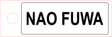
I forgot to save the design data I made with CorelDRAW in our exercise. Therefore, just for the review and for the familiarization to the design with Inkscape, I prepared the same design of the key tag with Inkscape as attached herewith.
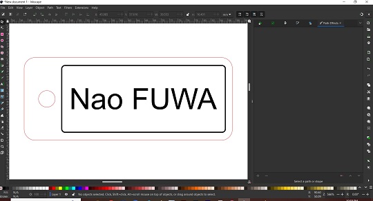
JPG: Key Tag
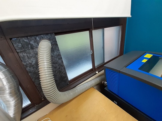
3. Switches On: First, we had better make sure that the air duct for the exhaust system is put in the right place so that it could discharge dust and odor outside.
In the case of the laser-cutter at FabLab Kannai, there were four switches to be turned on before the machine is ready for cutting: (i) Voltage Transformer for Laser-cutter; (ii) Voltage Transformer for the Exhaust System; (iii) Exhaust System itself; and (iv) Laser-cutter itself. As for the switch for the laser-cutter, we were told to switch on with the power button on the UCP on the laptop.
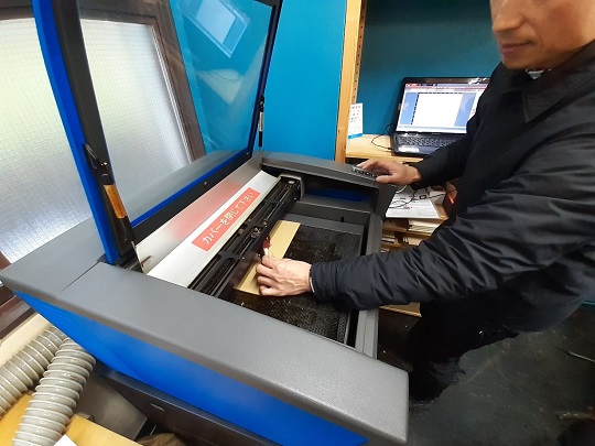
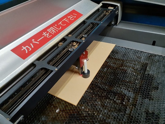
4. Setting the Cutting Procedure: Once the laser-cutter is switched on, I opened the cover and placed the acrilyc board on the cutting table. Then I did:
(1) Focus: Activate the pointer by clicking the focus icon on the UCP. Move the pointer to the place where you want to cut. Place the focus tool on the acrilyc board. And then, by pushing up or down key of the laser-cutter, make adjstment of the distance between the focus carriage and the material.
(2) Placement of the Design: Click the replacement icon on the UCP. Drag the design to the place where you want to use the material for cutting.
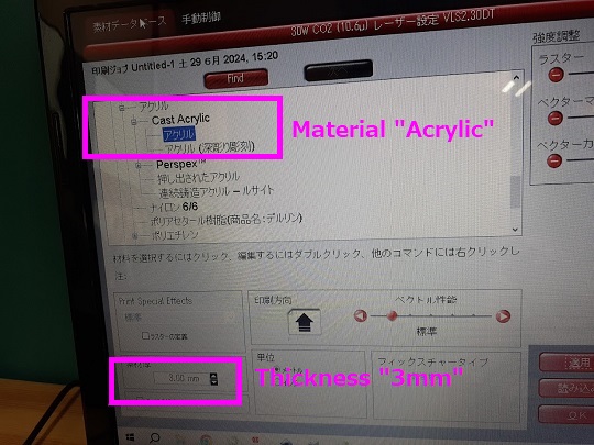
(3) Setting Parameters: Click the setting button on the UCP and then a new window will be popped up. First, click the “Material Database” tab and choose the material type and thickness. Second, click the “Manual Control” tab and set the parameters (Power, Speed, PPI (pulse per inch), and Z-axis) for each of the colors to be used. You have to finish the parameter setting for every color by cliking “Set” button. PPI means how many laser pulses per inch are used for the engraving.
The best formula for the laser-cutter in the local lab is subject to the Group Assignment of the Week3. However, for the first test cutting, I used a 3mm acrylic board as a material. Therefore, here I applied the pre-set parameter sets for 3mm acrylic board and proceeded to cutting.
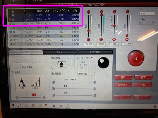
Parameter Setting
| Color | Data Type | Laser Power | Laser Speed | PPI |
|---|---|---|---|---|
| Black | Raster | 29.0% | 100% | 500 |
| Red | Vector | 100% | 4.8% | 1000 |
5. Cutting: Before clicking the “Start” button on the UCP, need to recheck focus and the exhaust system. Once it starts the operation, you should stay close to the machine. After the cut, keep the cover closed for a while until all the dust and odor are vacuumed.
6. Switches Off: Switch off the machine itself by clicking the “Power” button on the UCP. Then switch off the exhaust system and then the voltage transformers. Clean up the area. And never forget about the periodical maintenance and clean-up.
Design Data for This Exercise: PNG / SVG
Parametric Construction Kit Design with Fusion360
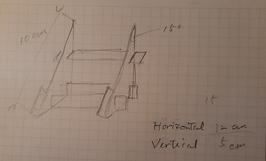
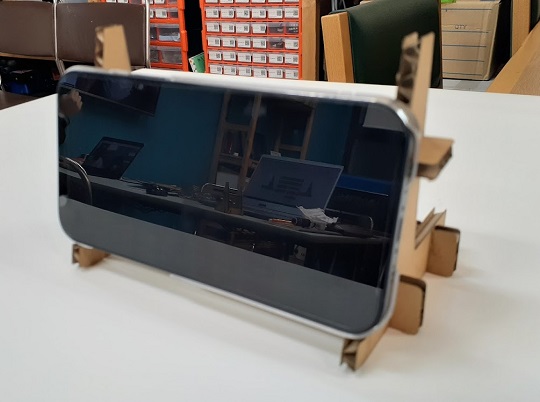
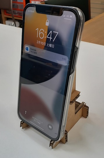
For this individual assignment, I have decided to design a phone stand that could be adjustable to horizontal and vertical placement of the mobile phone, by changing the horizontal bar sets:
1. Recap of the Parameters: To begin with, through our Group Assignment to characterize our laser-cutter’s kerf and joint clearance, we got the following parameters:
Thickness of the cardboard: 5.13mm
Kerf: 0.17mm
Joint Clearance: 0.2mm
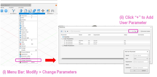
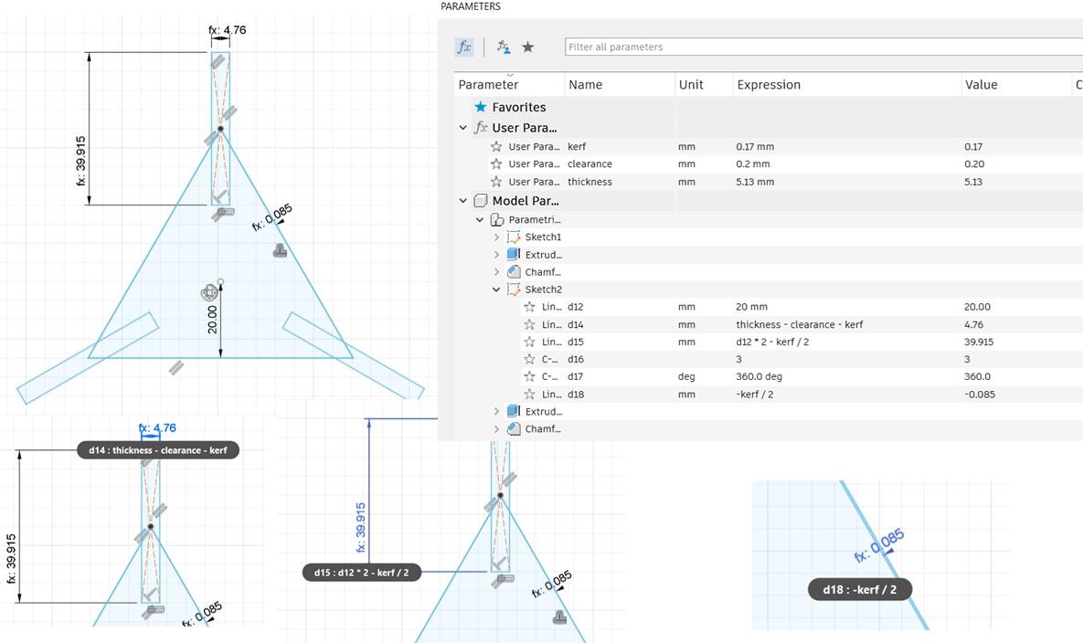
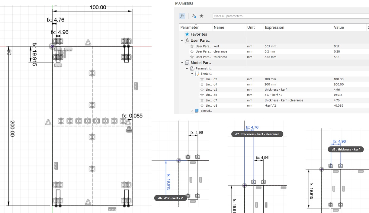
2. Define the User Parameters: Open Fusion360 and from the “Modify” menu, choose the “Change Parameter”. A new dialogue window “Parameter” is popped up. Then by clicking “+”, you can define your new parameters in advance.
3. Sketches: Then you could start the sketches. After drawing the outline of the parts, you could proceed to drawing the joints. Using the sketch dimension, make the formula by combining the parameters you defined in 2. above.
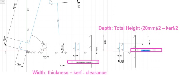
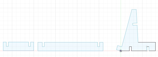
At the end, the profiles will look like the ones show in the following screenshot.
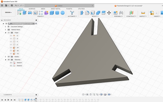
4. Extrusion and Copy: Choosing all the profiles, you could extrude by the parameter “thickness”. Then you copy the objects and prepare all the components on the workplane. After the extrusion, I put 1mm chamfer for each of the joints.
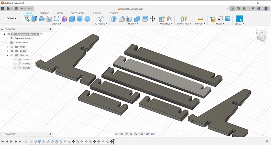
Data: F3D
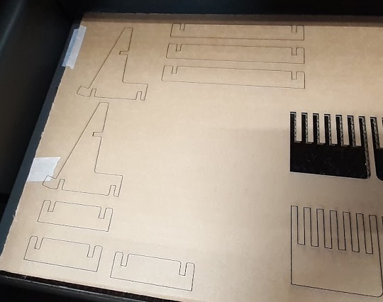
5. Laser-cutting and Assembly: Now you could proceed to laser-cutting. In my case, the first design was no good for horizontal placement because the stand felt backward due to the insufficient support on the back side. Therefore, I resized the stand frames by increasing their depth by 10mm. The second trial was a success for Android mobile phones. But it was still not good enough for iPhones which are smaller than Android phones.
For the parameter setting of the lasercutter, I applied the same parameter set I got in our Group Assignment for Week3
Power: 10 / Speed: 60 / PPI: 300 / Z-axis: 3.7
Kerf: 0.17mm
Clearance: 0.2mm
Design Data for This Exercise: F3D
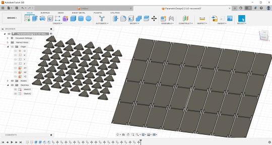
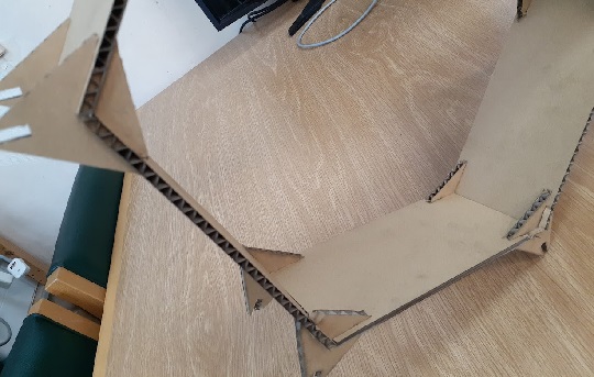
Parametric Construction Kit Design II
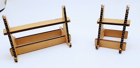
Based on the comments from the instructors at the Regional Review for Asia on Tuesday, February 13, I decided to try another parametric construction kit design. This time I tried to design the honeycomb shelves with cardboards. I have seen the similar design before, which was made out of wood boards and 3D-printed joints.
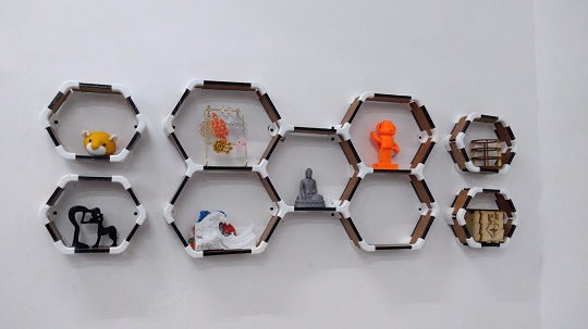
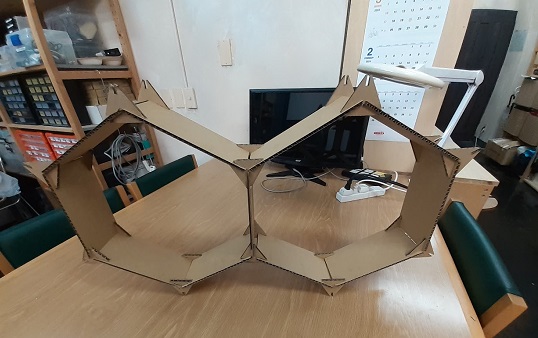
I designed with Fusion360. There were only two basic design components: the joint and the board. The board could be scalable. WIth 6 boards and 12 joints, you could form one honeycomb. Depending on your requirements, you can add more honeycombs. Also, you could apply two longer boards that could be layed horizontally to make horizontally wider cell.
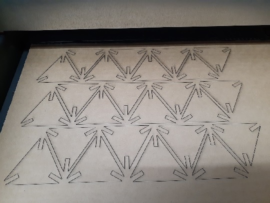
Here are some of the screenshots on my design process. I set my own paramters for kerf, clearance, and board thickness. Then I applied these parameters to the construction process. 1mm chamfer was added after I extruded the profiles.
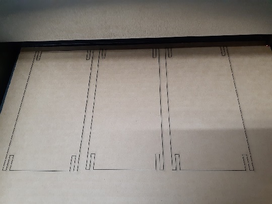
April 5, 2024: A few weeks later, I brought the above data files and cut out many pieces of those components. Although the size of the joints was fine enough to cut out many pieces required in one cardboard, I found that I could only cut out three pieces of the board components in one cardboard. Also, as soon as I made the first hexagon module, I found that one module was too big for a wall shelf. That made me feel that I should have reduced the length of the wall from 20mm to at least 15mm.
Design Data for This Exercise: SVG-Joint / SVG-Board / F3D
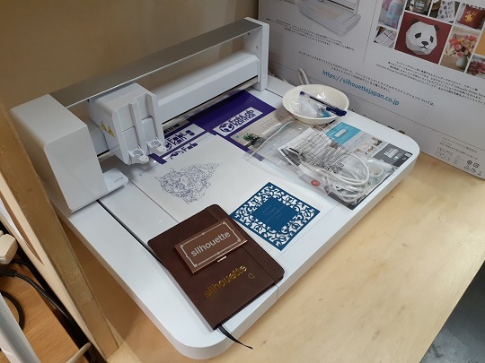
Vinyl-Cutting
The second individual assignment of the week was to cut something with the vinyl cutter available in the local lab. FabLab Kannai has been recently equipped with Silhouette CURIO2, flatbed cutting machine. It has a unique feature of the electrostatic bed which could hold thin materials in place rather than rollers or a sticky cutting mat. Also, it has a 20mm vertical clearance and we could lay even the thick material.
1. Preparation:
Before I proceeded this exercise, I did some preparations:
- Data: I used the same design I made in the previous week: “My Name” in terms of DXF file (vector data) for cutting and JPG file (raster data) for foil stamping. With this same design, I tried both sandblasting and foil stamping. DXF / JPG

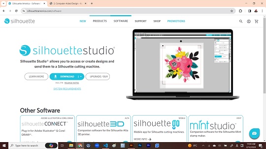
- Software: Next I visited the Curio 2 webpage and downloaded/installed the design software “Silhouette Studio” in my laptop.
- Software and Machine Setup: The overview of the software setting and machine setting are available in the Fab Academy @FabLab Kannai webpage.
2. Project I: Vinyl-Cut and Sandblasting
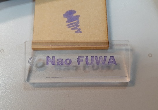
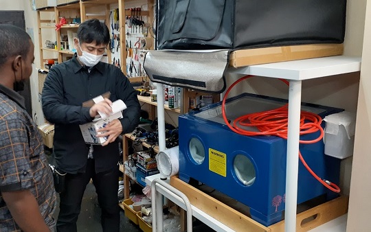
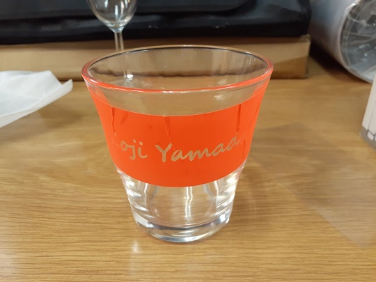
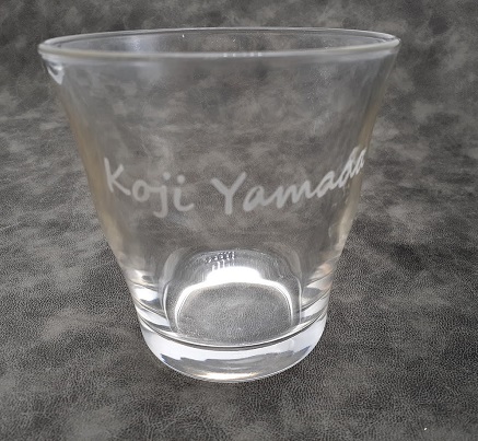
The first project was to make the seal on the glass for my name to be sandblacted on the surface of the glass. FabLab Kannai is equipped with a sandblaster with a sand-collector.
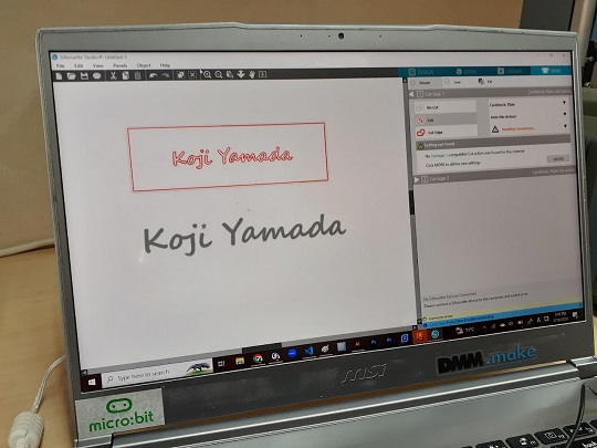
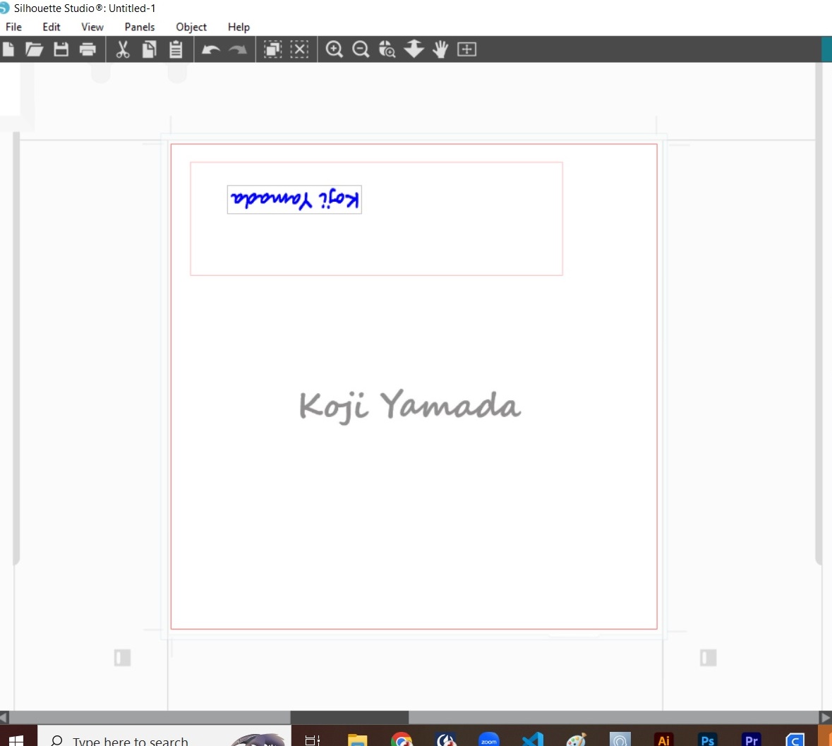
Once I started the program, I imported the DXF file. But then I have found that we could only get unclear outline. After consulting with our instructor, I decided to import the JPG file and trace the outline on the workspace of the Silhouette Studio. It’s better to draw another rectangle covering the texts because I wanted to have the insides of the text shape sandblasted. This rectangle could work as a masking tape to protect the glass surface from sands.
-
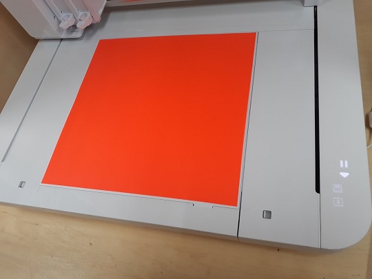
Electrostatic Activation: Then I turned on the cutting machine and placed the material on the cutting board. Once I pressed the electrostatic activation button on the right front control panel. As soon as it was turned on, the material was sticked to the cutting table.
-
Install the Cutting Blade Attachment: Next install the Auto Blade attachment on the tool carriage 1 on the left.
-
Setting Parameters: Back to my laptop, click the “Send” tab on the Silhouette Studio. Then my laptop connected to Curio 2 and set all the parameters, including: cutting conditions (materials to cut), actions requred, type of attachment (Auto Blade in my case), and then blade depth, force and speed. You have to find the best combination of the parameters through trials and errors.
-
Cut: Now it’s ready for cutting. Please see how it moves by watching the following video:
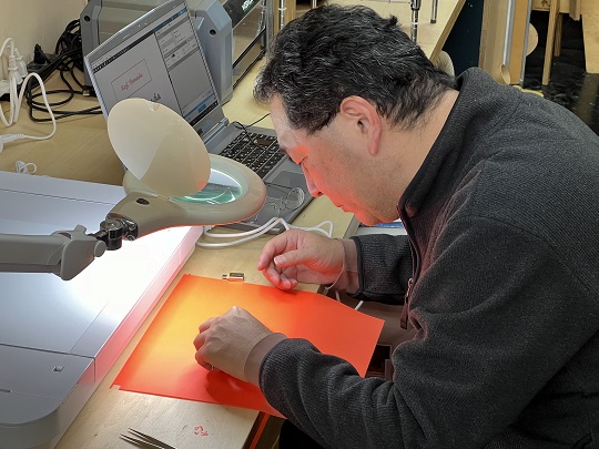
- Post-Cut Treatment: Once the cutting operation was completed, remove the cutting sheet from the bed. Using tweezers, remove all the cut-outs carefully. It is hard to see where to peel off the cut-outs. Magnifier may be helpful. In my case, old age and hereditary astigma made it so difficult to peel them off quick and accurately. After removing all the small pieces, I pasted the base rectangle around the glass.
- Wrapping the Object with Masking Tape: If you want to sandblast only the letters, you have to protect other par of the glass with a masking tape so that it would not be affected. If you want to sandblast the glass around the cut-out, you don’t have to wrap the glass around. However, in either case, you have to cover the inside wall by covering the whole lip of the glass with a masking tape.
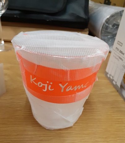
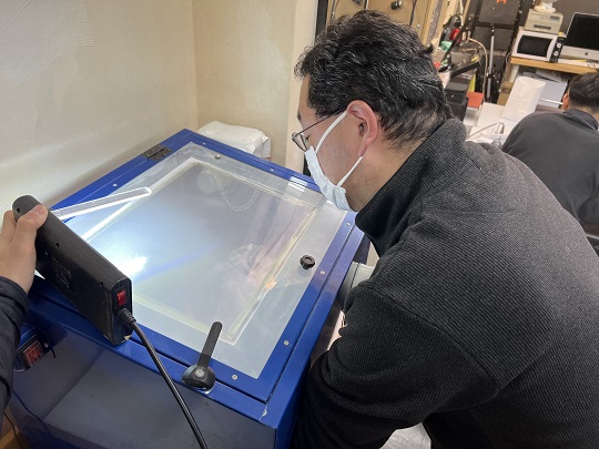
- Blast!!: Wear the face mask so that you could prevent yourself from breathing powder sands in. Be sure to lock the top cover so that the powder sand dust could not be discharged out into the whole work room. Also, be sure to turn on the vacuum compressor. After those checks, you could start the blast with a pressure gun inside the . It doesn’t take much time. You could check the progress through the cover window. After the blast, take the glass out of the blaster, peel off all the masking tapes, wash it and it’s done.
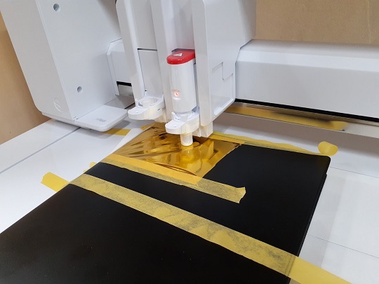
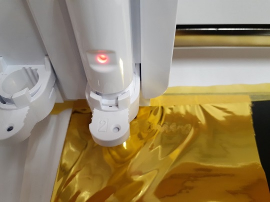
3. Project II: Gold Foil Stamping
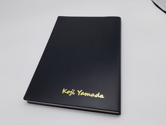
The second project was to press the gold foil stamp on the polyvinyl chloride (PVC) foamed sheet of my diary, utilizing the Heat Pen, one of the key features of Curio 2.
- Data and Placement: I used the same design “My Name”. However, this time, in addition to the outline, I needed infill. Therefore, I imported the JPG file of the same design and did the outline trace with the Silhouette Studio. In order to set the target area for stamping, I used the same rectanglar outline I made in my first project. Since I wanted to stamp my name near the bottom right corner of the back side of my diary, I rotated the diary and placed the bottom right corner to the top left corner of the Curio 2 table.
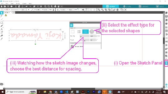
- Adjustment on the Sketch Panel: Before proceeding to the “Send” tab, you have to stay at the “Design” tab for a while and open the Sketch Panel to finetune the expected outcome by manipulating the parameters including the sketch pattern, spacing and angle.
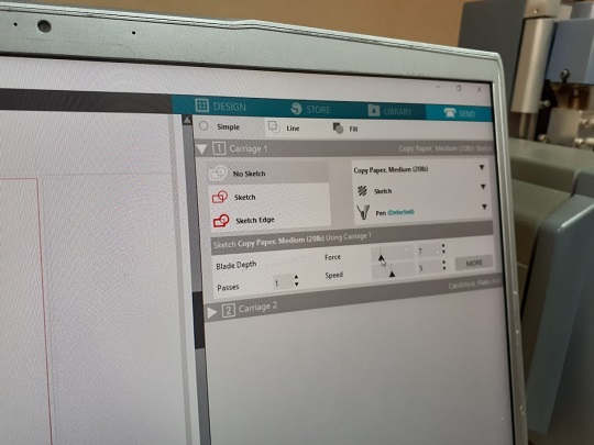
- Carriage 1 Setting: First, mount the Pen Holder adapter on to the Carriage 1. For detailed instruction to prepare the adapter, please see instruction guide of FabLab Kannai. Then go to the Silhouette Studio and proceed to “Send” tab, then to “Carriage 1” tab. Select the rectangle on the sketch palette and then with the control panel for Carriage 1 on the right, choose the parameters including: cutting conditions (“Copy Paper” in this case), actions requred, type of attachment (“Pen” in this case), as well as Pen Force and Pen Speed.
- Draw Outline on a Paper: Place the copy paper on the cutting table so that the top left corner of the paper is touching the top left corner of the cutting table. Then activate the electrostatic function. Now ready for drawing.
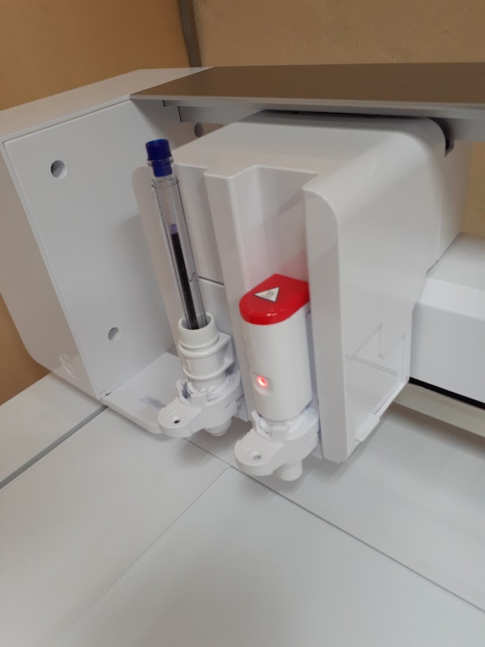
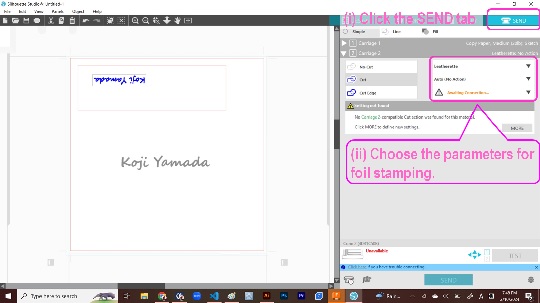
- Carriage 2 Setting: First, mount the Heat Pen attachment on to the Carriage 2. Then go to the Silhouette Studio and proceed to “Carriage 2” tab. Select the letters to be stamped on the palette and then with the control panel for Carriage 2 on the right, choose the parameters including: cutting conditions (“Leatherette,” in this case), action required, type of attachement (“Heat Pen” in this case) as well as Pen Force and Speed.
- Stamping!!: Place the diary to be stamped. You can place materials which have the thikness of up to 20mm. My diary was okay. Since the diary is not good for electrostatic adhesion, I had to fix the position with masking tapes. Then cut the foil material sheet to a small piece which will cover the rectanglar area outlined above. Place the foil at the target area of the diary and fix the position with masking tapes as well. It may take a few minutes for the cutting machine to complete the task.
Please watch the following video to see how the machine moves.
Please take a look at my hero photo.
Difficulties Faced
-
In the case of the local session at FabLab Kannai, we only have one full Saturday to work for our hands-on experience together with the other students. It takes almost two hours to go to our local lab and I have other jobs on weekdays. That makes it difficult for me to spend much time in familiarizing myself to the laser-cutter and the cutting machine.
-
Time Management: In the local session on Saturday, February 10, we spent the whole morning session for group assignment and had only half day in the afternoon for individual assignments. That means we had to be so efficient to come up with an idea for designing a parametric construction kit of our own. If we spent too much time for ideation, we might end up with limited time for machine operations. Since we started with laser-cutting, there was a high risk of missing an opportunity to operate the vinyl-cutting.
-
10MB Quota for Git Push and Recovery After Push Failure: Although I had been aware of the quota of 10MB per git push, I exceeded it when I tried to push two videos in one push. As a result, my push was rejected by Gitlab. In the past global sessions, we had been told to push files separately so that one push could remain in the 10MB quota. It was the first time for me to recover after rejected large files commit. With the guidance of the two instructors, I could somehow complete the recovery. For the benefit of myself in the future, I hereby document the steps I have taken:
(i) Return to the Status Before the Commit: By placing the following command, I cancelled the commit and returned to the status before commit. After the reset, checked the status by “git status”:
git reset --soft HEAD^
(ii) Cancell Git Add for the Large File: By placing the following command, I cancelled the git add for the file which probably caused exceeding the git push limit. After the cancellation, checked the status by “git status” and committed and pushed with the files less than 10MB:
git reset docs/Weekly Assignments/images/file_name.mp4
Probably the main reason for exceeding the git push quota is mp4 files. When this failure occurred, I was trying to push two mp4 files after the video compression. I thought that the video compression with ffmpeg would always help us avoid the quota violation. Then I thought that if I reduced the number of mp4 files to one to commit at one push, this problem could be solved.
However, I faced the same error message of quota violation. Then I checked the file volume and found that in some cases, even after encoding, the video data file might still been exceeding 10MB. We should always check the file volume.
The last resort was to re-edit the video data file and cut it shorter. If it’s from 30 seconds to 50 seconds, the file would not exceed the 10MB threshold.
(iii) Add the Excluded File Again and Commit: After checking the file volume after the re-editing and compression, I added that particular file only and then proceeded to commit by placing the following two commands. After completing each of the steps, we had better check the status by “git status”:
git add docs/Weekly Assignments/images/file_name.mp4

git commit -m "add file_name only"(example)

git push