12. Molding and Casting
Weekly Digest (Thu. April 18 to Wed. April 24)
| Date | Time | Place | Activities |
|---|---|---|---|
| Thu. April 18 | 09:00-12:00 | Home | (Final Project) Literacy Survey on Raspberry Pi PICO W |
| 14:00-18:30 | FabLab Kannai | Unfinished activities for Week5 and 11 / Consultation with Instructor | |
| Fri. April 19 | 09:00-12:00 | Home | Documentation for Week5 / Unfinished activities for Week11 |
| 13:00-19:00 | Home | Unfinished activities for Week11 / (Final Project) Reverse Engineering of the Security Alarm | |
| 21:30-24:00 | Home | (Final Project) Documentation | |
| Sat. April 20 | 10:00-21:00 | FabLab Kannai | Local Session for Week12 |
| Sun. April 21 | 08:00-10:30 | Home | Documentation on Week12 Group Assignment |
| 18:00-19:00 20:00-01:00 | Home (Gifu) | Documentation on Week12 Individual Assignment | |
| Mon. April 22 | 10:00-13:00 18:00-21:00 | Home (Gifu) | Documentation on Week12 Individual Assignment (cont’d) |
| 22:00-23:30 | Home (Gifu) | Documentation on Week12 Group Assignment (cont’d) | |
| Tue. April 23 | 11:00-12:00 17:00-18:00 | Home (Gifu) | Documentation on Week12 Group Assignment (cont’d) |
| Wed. April 24 | 14:00-18:00 | Home (Tokyo) | Unfinished activity for Week11 |
| 21:00-22:00 | Home | (Final Project) Buzzer Test |
Individual Assignments Overview
Here is the list of individual assignments given by the instructors. As for the Group Assignment, please see the Group Assignment page on the FabLab Kannai website:
  Design a mold around the process you’ll be using,
  Produce it with a smooth surface finish,
  and use it to cast parts
  [Extra Credit] Use more then two mold parts
Although we were advised in the last global session that we should work on the design for our final projects, I would like to make it clear that my design this week has nothing to do with my final project.
1. Initial Ideas for Molding and Casting
In order to efficiently utilize the limited time for the hands-on session at our local lab, I prepared a few different design for molding and casting.
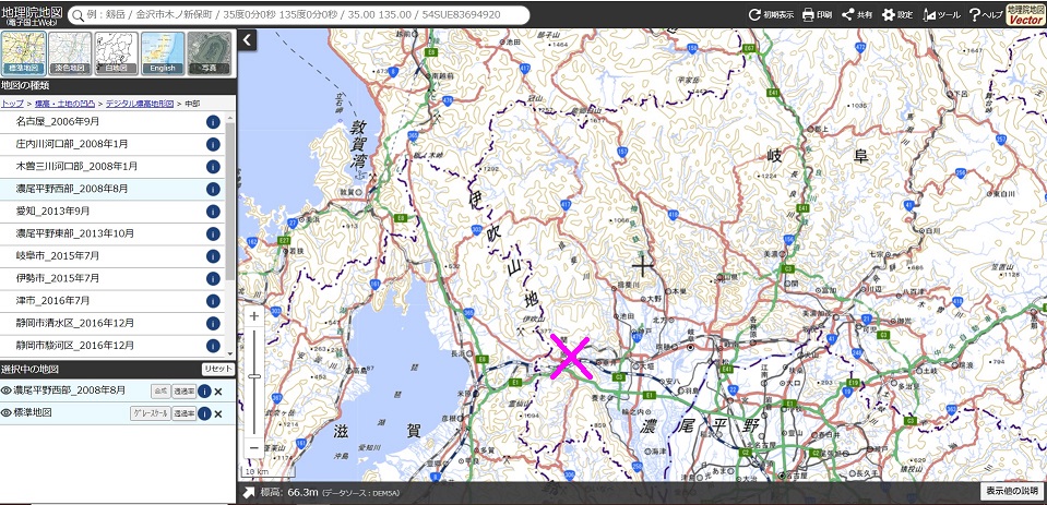
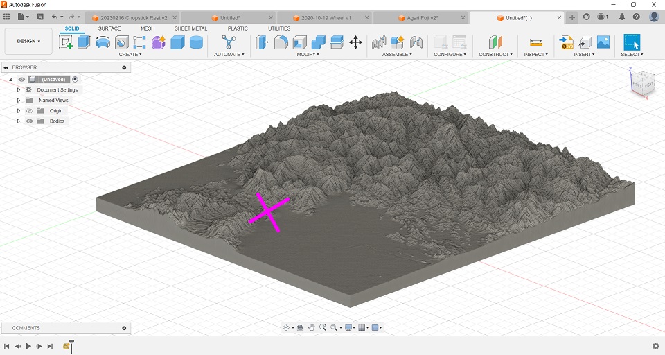
- Landscape of Japan: Geospatial Information Authority of Japan, GSI, makes the digital topographic map data of Japan in various resolutions and we can take easy access to this data infrastructure. Therefore, I first thought of making the 3D landscape model of my home village area near the Isthmus of Sakigahara, which became a civil war battle ground three times in history. Before I proceeded to downloading the 3D data in terms of STL file from the GSI website, I magnified the height by 300 percent for the Sekigahara landscape because I had a past experience in 3D-printing the landscape of the Phuentsholing area in Bhutan and found that the landscape looked flatter than expected if it’s 1 x 1 x 1. For attracting the readers, I also downloaded the 3D data of the Mt. Fuji area by the magnification of 1 x 1 x 2. One disadbantage of this idea is that it takes many hours to mill the wax. When I 3D-printed the landscape of Phuentsholing by 15cm x 10cm, it took 11 hours. For the sake of time management, I decided not to do this for my individual assignment of the week.
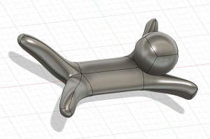
- Chopsticks Stand: A few months ago, I did a few exercises of skulpt modeling and designed a chopsticks stand on which we place chopsticks. It had a curved surface and looked good for this week’s assignment. Also, it’s small. However, as I took a close look at the shape, I started wondering how I could make a silicone mold. Safety was another concern if I use it in my daily life. After such considerations, I finally decided not to try this. (I have found the way out later, and will try it after the Fab Academy.)
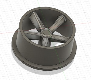
- Miniature Car Wheel: This is another design I made a few months ago for my self practice. It’s small, too. However, again I wondered how I could make a two-piece silicone mold. It could be a nice example for extra credit (more than two mold parts). But I wanted to start with a simple two-piece model.
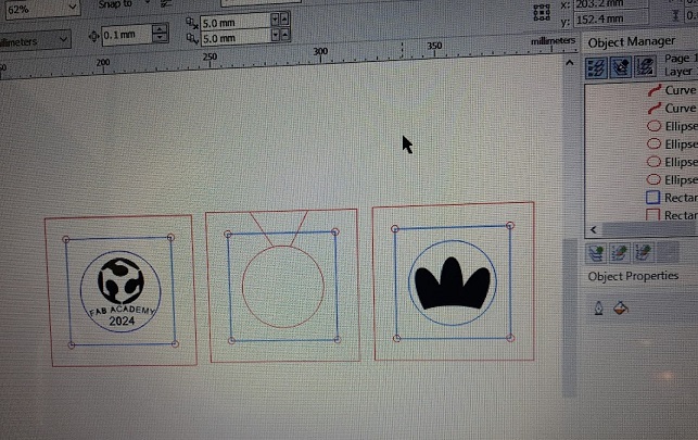
2. Final Design Idea for Individual Assignment
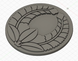
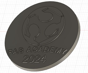
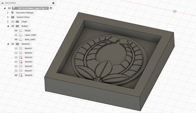
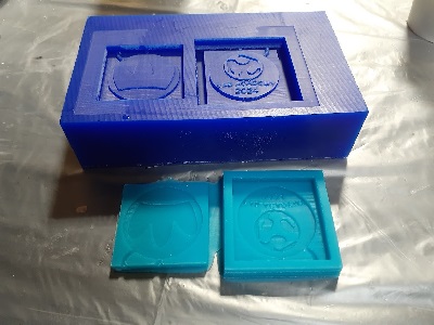
None of my above ideas was adopted, and I had to spend time in designing from scratch during the local session. That led me to take an easy option: making a double-sided medal, with the Japanese clan symbol, kamon, of the Yamada family on one side and the FabLab logo with a few texts on the other.

One advantage of this design is that we could try both wax molding and lasercut MDF molding and compare the two approaches.
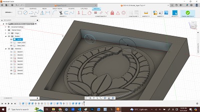
I prepared the original design on Fusion360: F3D Data
3. Wax Molding
3-1. Data Preparation
Here is the data preparation process for wax molding with Fusion360.
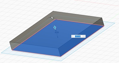
[Step 1] Set the offset plane to cut the target shape. (In my case, I moved the shape down along the Z-axis by 2mm and used the original XY plane as the plane for new sketch.)
[Step 2] Switch to the “Creat Sketch” mode on the offset plain (in my case, XY plain) and draw a rectangle which wraps the target shape.
[Step 3] Draw another rectangle outside the first one with the offset distance of 4-5mm. Then finish the sketch mode.
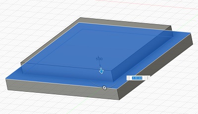
[Step 4] Click the inner rectangle as a sketch profile and extrude it by 5-6mm. Be sure to select “New Body” in the “Edit Feature” dialogue.
[Step 5] Click the two rectangles as profile and extrude them toward the other direction than Step 4 above by 5-6mm. Again, it must be a “New Body” in the “Edit Feature” dialogue.
[Step 6] First hide the body in the browser that you made in Step 4. Click the gap beween the outer and inner rectangle as profile and extrude it upward by 5-6mm. This time, be sure to slect “Join” in Orientation in the “Edit Feature” dialogue.
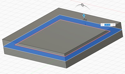
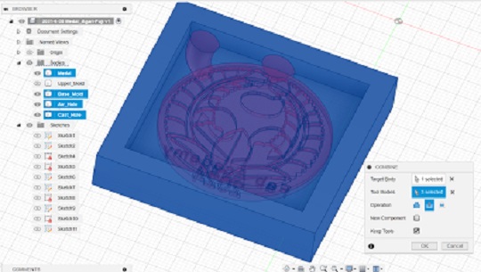
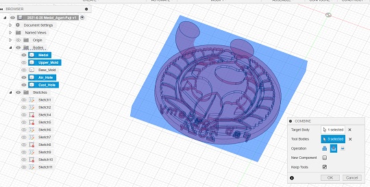
At this point of time, there are three bodies in the browser. Only the body numbers are assigned to these bodies. It’s better rename the bodies by, say, “Medal”, “Upper_Mold” and “Base_Mold.” By switching between “Hide” and “Show” for each of the bodies in the browser, you can see how they look.
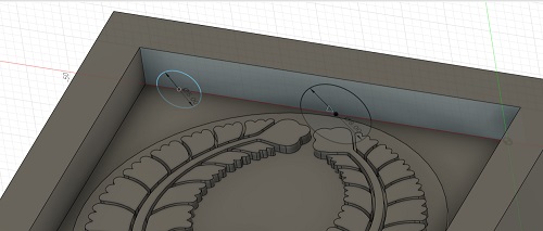
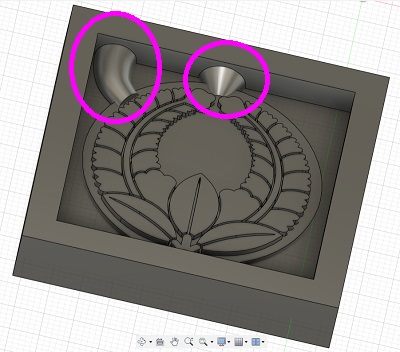
[Step 7] Hide the Upper_Mold and make two holes as “New Body”. One hole is for pouring the liquid material into the mold, and the other is for air to pass through. The hole placed along the center line of the mold is for ventilation while the one coming into the mold from top left side of the mold is for casting. The entrance of both holes should be as big as possible. This is very important for the hole for pouring the liquid material as quickly as possible before it becomes solid.
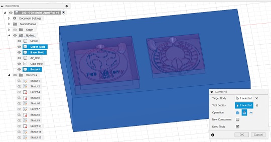
[Step 8] Click the “Combine” icon. Select the Base_Mold shape as “Target Body” and the model shape and two holes as “Tool Body” in the “Edit Feature” dialogue. Operation is “Cut” and you check the “Keep Tools” box. This means that even after the cut, these shapes will remain as body.
[Step 9] Do the same process for the Upper_Mold. First, hide the Base_Mold in the browser and show the Upper_Mold instead. Then click the “Combine” icon and select the Upper_Mold shape as “Target Body”. Then hide the Upper_Mold in the browser and select the same three bodies as Step 8 above as “Tool Body”. Select “Cut” and check the “Keep Tools” box.
At this point of time, the two positive molds are made.
[Step 10] Measure the size of the Matt Wax and design the same shape on the Fusion360 workplain.
[Step 11] Move both the Upper_Mold and Base_Mold to the top surface of the Matt Wax, rotate the Base_Mold by 180 degrees and place them in such a way that the bottoms of the molds could coincide with the top surface of the wax.
[Step 12] Click the “Combine” icon. Select the Matt Was as “Target Body” and the Upper_Mold and the Base_Mold as “Tool Body” in the “Edit Feature” dialogue. Operation is “Cut” and you check the “Keep Tools” box.
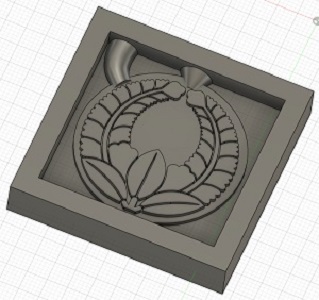
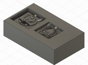
Now the Matt Wax looks like the following image. However, here you need to consider how deep the endmill could reach down when it mills the Base_Mold.
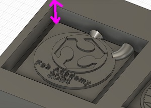
Perhaps you will use the 1/16 endmill for final cut and the top of the endmill is just 6.125mm. It definitely cannot reach straight down deep into the bottom of the Base_Mold. In this case, we had better give the outer wall a taper angle so that the mill could go down on the slope step by step.
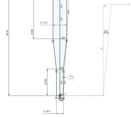
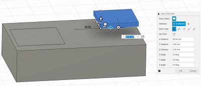
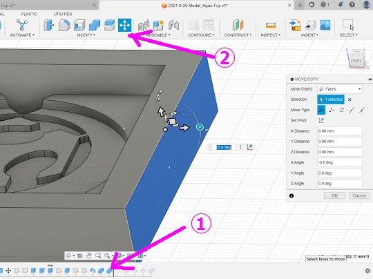
[Step 13] Move back on the history bar to the point before you start designing the Matt Wax. Hide the Upper_Mold body so that you could only see the Base_Mold. Then click the “Move” icon, select “Faces” in the “Move Object” menu in the “MOVE/COPY” dialogue and select one of the outer walls of the Mold. Then rotate the wheel so that we could give 5 degrees of taper angle to the face. You do this process for all the four walls.
[Step 14] Download the STL file data of the Wax. F3D / STL
3-2. Prepare the Toolpaths for Milling
3-2-1. Tools
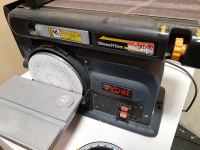
At FabLab Kannai, we were supposed to use the following tools besides the machinable wax, which I have already mentioned above.
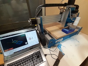
  Machine: Genmitsu PROVerXL (work area: 400mm × 300mm × 110mm)
  Endmil
  (Rough Cut) 0.1250” DIA 4FL SE LONG AlTiN 1/8
              Tool_dia: 1/8” =3.175mm
              OverAll Length: 2-1/4”(2.25”) =57.15mm
  (Finish Cut) 0.0625” DIA 2FL SE AlTiN 1/16
              Tool_dia: 1/16” =1.5875mm
              OverAll Length: 1-1/2”(1.5”) =38.1mm
Although we had the 1/16 endmill for finish cut, we got the 1/32 endmill ready, too, for more precise milling.
3-2-2. Making Toolpaths
Using the Mods, we prepared the two toolpaths: one for rough cut and another for finish cut.
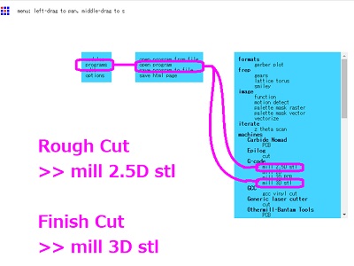
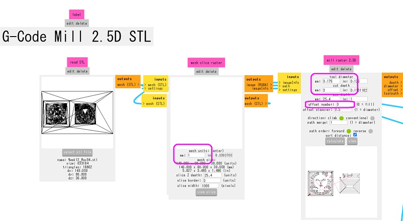
Rough Cut: Import the STL file of the Matt Wax. Mods automatically reads the dimentions of the wax. Otherwise, we have to change the mesh unit to 1mm. Then we proceed to the “Mill Raster 2.5D” dialogue and input the tool diameter and cut depth as per the specs of the endmill. Also, we changed the “Offset Stepover” parameter to zero. Once we click “Calcurate”, we could download the gcode data on the toolpath.
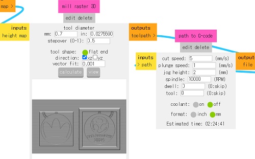
Finish Cut: Open the mods once again and import the same STL file of the Matt Wax. First we have to change the mesh unit to 1mm. Then we proceed to the “Mill Raster 3D” dialogue and input the tool diameter as per our requirement. According to my first plan, I was supposed to go with the 1/16 endmill (Tool_Dia: 1.5875mm). However, once I calcurated the toolpath, I found that I could not get a clear cut for the family clan symbol. Therefore, I tried with the 1/32 endmill (Tool_Dia: 0.79375mm). We have to see whether we should leave both the XZ and YZ directions. If we tick both direction boxes, it will take extra time for milling. Once we set all the parameters in the “Mill Raster 3D” dialogue, we had better proceed to the “Path to G-code” dialogue to change the parameters for cutting. Once all the parameters are set, we go back to the “Mill Raster 3D” dialogue and click “Calcurate.” The gcode data will automatically be downloaded.
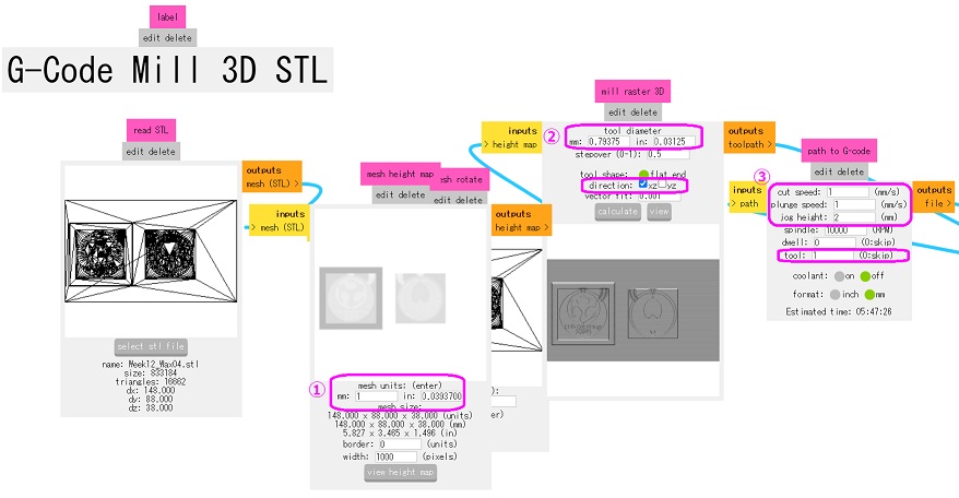
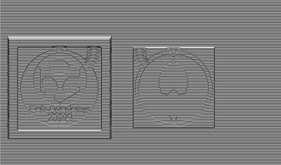
Now you could easily see what’s wrong with my design. Even with the 1/32 endmill, I am not able to get a clear cut.
3-3. Milling
Despite the above-mentioned risk, I decided to proceed to the milling process. Here I found a couple of mistakes. Although I once thought of trying again on the date of the local session, I decided not to because I already ran out of time.
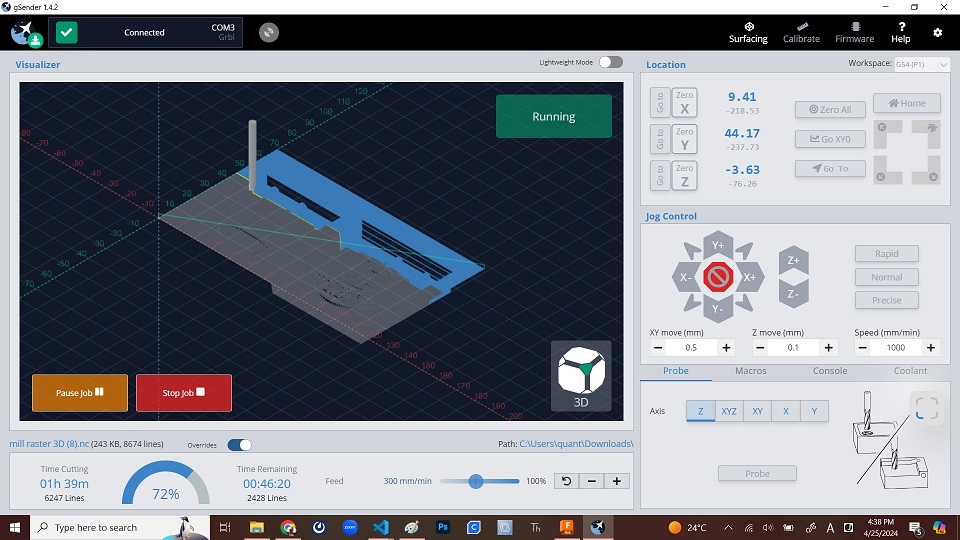
Problem 1: Setting the Origin in a Wrong Place It seemed that I set the XY origin too deep inside the Matt Wax and that affected the milling result of the second mold. It turned out when the milling machine proceeded to the rough cut of the second mold. I continued the rough cut because this mistake didn’t affect the main body of the Base_Mold. I learned the lesson that the XY origin should be set more carefully.
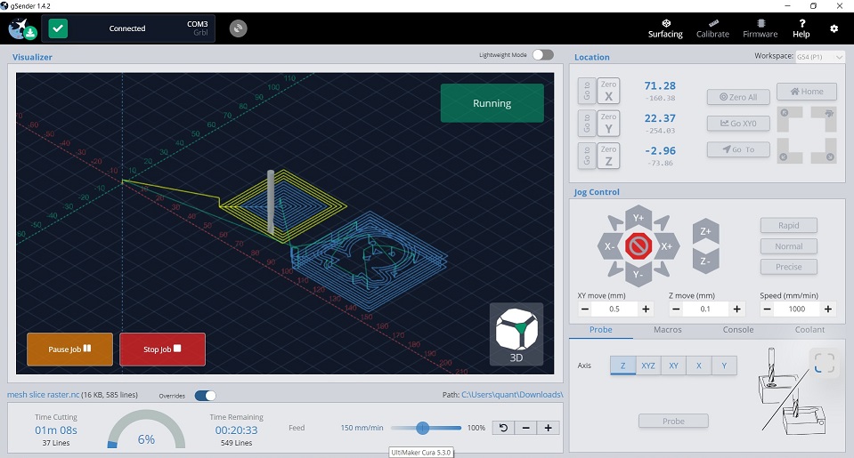
Problem 2: Time for Finish Cut Another problem I faced was about the time required for the finish cut. Consulting with the Instructor, I decided to move on to the finish cut based on the rough cut which ended up with a missing wall of the Base_Mold. However, once I did all the settings and got ready for finish cut, the g-sender panel indicated that it would take more than 21 hours. Since I changed endmills from 1/16 to 1/32 and that might cause doubling of the time for milling. Secondly, when I worked for setting the parameters, leaving the directions of the milling both XZ and YZ checked. That might also take double time for finish cut.
There were a few measures I could think of in order to save the time for finish cut.
-
Wax Size on Fusion360: Instead of sketching and extruding with the exact dimensions, we could reduce the size of the wax on which we place our positive molds. STL
-
Cut Speed on Mods: Perhaps the most critical parameter to save time. The Mods’ default is 2mm/s. If we double the speed, we could save the time for finish cut by 50 percent.
-
Mill Raster 3D Direction on Mods: The default setting is both XZ and YZ directions. If we select only one of them, the spindle would move only along either left and right (XZ) or forward and backward (YZ), we could save time by another 50 percent.
Problem 3: Broken Endmills: I broke three endmills before I finally came up with the best formula for my design:
  Cut Speed: 5mm/s
  Plunge Speed: 1mm/s
  Jog height: 2mm/s
  Spindle: 10,000rpm
But even so, the control panel showed that it woud take more than 2.5 hours.
Please note that the best formula might not always be the same.
Based on the above formula, I could somehow finished milling the wax.
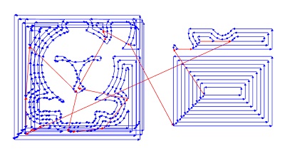
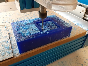 Rough Cut
 After Finish Cut
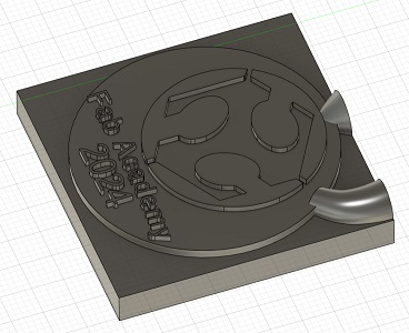
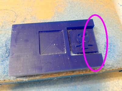
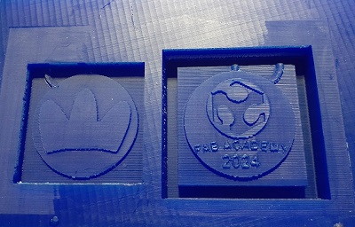
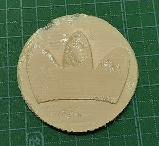
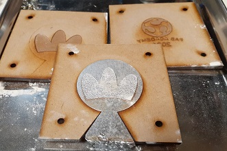
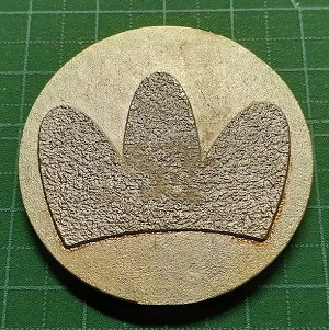
After the finish cut, I found that there were still two problems with my design:
-
Texts: Even with the 0.7mm endmill, texts were not well embossed. This was already expected when I created a toolpath for final cut. But I compromized.
-
Horizontal Milling Traces: In order to save time for final cut, I decided not to go both XZ and YZ directions. As the result of my selection of XZ direction, the end result of the final cut shows there are horizontal traces of the endmill movement. If I had left both directions, it would have taken double time even though we could get a better result. It was expected that this compromize could affect the result of the text cast.
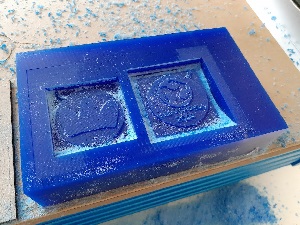
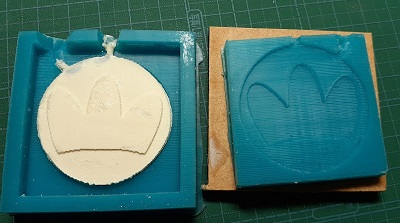
3-4. Casting
3-4-1. Negative Mold with Liquid Rubber
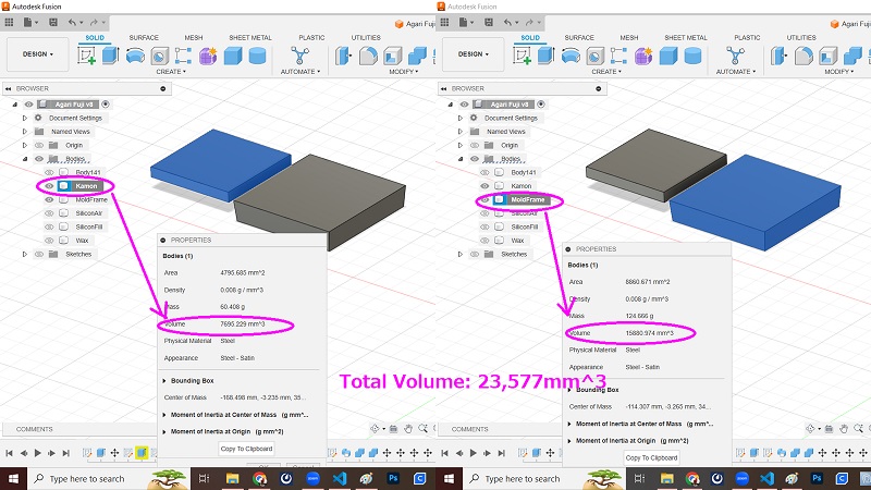
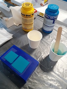
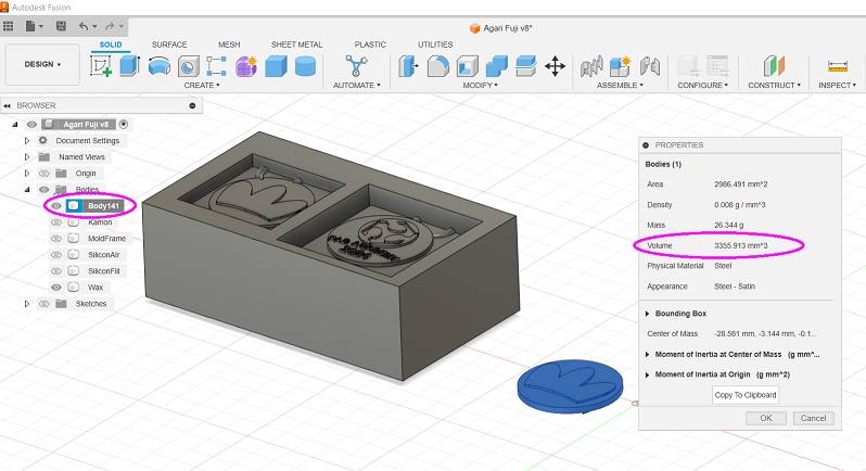
With this compromized positive wax mold, I made the negative mold with silicone rubber, Mold-Star 16. First, I calcurated the total liquid silicone requirement on Fusion360 by right-clicking the respective bodies on the browser and selecting “Property”. For the negative, the total volume requirement was approximately 24cc.
According to the Technical Data available on the Mold-Star 16 website, the volume-gravity conversion rate is 1.18g/cc. Therefore, the total required volume of the silicone mold is calcurated as 28.32g (24 x 1.18). Since the same Technical Data show the mix rate of the two liquid by weight is 1A:1B, I could calcurate that we need approximately 15g for each liquid.
After pouring the two liquid, I maddled the liquids well and then poured it into the wax mold. According the the Technical Data, the Pot Life is 6 min and Cure Time is 30 min. Maddling the two liquids quickly, we had to pour it and wait more than 30 minutes.
 Wait 30 min.
 Take them out by digging by fingers
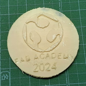
3-4-2. Casting Liquid Plastic
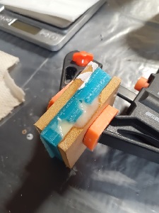
Now that the two negative molds were ready, I put them together and held them tight with a clamp so that I could use both hands for casting liquid plastic.
For casting, I decided to use Smooth-Cast 320. Similarly to the case of negative mold, I started with the calcuration of the total liquid volume requirement by Fusion360, and expected that it would be 3,356mm^3 (=3.4cm^3).
According to the Technical Data available on the Smooth-Cast 320 website, the volume-gravity conversion rate is 1.05g/cc. Therefore, the total required volume of the liquid plastic is calcurated as 3.6g (3.4 x 1.06). Since the same Technical Data show the mix rate of the two liquid by weight is 100A:90B, I could extimate that the Bottle A could be 1.9g while the Bottle B is 1.7g.
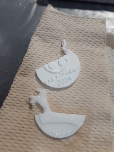
Again the Technical Data shows that the Pot Life would be just 3 min while the Cure Time would be 10 min. So, I mixed the two liquides more quickly and poured it into the casting hole until I saw overflooding from the ventilation hole. Here I faced the problem of small casting hole. If it’s too small, I could not finish casting liquid plastic before it became solid and started plugging the hole. After making it bigger and by using a flextible bottle and a tube, I could get the complete plastic medal.
 Many failures.
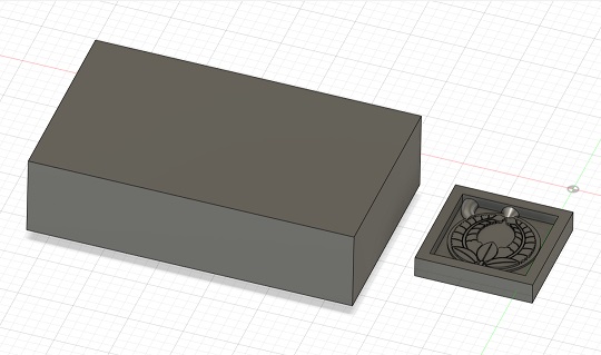
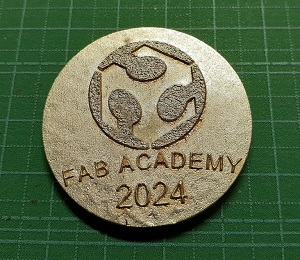
3-5. Hero Photo
4. Making Mold by Lasercutting
While I was waiting for my turn to operate the CNC router, I tried to make another mold with the MDF board by operating the lasercutter.
4-1. Data Preparation
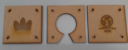
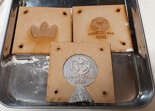
[Step 1] I did the data praparation on Fusion360. With the Shaper Utilities tool, I made three SVG files: Family Clan Symbol / FabLab Logo and a Few Texts / Outline of the Medal.
Please note that since I found that the family clan symbol, Agari Fuji, was too fine and I couldn’t get a clear toolpath for milling. After a few thoughts, I decided to replace the clan symbol with another logo I designed a few weeks ago.

[Step 2] Then I brought these data to the CorelDRAW paired to the lasercutter. After importing the three files to the workplain, first I drew rectangles with the same size that wrap the target bodies. These are the reference shapes to place a screw hall with a diameter of 3.2mm at each of the corners and the outline should be blue-colored. These holes were for cutting, and therefore I colored them red hairline. Then I drew the offset rectangles outside all the three reference rectangles and colored them red hairline for cutting.
Here is the summary of the actions taken for each of the three boards, including the color combination.
| SN | Item | Actions Taken |
|---|---|---|
| 1 | Yamada Product Logo | Logo (black), circle around the logo (blue), inner rectangle (blue), 4 screw holes (red hairline) |
| 2 | FabLab Logo & Texts | Logo and texts (black), circle around the logo (blue), inner rectanble (blue), 4 screw holes (red hairline) |
| 3 | Medal | Medal shape (red hairline), inner rectangle (blue), 4 screw holes (red hairline), and 2 straight lines for cutting the route for casting and ventilation (red hairline) |
4-2. Lasercutting
The following snapshot shows the result of the lasercutting.
4-3. Mold Assembly
Here is the comprehensive view of the items prepared for the casting and molding with lasercut MDF boards. They include: Stainless tray (1), volts and nuts (4 pairs), baby powder (1), brush (1), clamp (1), screw driver and wrench (1 each). Besides the above items included in the photo, I prepared: ladle (1), ladle stand (1), burner (1).
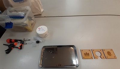
Before assembling, I powdered the surface of the mold. Baby powder is made from tarc and good for protecting the mold from the melted metal.
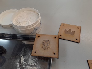
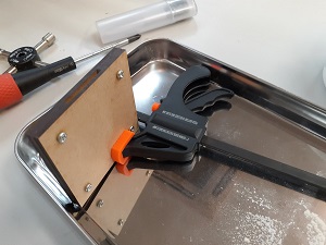
After wiping off the baby powder by a brush, I assembled three boards and tie them with bolts and nuts. The reason for using the clamp is to hold the mold in a position good for me to pour melt Bismuth-based alloy ingot without holding the mold by hand.
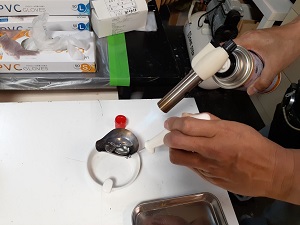
4-4. Casting Alloy
As explained in the documentation on our Group Assignment, Bismuth-based alloy ingot has a low melting point of 138 degrees Celsius. It’s low and will not damage the MDF mold. (I could have tried tin as well.)
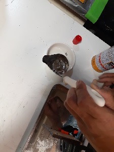
After aiming the burner at the alloy ingot, it started melting in the ladle. First, we had better remove alloy oxide forming on the surface of the melted alloy. When it’s heated enough, then I poured it into the MDF mold. It flew quickly.
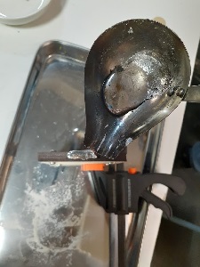
4-5. Cast Off
After waiting for 10-15 minutes, I casted off the MDF boards and took the medal out. For the metal filled in the casting/ventilation hole could be nipped off easily by nipper. Then I ground the round surface by belt sander for finishing.
4-6. Hero Photo
5. Findings and a Few Remarks
Here is the recap of what I have done so far this week:
-
Although I was informed in advance that I could get a better molding and casting resut with my original design of Agari Fuji (ascending wisteria), clan symbol of the Yamada family, I decided to do it replacing the original design with my logo.
-
In the meantime, I couldn’t finish the silicone molding with the Agari Fuji design due to the time constraints. But since I couldn’t get a clear toolpath for this design, I am expecting that I would not get a good molding and casting result with the original Agari Fuji design. Also, while I was waiting for my turn, I observed the other student’s struggles in pouring liquid plastic into each of the very tight corners of the mold, I thought that it would be more difficult to get a better molding and casting result with my medal, even after replacing the original Agari Fuji design with more simple Yamada product logo.
-
If we had used an SLA 3D printer, not FFD/FDM 3D printer, we might have been able to make a better mold.
Finally, I would like to post two YouTube videos.
I made the first one a few months ago at FabLab CST in Bhutan. In order to attract local children, I had planned an accessory-making workshop and made or brought molds to cast UV resin. Although it was fun enoguh, I also learned that 3D-printed molds might have problems on the smoothness of the surface. Silicone rubber and liqid plastic materials were not always available in the small landlocked developing countries.
The second one was also produced at FabLab CST in Bhutan when it hosted a Fab Bhutan Challenge “Aluminum Waste, Gracefully Braced” before the FAB23 conference in July 2023. Here in this rapid prototyping challenge, we worked on molding and casting of aluminum waste for making joints for the assistive tool for the local school student with disability. We collected the beer cans trashed out along the national highway and the melt them in the 2L electric furnace. On the other hand, we made a sand mold.
In conclusion, there are many more materials and many more approaches to molding and casting. We had better be aware that what we have learned in the Fab Academy session was only a tip of the iceberg.